&
Assembly Instructions
OWNER’S MANUAL
V. GCLP100-20210415
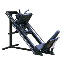
GCLP100
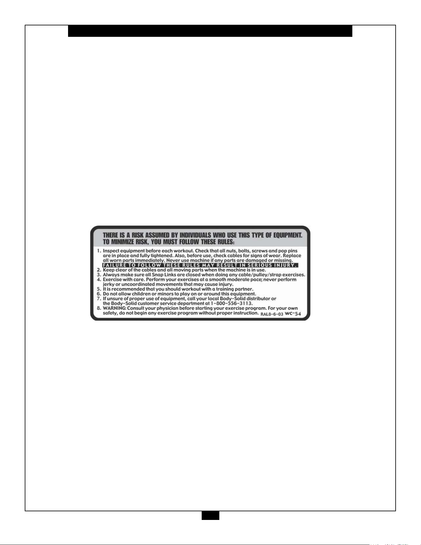
Warning, Safety & Maintenance
2
Be sure that all users carefully read and understand all
warning, safety and maintenance labels on the machine
before each use. Failure to do so may result in death or
serious injury.
It is imperative that you retain this Owner’s Manual and be
sure all warning labels are legible and intact. Replacement
Owner’s Manuals and warning labels are available from your
local Body-Solid dealer.
If you have any questions about the operation, set up or
maintenance of this machine please call our customer service
department at 1 (800) 556-3113.

Table of Contents
3
• SAFETY INSTRUCTIONS.............................. PAGE 4
• PREPARATION............................................... PAGE 5
• PART / HARDWARE LIST............................... PAGE 6
• HARDWARE ILLUSTRATION......................... PAGE 8
• ASSEMBLY INSTRUCTIONS.........................PAGE 12
• EXPLODED VIEW.......................................... PAGE 23
• CONTACT PAGE............................................ PAGE 24

Important Safety Instructions
4
Beforebeginninganytnessprogram,youshouldobtainacompletephysicalexaminationfromyourphysician.
Il est conseille de subir un examen medical complet avant d’entreprendre tout programme d’exercise.
Si vous avez des etourdissements ou des faiblesses, arretez les exercices immediatement.
Antes de comenzar cualquier programma de ejercicios, deberias tener un examen sico con su doctor.
When using exercise equipment, you
should always take basic precautions,
including the following:
m ReadallinstructionsbeforeusingtheGCLP100.
Theseinstructionsarewrittentoensureyoursafety
andtoprotecttheunit.
m Do not remove any safety labels from the
machine.
m Donotallowchildrenonorneartheequipment.
m Usetheequipmentonlyforitsintendedpurpose
asdescribedinthisguide.Donotuseaccessory
attachmentsthatarenotrecommendedbythe
manufacturer.Suchattachmentsmightcause
injuries.
m Wearproperexerciseclothingandshoesforyour
workout,nolooseclothing.
m Keephands,limbs,looseclothing,andlonghairwell
outofthewayofallmovingparts.
m Usecarewhengettingonorotheunit.
m Donotoverexertyourselforworktoexhaustion.
m Ifyoufeelanypainorabnormalsymptoms,stop
yourworkoutimmediatelyandconsultyour
physician.
m Neveroperateunitwhenithasbeendroppedor
damaged.Returntheequipmenttoaservice
centerforexaminationandrepair.
m Neverdroporinsertobjectsintoanyopeningin
theequipment.
m Alwayschecktheunitanditscablesbeforeeach
use.Makesurethatallfastenersandcablesare
secureandingoodworkingcondition.
m Donotusetheequipmentoutdoorsornearwater.
Personal Safety During Assembly
m Beforebeginningassembly,pleasetakethetime
toreadtheinstructionsthoroughly.
m Readeachstepintheassemblyinstructionsand
followthestepsinsequence.Donotskipahead.
Ifyouskipahead,youmaylearnlaterthatyou
havetodisassemblecomponentsandthatyou
mayhavedamagedtheequipment.
m Assembleandoperatethe
GCLP100onasolid,
levelsurface.Locatetheunitafewfeetfromthe
wallsorfurnituretoprovideeasyaccess.
TheGCLP100 isdesignedforyourenjoyment.By
followingtheseprecautionsandusingcommonsense,
youwillhavemanysafeandpleasurablehoursof
healthfulexercisewithyourBody-SolidCompact Leg
Press.
Afterassembly,youshouldcheckallfunctionsto
ensurecorrectoperation.Ifyouexperienceproblems,
rstrechecktheassemblyinstructionstolocateany
possibleerrorsmadeduringassembly.Ifyouareunable
tocorrecttheproblem,callthedealerfromwhomyou
purchasedthemachineorcall1-800-556-3113forthe
dealernearestyou.
Obtaining Service
PleaseusethisOwner’sManualtomakesurethatall
partshavebeenincludedinyourshipment.When
orderingparts,youmustusethepartnumberand
descriptionfromthisOwner’sManual.Useonly
Body-Solidreplacementpartswhenservicingthis
machine.Failuretodosowillvoidyourwarrantyand
couldresultinpersonalinjury.
Forinformationaboutproductoperationorservice,
checkouttheocialBody-Solidwebsiteat
www.bodysolid.comorcontactanauthorized
Body-SoliddealeroraBody-Solidfactory-authorized
servicecompanyorcontactBody-Solidcustomer
serviceatoneofthefollowing:
Toll Free: 1-800-556-3113
Phone: 1-708-427-3555
Fax: 1-708-427-3556
Hours: M-F 8:30-5:00 CST
E-Mail: [email protected]
Or write to: Body-Solid, Inc.
Service Department
1900 S. Des Plaines Ave.
Forest Park, IL 60130 USA
Retain this Owner’s Manual for future
reference. If you need to order replacement
parts please be prepared to provide the
following information when contacting us so
that we can assist you better.
1. Model Number
2. Place of Purchase
3. Serial Number (S/N)
4. Part # and Description
Preparation
5
ThankyouforpurchasingtheGCLP100.ThisProductispartoftheBody-Solidlineofqualitystrengthtraining
machines,whichletsyoutargetspecicmusclegroupstoachievebettermuscletoneandoverallbody
conditioning. To maximize your use of the equipment please study this Owner’sManual thoroughly.
Body-Solidcontinuallyseekswaystoimprovetheperformance,specicationsandproductmanualsinordertoensurethatonly
superiorproductsarereleasedfromourfactories.Pleasetakethetimetocarefullyreadthroughthismanualthoroughly.Instructions
containedinthisdocumentarenotintendedtocoveralldetailsorvariationspossiblewithBody-Solidequipment,ortocoverevery
contingencythatmaybemetinconjunctionwithinstallation,operation,maintenanceortroubleshootingoftheequipment.Even
thoughwehavepreparedthismanualwithextremecare,neitherthepublishernortheauthorcanacceptresponsibilityforanyerrors
in,oromissionfrom,theinformationgiven.Shouldadditionalinformationberequired,orshouldsituationsarisethatarenotcovered
bythismanual,themattershouldbedirectedtoyourlocalBody-Solidrepresentative,ortheServiceDepartmentatBody-SolidInc.
inForestPark,Illinois.
Required Tools
Thebasictoolsthatyoumustobtainbeforeassembling
the
GCLP100includebutarenotlimitedto:
m StandardWrenchSet
m MetricWrenchSet
m AdjustableWrench
Installation Requirements
Followtheseinstallationrequirementswhenassembling
the
GCLP100:
Setupthe
GCLP100onasolid,atsurface.Asmooth,
atsurfaceunderthemachinehelpskeepitlevel.A
levelmachinehasfewermalfunctions.
Provideamplespacearoundthemachine.Open
spacearoundthemachineallowsforeasieraccess.
Insertallboltsinthesamedirection.Foraesthetic
purposes,insertallboltsinthesamedirectionunless
specied(intextorillustrations)todootherwise.
Leaveroomforadjustments.Tightenfastenerssuchas
bolts,nuts,andscrewssotheunitisstable,butleave
roomforadjustments.Donotfullytightenfasteners
untilinstructedintheassemblystepstodoso.
Fill out and mail the warranty card.
Assembly Tips
Readall“Notes”oneachpagebeforebeginningeach
step.
Whileyoumaybeabletoassemblethe
GCLP100using
theillustrationsonly,importantsafetynotesandother
tipsareincludedinthetext.
Somepiecesmayhaveextraholesthatyouwillnotuse.
Useonlythoseholesindicatedintheinstructionsand
illustrations.
NOTE: Withsomanyassembledparts,proper
alignmentandadjustmentiscritical.While
tighteningthenutsandbolts,besuretoleave
roomforadjustments.
CAUTION: Obtainassistance!Ifyoufeellikeyoucan’t
assemblethe
GCLP100byyourselfthendo
notattempttodosoasthiscouldresultin
inju
ry.Reviewtheinstallationrequirements
beforeproceedingwiththefollowingsteps.
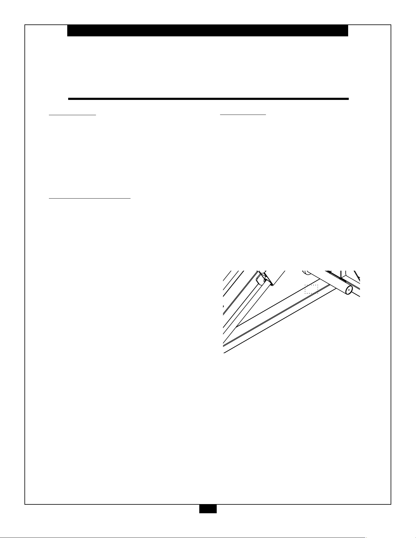
YourS/N#can
befoundhere
↑

6
GCLP100 Parts &Hardware List
Part# Qty Description
A
B
C
D
E
F
G
H
J
K
L
M
N
P
Q
R
S
1
2
3
4
5
6
7
8
9
10
11
12
13
14
15
1
1
1
1
1
1
2
1
1
1
2
1
1
1
1
1
1
1
6
4
11
15
12
2
3
27
12
13
15
1
9
2
FRONT UPRIGHT
BASE FRAME
REAR UPRIGHT
FOOT PLATE SUPPORT FRAME
FOOT PLATE
CENTER FRAME
GUIDE ROD
WEIGHT HORN
CARRIAGE
STEELPLATE,
STEELPLATE,150x48mm
STEELPLATE,160x73mm
BACK REST FRAME
BACK REST TELESCOPING TUBE
BACK REST ADJUSTMENT TUBE
HANDLE BAR
U-BRACKET
M12x85mmHEXHEADBOLT
M10x100mmHEXHEADBOLT
M10x80mmBUTTONHEADCAPSCREW
M10x20HEXHEADBOLT
M8x20mmBUTTONHEADCAPSCREW
M5x3mmSETSCREW
M12 WASHER
M10 LARGE WASHER
M10 WASHER
M10 LOCK WASHER
M8 WASHER
M8 LOCK WASHER
M12 NYLON LOCK NUT
M10 NYLON LOCK NUT
M8 LARGE WASHER

7
GCLP100 Parts &Hardware List
Part# Qty Description
16
17
18
19
20
21
22
23
24
25
26
27
28
29
30
31
32
2
2
4
4
3
2
3
1
2
14
1
1
1
1
2
1
1
RUBBER BUMPER
WEIGHT PLATE BUMPER
RETAINER RING
LINEAR BEARING
HANDLE END CAP
SHORT HAND GRIP
RING
LONG HAND GRIP
SHAFT,
ø12.5x279mm
METALBUSHING,ø19.6xø12.5x10mm
SEAT PAD
BACK PAD
PLASTIC BUSHING
POP PIN
METALBUSHING,
ø28xø25x15mm
TORSION SPRING
SHAFT,
ø22x106mm
45
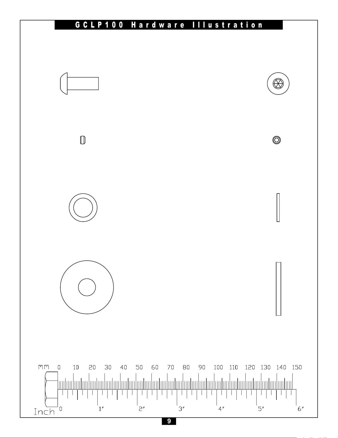
8
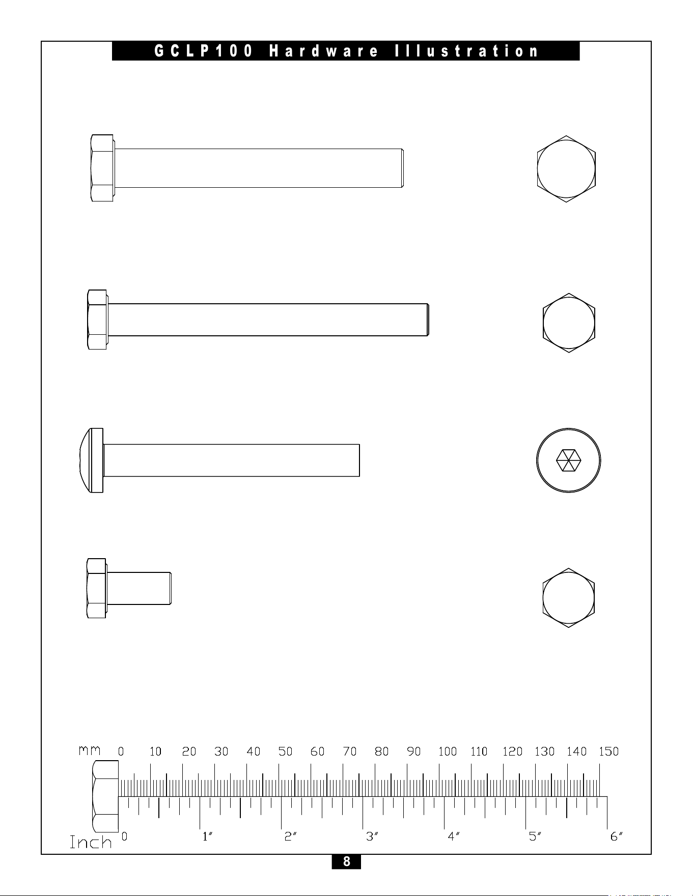
GCLP100 Hardware Illustration
Part#2 HEXHEADBOLTM10x100mm QTY. 6
Part#1 HEXHEADBOLTM12x85mm QTY. 1
Part#3 BUTTONHEADCAPSCREWM10x80mm QTY. 4
Part#4 HEXHEADBOLTM10x20mm QTY. 11
45
9
GCLP100 Hardware Illustration
Part#6 SETSCREWM8x20mm QTY. 12
Part#5 BUTTONHEADCAPSCREWM8x20mm QTY. 15
Part#7 WASHERM12 QTY. 2
Part#8 LARGEWASHERM10 QTY. 3
45
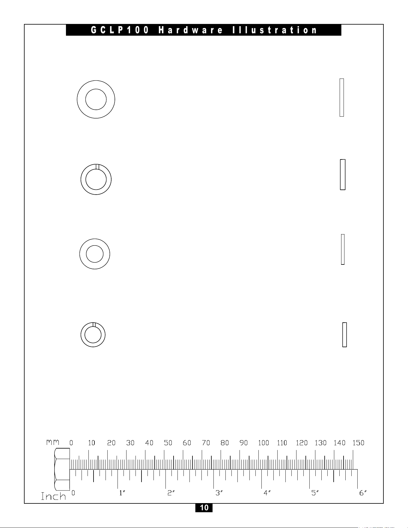
10
GCLP100 Hardware Illustration
Part#10 LOCKWASHERM10 QTY. 12
Part#9 WASHERM10 QTY. 27
Part#11 WASHERM8 QTY. 13
Part#12 LOCKWASHERM8 QTY. 15
45
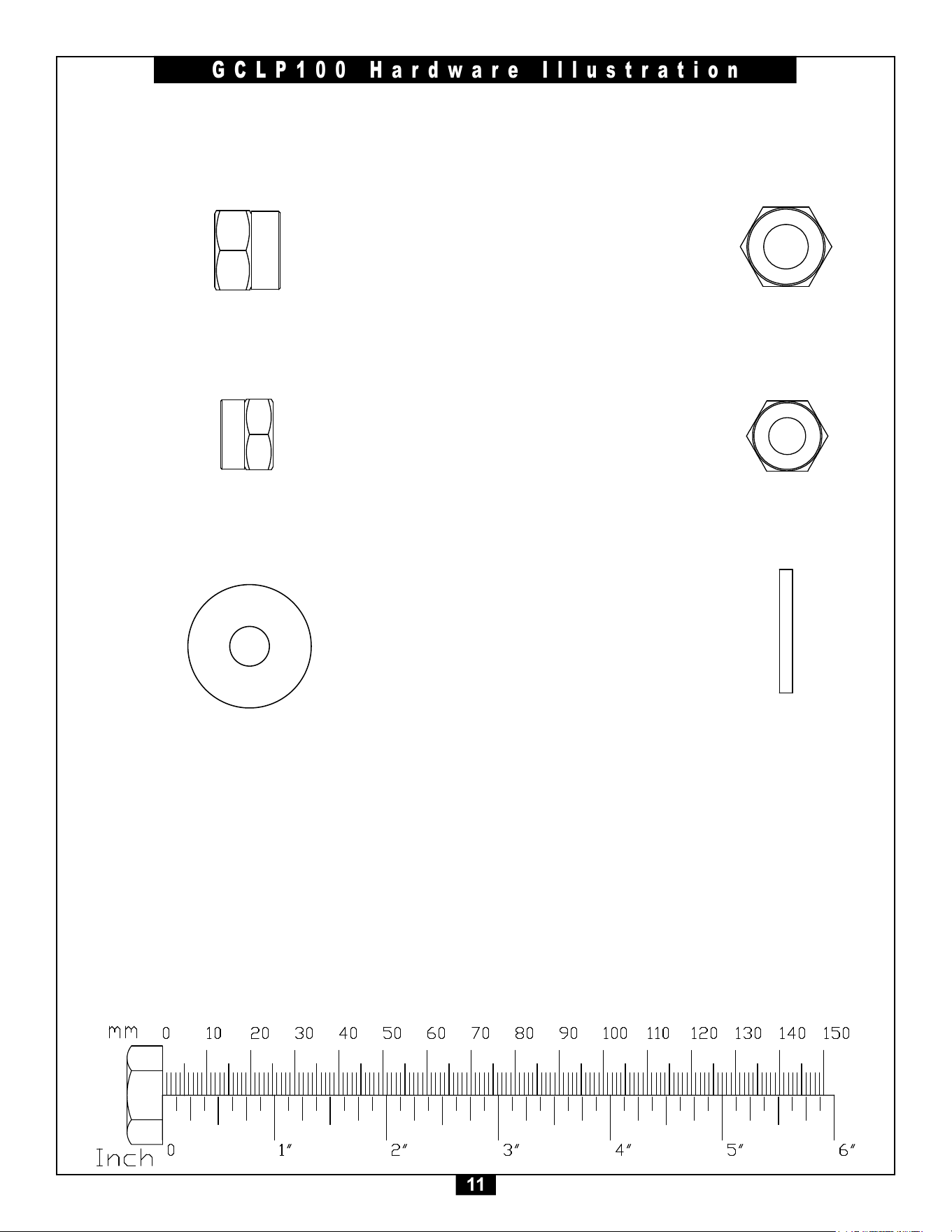
11
GCLP100 Hardware Illustration
Part#14 NYLONLOCKNUTM10 QTY. 9
Part#13 NYLONLOCKNUTM12 QTY. 1
Part#15 LARGEWASHERM8 QTY. 2

12
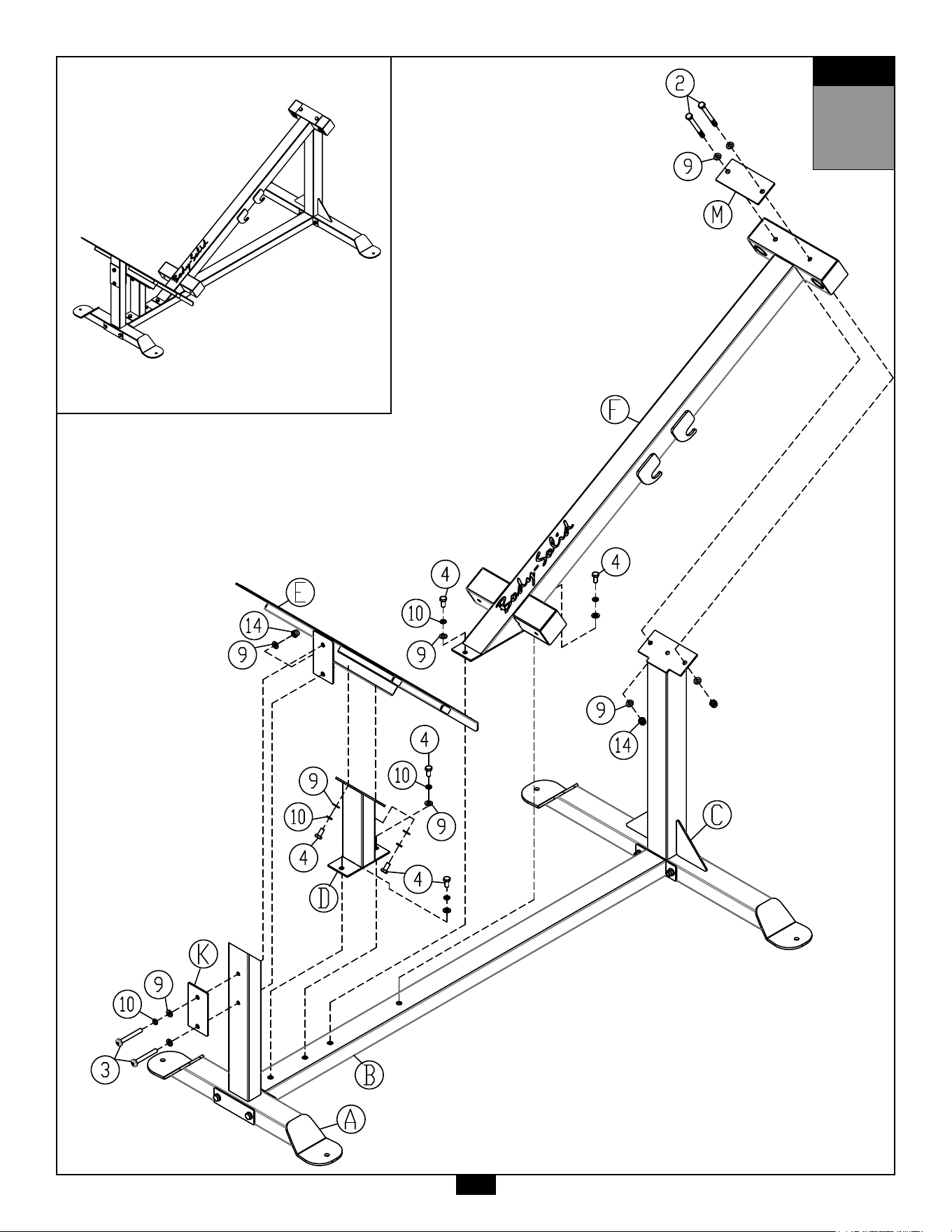
STEP
1
Be careful to assemble all components
in the sequence they are presented.
NOTE:
Finger tighten all hardware in this step. DO NOT wrench tighten until instructed.
Some components may be pre-assembled. Nylon lock nuts will not fully screw onto
bolts, they must be wrench tightened to fully go on.
1A. AttachFrontUpright(A)toBaseFrames(B)using:
2 - (#2) M10x100mm Hex Head Bolt
4 - (#9) M10 Washer
2 - (#14) M10 Nylon Lock Nut
1 - (L) Steel Plate
1B. AttachRearUpright(C)toBaseFrame(B)using:
2 - (#2) M10x100mm Hex Head Bolt
4 - (#9) M10 Washer
2 - (#14) M10 Nylon Lock Nut
1 - (L) Steel Plate
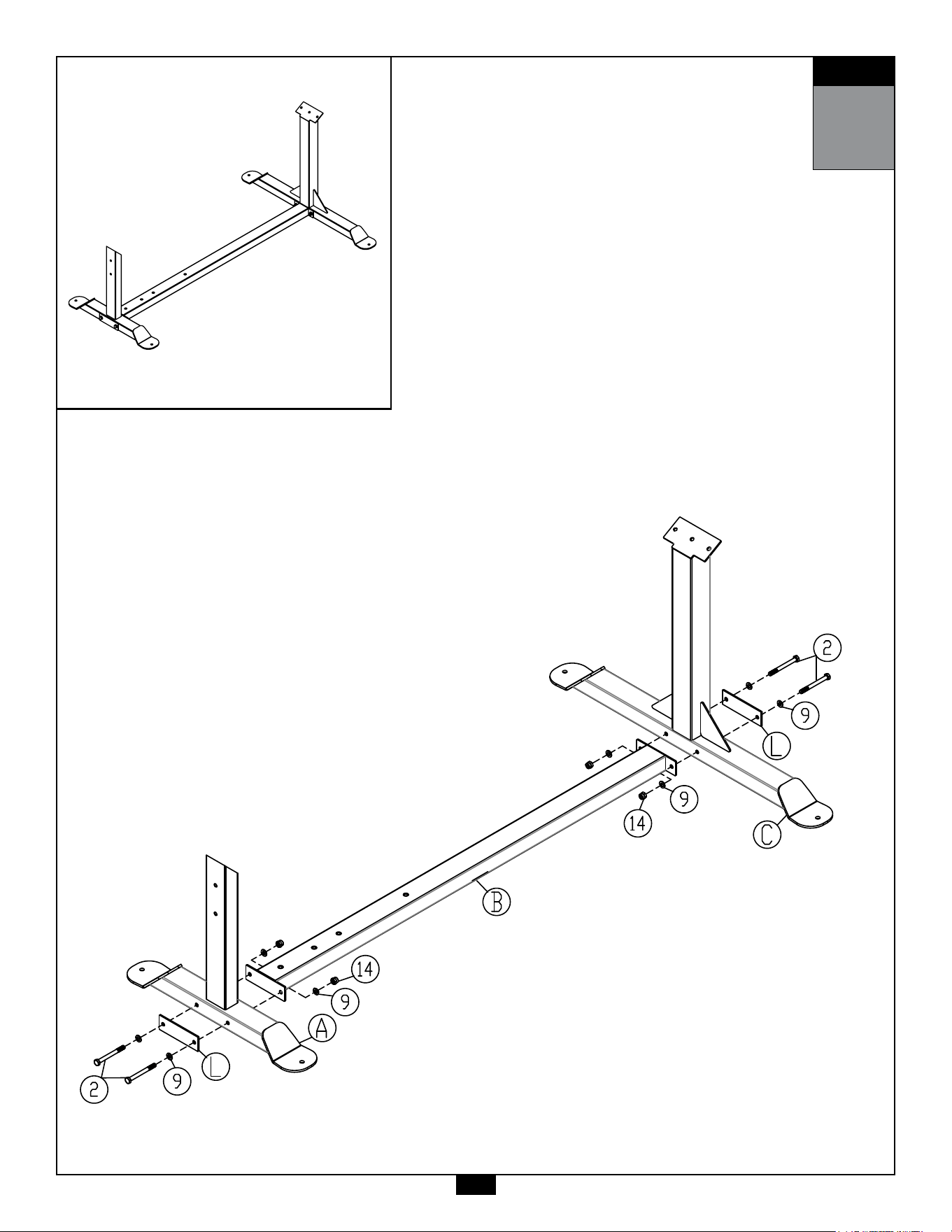
STEP
1
AboveshowsStep1assembledandcompleted.
13

14
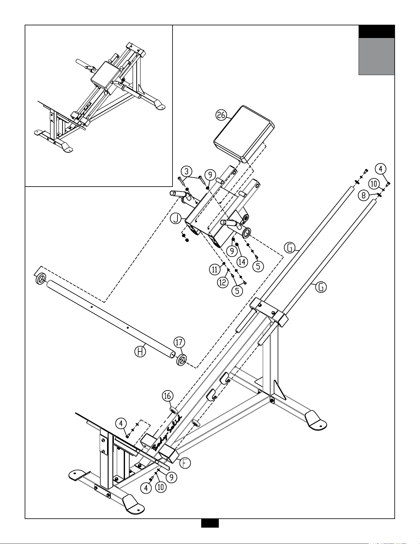
STEP
2
Be careful to assemble all components
in the sequence they are presented.
NOTE:
Wrench tighten ALL hardware at the end of STEP 2C. Some components may be
pre-assembled. Nylon lock nuts will not fully screw onto bolts, they must be wrench
tighten to fully go on.
2A. AttachFootPlateSupportFrame(D)toBaseFrames(B)using:
2 - (#4) M10x20mm Hex Head Bolt
2 - (#9) M10 Washer
2 - (#10) M10 Lock Washer
2B. AttachCenterFrame(F)toBaseFrames(B)using:
2 - (#2) M10x100mm Hex Head Bolt
2 - (#4) M10x20mm Hex Head Bolt
6 - (#9) M10 Washer
2 - (#10) M10 Lock Washer
2 - (#14) M10 Nylon Lock Nut
1 - (M) Steel Plate
2C. AttachFootPlate(E)toFootPlateSupportFrame(D) &Front
Upright(A)using:
2 - (#3) M10x80mm Hex Head Bolt
2 - (#4) M10x20mm Hex Head Bolt
5 - (#9) M10 Washer
3 - (#10) M10 Lock Washer
1 - (#14) M10 Nylon Lock Nut
1 - (K) Steel Plate
STEP
2
AboveshowsStep2assembledandcompleted.
15

16
STEP
3
Be careful to assemble all components
in the sequence they are presented.
NOTE:
Wrench tighten ALL hardware at the end of STEP 3E. Some components may be
pre-assembled. Nylon lock nuts will not fully screw onto bolts, they must be wrench
tighten to fully go on.
3A. AttachSeatPad(#26)toCarriage(J)using:
3 - (#5) M8x20mm Button Head Cap Screw
3 - (#11) M8 Washer
3 - (#12) M8 Lock Washer
3B. InsertGuideRods(G)halfwayintoCenterFrame(F).
3C. InstallCarriage(J)ontoGuideRods (G).
3D. InserttheRubberBumpers(#16) ontoGuideRods(G).
3E. AttachGuideRods(G)toCenterFrame(F)using:
4 - (#4) M10x20mm Hex Head Bolt
2 - (#9) M10 Washer
2 - (#8) M10 Large Washer
4 - (#10) M10 Lock Washer
3F. AttachWeightHorn(H)toCarriage(J)using:
2 - (#3) M10x80mm Button Head Cap Screw
4 - (#9) M10 Washer
2 - (#14) M10 Nylon Lock Nut
3G. InserttheWeightPlateBumpers(#17) ontoWeightHorn(H).
STEP
3
AboveshowsStep3assembledandcompleted.
17

18
STEP
4
Be careful to assemble all components
in the sequence they are presented.
NOTE:
Wrench tighten ALL hardware at the end of STEP 4G. Some components may be
pre-assembled. Nylon lock nuts will not fully screw onto bolts, they must be wrench
tighten to fully go on.
4A. AttachBackRestFrame(N)toCarriage(J)using:
2 - (#5) M8x20mm Button Head Cap Screw
2 - (#11) M8 Washer
2 - (#12) M8 Lock Washer
6 - (#25) Metal Bushing
1 - (#24) SHAFT
4B. AttachBackRestAdjustmentTube(Q)toCarriage(J)using:
2 - (#5) M8x20mm Button Head Cap Screw
2 - (#11) M8 Washer
2 - (#12) M8 Lock Washer
6 - (#25) Metal Bushing
1 - (#24) SHAFT
4C. InsertBackRestTelescopingTube(P) intoBackRestAdjustment
Tube (Q).
4D. ScrewPopPin(#29) intoBackRestAdjustmentTube (Q).
4E. AttachBackRestTelescopingTube(P)toBackRestFrame(N) using:
1 - (#1) M12x90mm Hex Head Bolt
2 - (#7) M12 Washer
1 - (#13) M12 Nylon Lock Nut
2 - (#25) Metal Bushing
4F. AttachBackPad(#27)toBackRestFrame(N) using:
4 - (#5) M8x20mm Button Head Cap Screw
4 - (#11) M8 Washer
4 - (#12) M8 Lock Washer
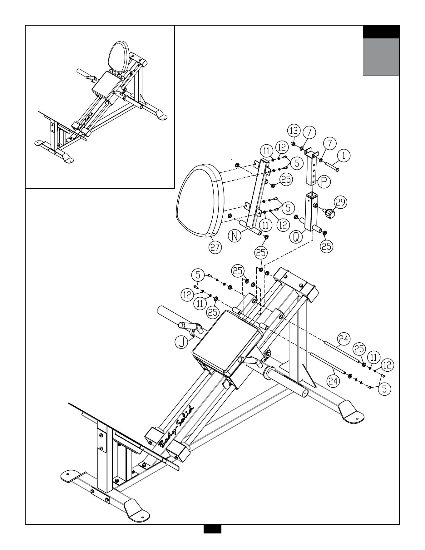
STEP
4
AboveshowsStep4assembledandcompleted.
19

20
STEP
5
Be careful to assemble all components
in the sequence they are presented.
NOTE:
Wrench tighten ALL hardware at the end of STEP 5B. Some components may be
pre-assembled. Nylon lock nuts will not fully screw onto bolts, they must be wrench
tighten to fully go on.
5A. AttachUBracket(S) &HandleBar (R) toCarriage(J)inthe
sequenceshownintheStep5Drawingusing:
1 - (#4) M10x20mm Hex Head Bolt
1 - (#8) M10 Large Washer
1 - (#10) M10 Lock Washer
2 - (#5) M8x20mm Button Head Cap Screw
2 - (#11) M8 Washer
2 - (#12) M8 Lock Washer
2 - (#30) Metal Bushing
1 - (#31) Torsion Spring
NOTE #1:
- Assembling the U Bracket Assembly (S) will require a torque pre-load on
Torsion Spring (31).
- Insert the straight dog-ear of the Spring (31) into the hole on the bracket
of the Seat Frame (J).
- Slide the left side of the U Bracket Assembly (S) into the j-hook end of
the Torsion Spring (31).
- As you slide Handle Bar (R) into place, you will need to push on the body
of the Torsion spring to align with shaft pushing through.
- Drawing shows the Assembled View of the U-Bracket & Handle Bar.
5B. AttachShaft (#32)toUBracket(S)using:
2 - (#5) M8x20mm Button Head Cap Screw
2 - (#15) M8 Large Washer
2 - (#12) M8 Lock Washer
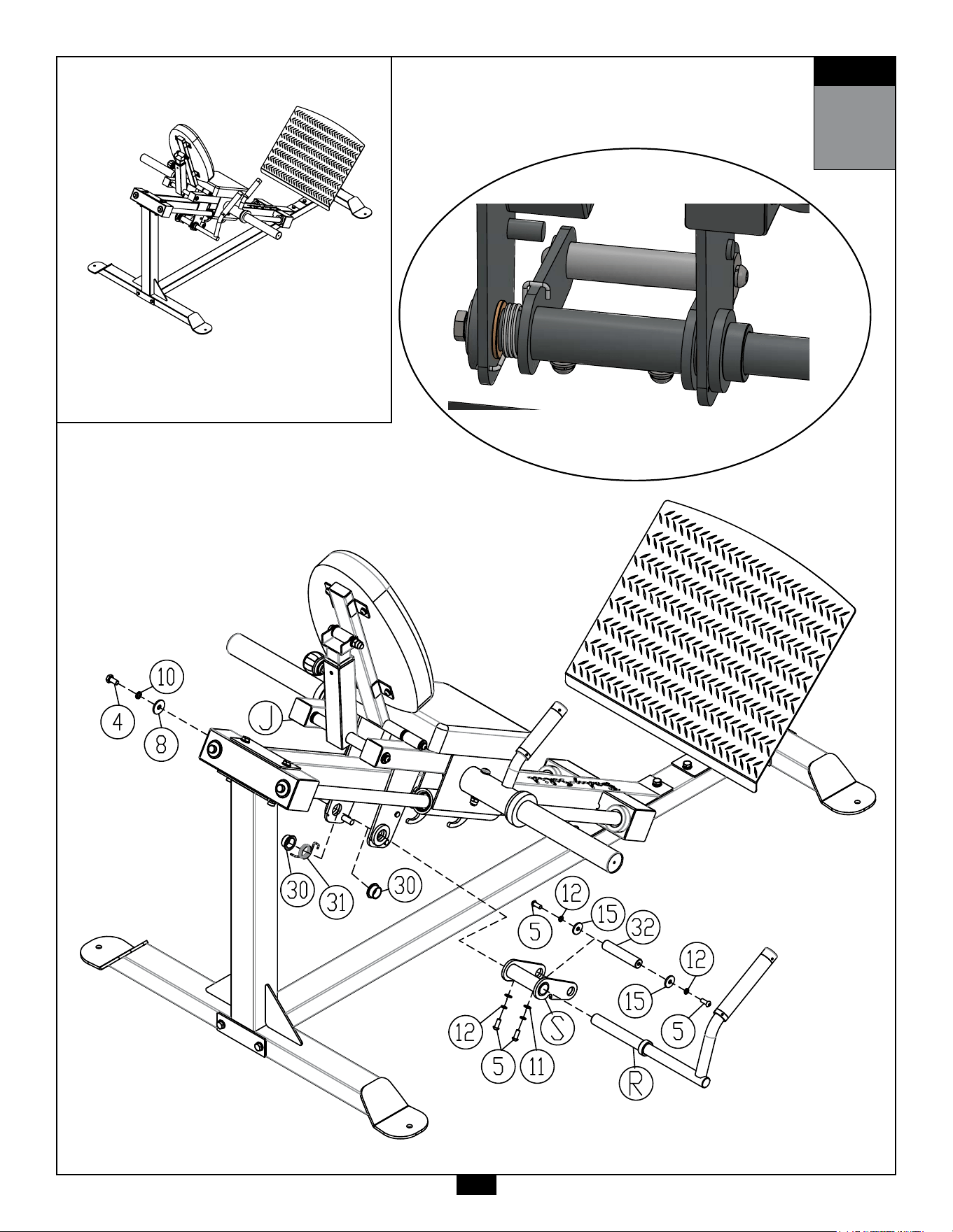
STEP
5
AboveshowsStep5assembledandcompleted.
21
Note #1

45
22
Notes
23
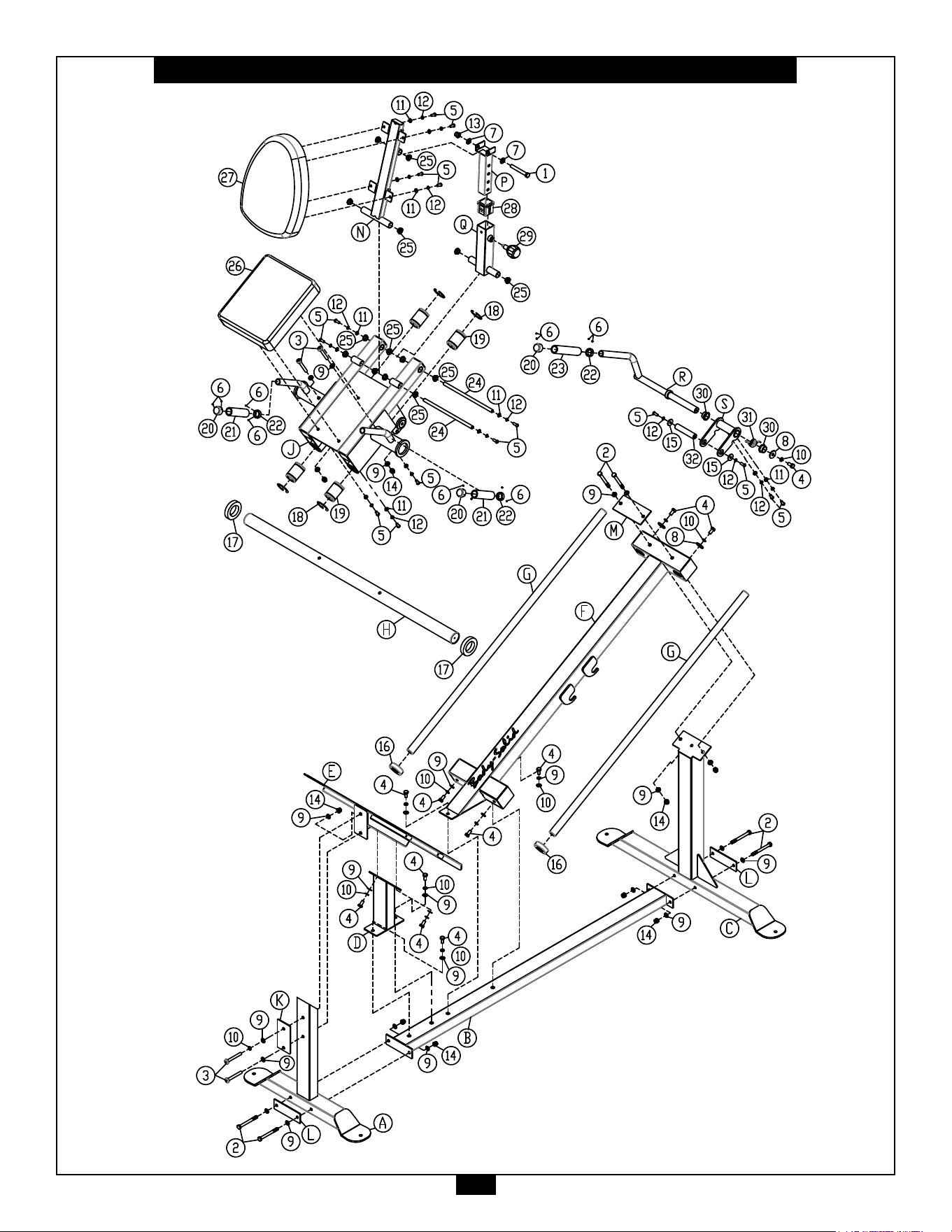
GCLP100 Exploded View

1900S.DesPlainesAve.
ForestPark,IL60130
Phone:(708)427-3555
Fax:(708)427-3556
Hours:M-F8:30-5:00CST
www.bodysolid.com
Copyright 2009. Body-Solid. All rights reserved. Body-Solid reserves the right to change design and specications when we feel it will improve the product.
Body-Solid machines maintain several patented and patent pending features and designs. All rights reserved on all design patents and utility patents.
PLEASE WRITE YOUR SERIAL NUMBER IN THE BOXES BELOW
S/N#
016200-��-��-����-����
GCLP100