
&
A s s e m b l y I n s t r u c t i o n s
O W N E R ’ S M A N U A L
by
by
®
®
v. 042910
O W N E R ` S M A N U A L
A s s e m b l y I n s t r u c t i o n s
&
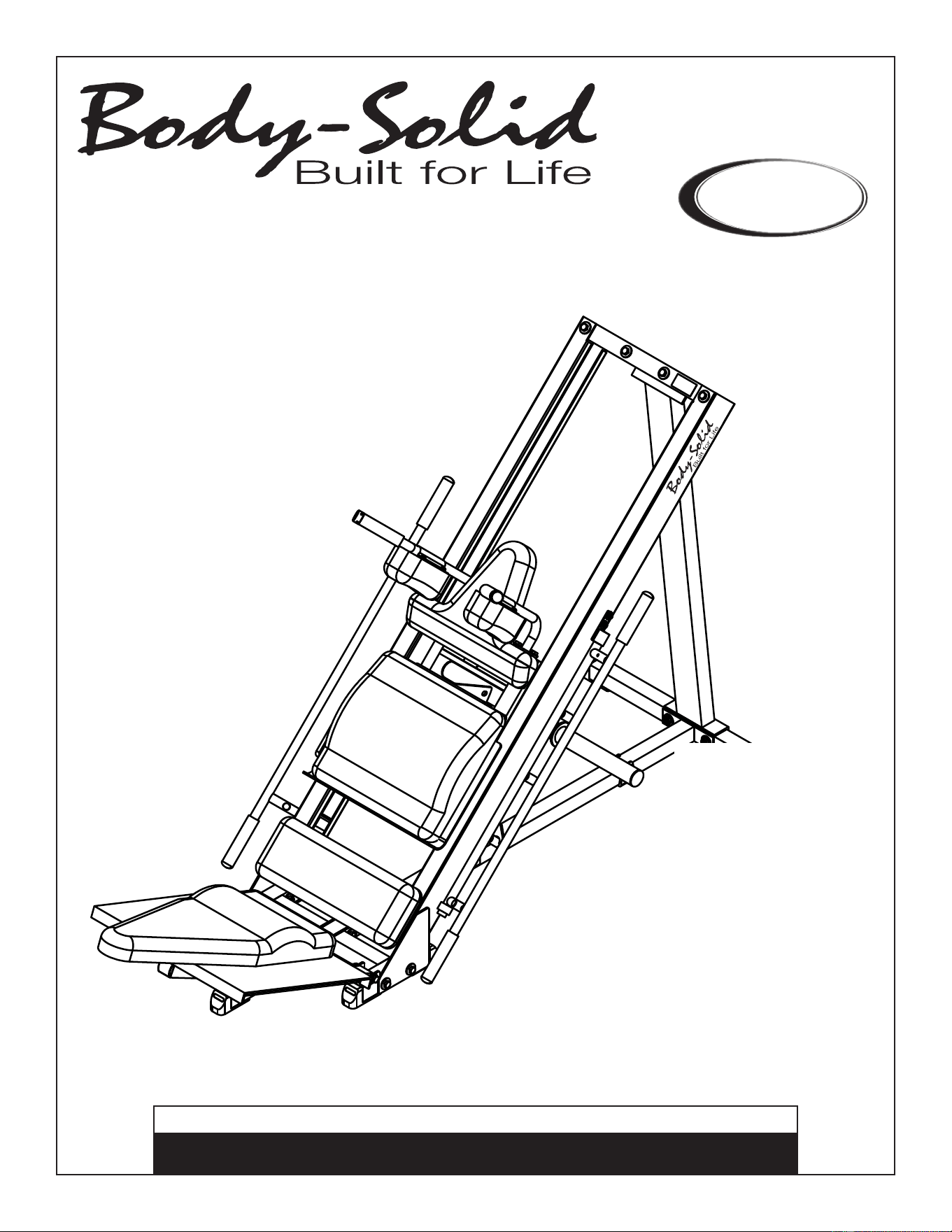
GLPH1100.3
by
by
®
®
T
able of Contents
Quick Workout Reference. . . . . . . . . . . . . . p. 2
Reference Drawings. . . . . . . . . . . . . . . . . . . p. 3
Important Safety Instructions. . . . . . . . . . . p. 4
Before You Begin. . . . . . . . . . . . . . . . . . . . . . p. 5
Dimensions. . . . . . . . . . . . . . . . . . . . . . . . . . . p. 6
Safety Guidelines. . . . . . . . . . . . . . . . . . . . . . p. 7
Preparations. . . . . . . . . . . . . . . . . . . . . . . . . . p. 8
Assembly Instructions. . . . . . . . . . . . . . . . . p. 9-25
Warning, Safety & Maintenance. . . . . . . . . p. 26-27
Exercise Tips. . . . . . . . . . . . . . . . . . . . . . . . . p. 28-47
Torsion Spring Removal . . . . . . . . . . . . . . . p. 48-50
Torsion Spring Installation . . . . . . . . . . . . . p. 51-53
Mainframe Parts List. . . . . . . . . . . . . . . . . . . p. 54
Hardware List. . . . . . . . . . . . . . . . . . . . . . . . . p. 55
Hardware (To Scale). . . . . . . . . . . . . . . . . . . p. 56-59
Exploded View Diagram. . . . . . . . . . . . . . . . p. 60-61
by
by
®
®
GLPH1100
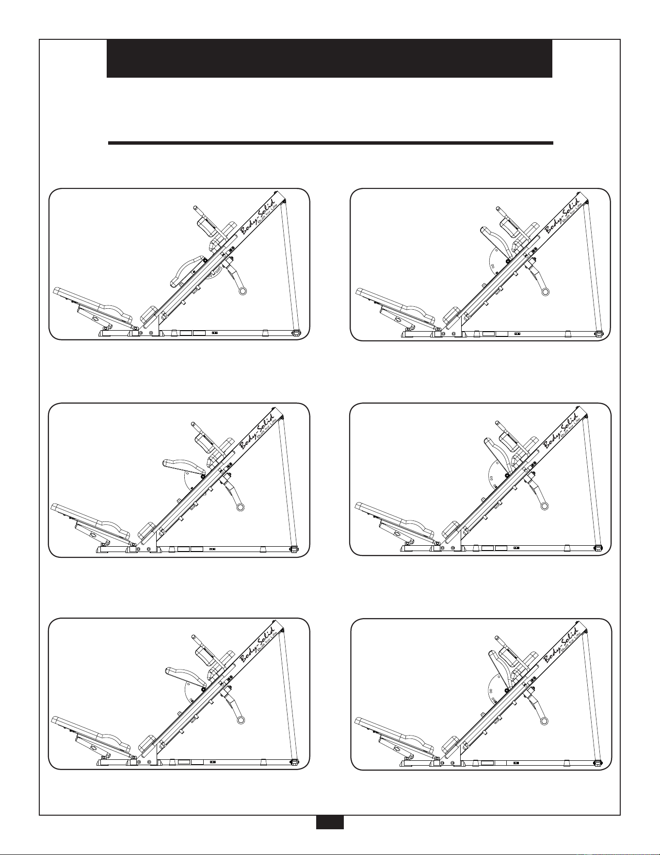
Q u i c k W o r k o u t R e f e r e n c e
2
Calf Press Diagram 1
Calf Press Diagram 2
Calf Press Diagram 3
Leg Press Diagram 1
Leg Press Diagram 2
Leg Press Diagram 3
Diagram 1
Squat Press
Diagram 2
Calf Press - Position 1
Diagram 3
Calf Press - Position 2
Diagram 4
Leg Press - Position 1
Diagram 5
Leg Press - Position 2
Diagram 6
Leg Press - Position 3
The GLPH1100 has several adjustments that enable many different and effective workouts.
Please see below for a collection of GLPH1100 adjustment references.
by
by
®
®
by
by
®
®
by
by
®
®
by
by
®
®
by
by
®
®
by
by
®
®
G L P H 1 1 0 0
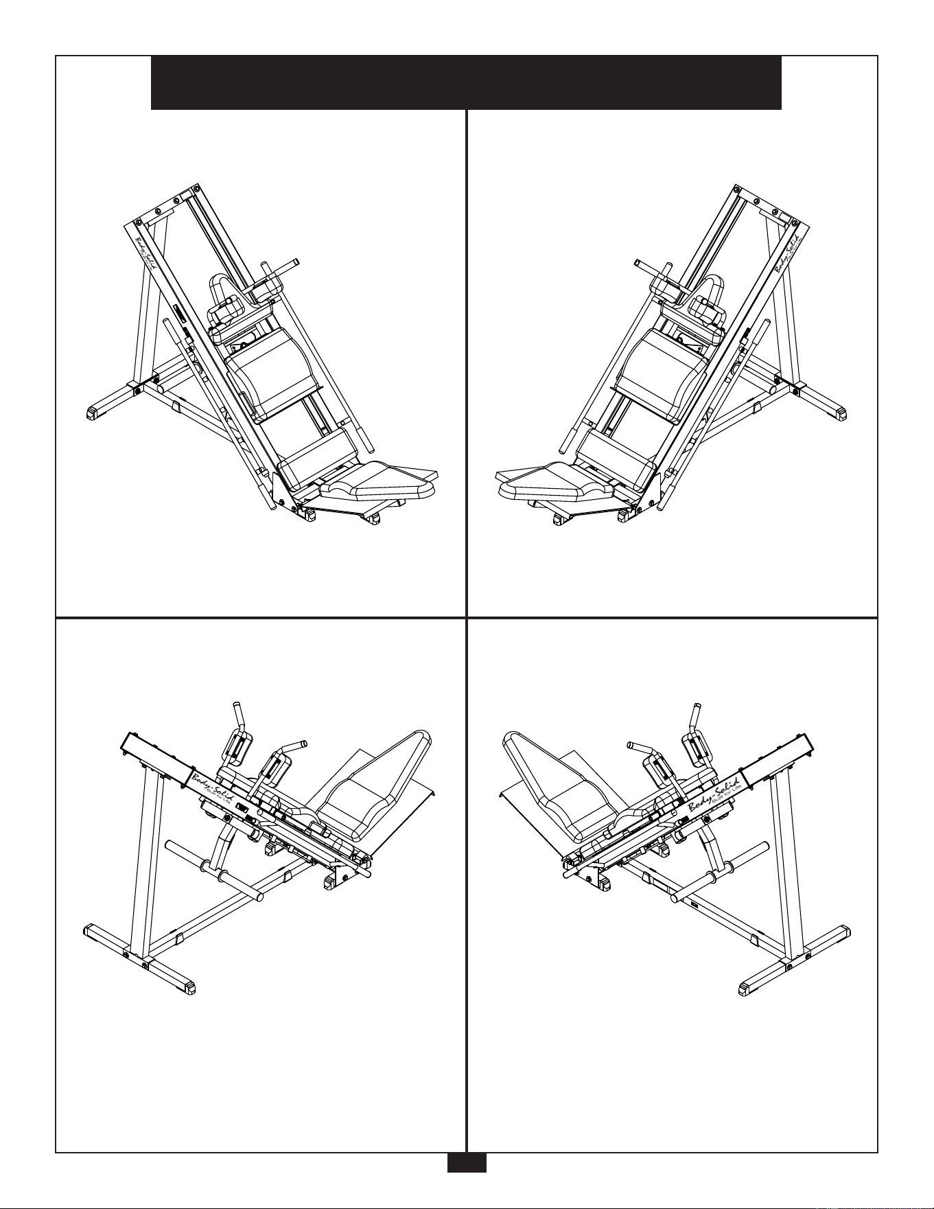
R e f e r e n c e D r a w i n g s
3
Note: Due to continuing product improvements, specifications and designs are subject to change
without notice.
Even though we have prepared this manual with extreme care, neither the publisher nor the
author can accept responsibility for any errors in, or omission from, the information given.
G L P H 1 1 0 0
R e f e r e n c e D r a w i n g s
Note: Due to continuing product improvements, specifications and designs are subject to
change without notice.
Even though we have prepared this manual with extreme care, neither the publisher nor the
author can accept responsibility for any errors in, or omission from, the information given.
by
by
®
®

I m p o r t a n t S a f e t y I n s t r u c t i o n s
4
Before beginning any fitness program, you should obtain a complete physical examination from your physician.
Il est conseille de subir un examen medical complet avant d’entreprendre tout programme d’exercise.
Si vous avez des etourdissements ou des faiblesses, arretez les exercices immediatement.
Antes de comenzar cualquier programma de ejercicios, deberias tener un examen fisico con su doctor.
When using exercise equipment, you
should always take basic precautions,
including the following:
m Read all instructions before using the GLPH1100.
These instructions are written to ensure your safety
and to protect the unit.
m Do not allow children on or near the equipment.
m Use the equipment only for its intended purpose
as described in this guide. Do not use accessory
attachments that are not recommended by the
manufacturer. Such attachments might cause
injuries.
m Wear proper exercise clothing and shoes for your
workout, no loose clothing.
m Use care when getting on or off the unit.
m Do not overexert yourself or work to exhaustion.
m If you feel any pain or abnormal symptoms, stop
your workout immediately and consult your
physician.
m Never operate the unit when it has been dropped or
damaged. Return the equipment to a service
center for examination and repair.
m Never drop or insert objects into any opening in
the equipment.
m Do not use the equipment outdoors or near water.
Personal Safety During Assembly
m It is strongly recommended that a qualified dealer
assemble the equipment.
Assistance is required.
m Before beginning assembly, please take the time
to read the instructions thoroughly.
m Read each step in the assembly instructions and
follow the steps in sequence. Do not skip ahead.
If you skip ahead, you may learn later that you
have to disassemble components and that you
may have damaged the equipment.
m Assemble and operate the GLPH1100 on a solid,
level surface. Locate the unit a few feet from the
walls or furniture to provide easy access.
The GLPH1100 is designed for your enjoyment. By fol-
lowing these precautions and using common sense, you
will have many safe and pleasurable hours of healthful
exercise with your Body-Solid GLPH1100.
After assembly, you should check all functions to
ensure correct operation. If you experience problems,
first recheck the assembly instructions to locate any
possible errors made during assembly. If you are unable
to correct the problem, call the dealer from whom you
purchased the machine or call 1-800-556-3113 for the
dealer nearest you.
Obtaining Service
Please use this Owner’s Manual to make sure that all
parts have been included in your shipment. When
ordering parts, you must use the part number and
description from this Owner’s Manual. Use only
Body-Solid replacement parts when servicing this
machine. Failure to do so will void your warranty and
could result in personal injury.
For information about product operation or service,
check out the official Body-Solid website at
www.bodysolid.com or contact an authorized
Body-Solid dealer or a Body-Solid factory-authorized
service company or contact Body-Solid customer
service at one of the following:
Toll Free: 1-800-556-3113
Phone: 1-708-427-3555
Fax: 1-708-427-3556
Hours: M-F 8:30-5:00 CST
E-Mail: [email protected]
Or write to: Body-Solid, Inc.
Service Department
1900 S. Des Plaines Ave.
Forest Park, IL 60130 USA
Retain this Owner’s Manual for future
reference. Part numbers are required when
ordering replacement parts.

5
B e f o r e Y o u B e g i n
Thank you for purchasing the GLPH1100. This gym is part of the Body-Solid line of quality strength
training machines, which let you target specific muscle groups to achieve better muscle tone and
overall body conditioning. To maximize your use of the equipment please study this Owner’s Man-
ual thoroughly.
Unpacking the Equipment
The GLPH1100 is carefully tested and inspected before
shipment. Body-Solid ships the unit in several pieces that
require assembly. Ask for assistance during the assembly
process.
Carefully unpack the boxes and lay the pieces on the
floor near the area where you plan to use the equipment.
Be careful to assemble all components in the
sequence presented in this guide.
If any items are missing, contact the dealer from whom
you purchased the unit or call 1-800-556-3113 for the
dealer nearest you.
Body-Solid continually seeks ways to improve the performance, specifications and product manuals in order to ensure that only
superior products are released from our factories. Please take the time to carefully read through this manual thoroughly. Instructions
contained in this document are not intended to cover all details or variations possible with Body-Solid equipment, or to cover every
contingency that may be met in conjunction with installation, operation, maintenance or troubleshooting of the equipment. Even
though we have prepared this manual with extreme care, neither the publisher nor the author can accept responsibility for any errors
in, or omission from, the information given. Should additional information be required, or should situations arise that are not covered
by this manual, the matter should be directed to your local Body-Solid representative, or the Service Department at Body-Solid Inc.
in Forest Park, Illinois.
Any Questions?
Call (800) 556-3113
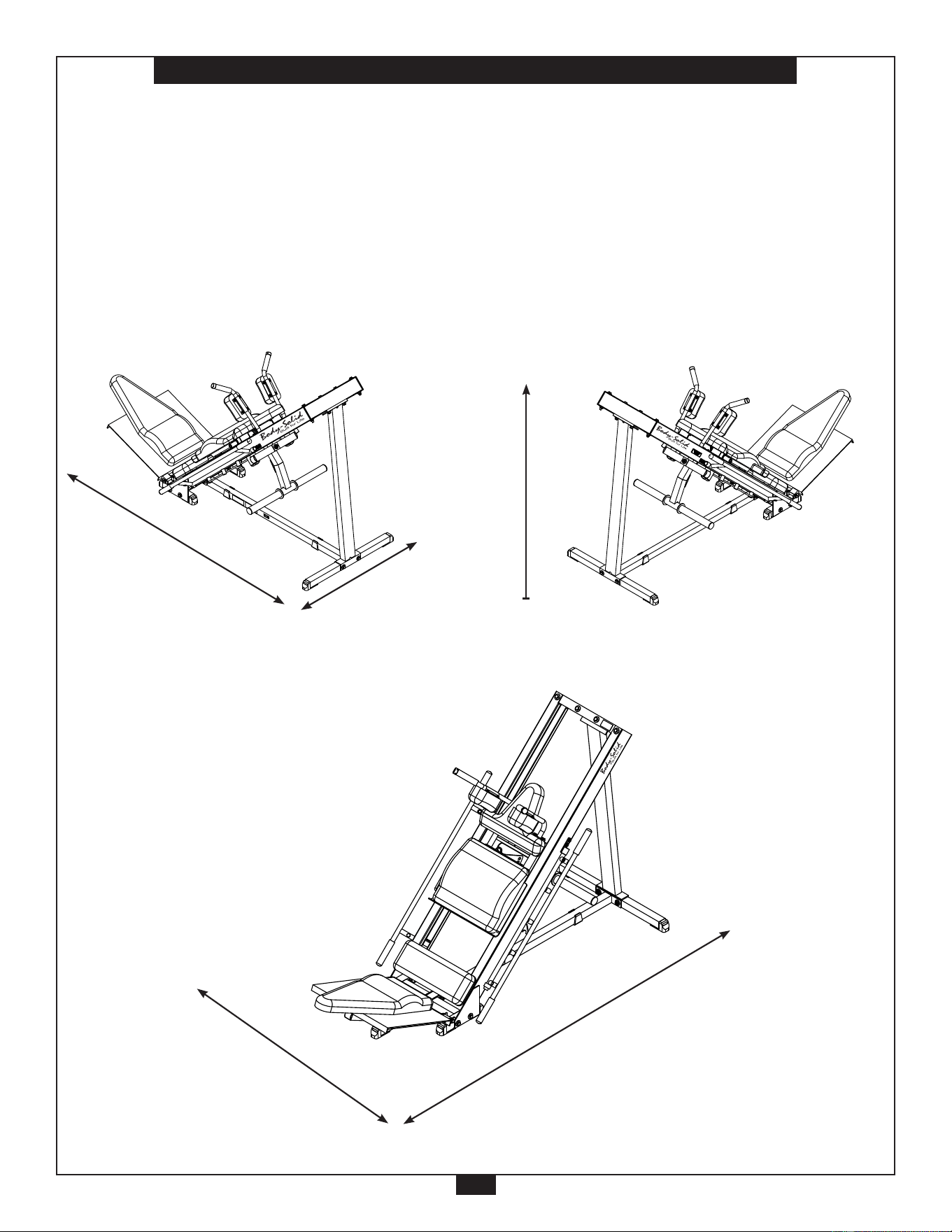
D i m e n s i o n s
6
The room layout diagram below will help you decide the best placement for your GLPH1100.
The dimensions of the GLPH1100 are: Width 2’ 11” X Length 7’8”.
The ceiling height requirement for the GLPH1100 is 4’7”.
The usage space is: Width 5’ X Length 10’ (The usage space is the overall space needed for operation).
The usage space needed for the GLPH1100 could be more, depending on the user.
Minimum Usage Space
2’ 11”
7’ 8”
4’ 7”
Suggested Usage Space
10’
5’
G L P H 1 1 0 0
R e f e r e n c e D r a w i n g s
Note: Due to continuing product improvements, specifications and designs are subject to
change without notice.
Even though we have prepared this manual with extreme care, neither the publisher nor the
author can accept responsibility for any errors in, or omission from, the information given.
by
by
®
®

7
S a f e t y G u i d e l i n e s
Successful resistance training programs have one prominent feature in common... safety. Resistance
training has some inherent dangers, as do all physical activities. The chance of injury can be greatly
reduced or completely removed by using correct lifting techniques, proper breathing, maintaining equip-
ment in good working condition, and by wearing the appropriate clothing.
m It is highly recommended that you consult your physician before beginning any exercise
program. This is especially important for individuals over the age of 35, or persons with
pre-existing health problems.
m Always warm up before starting a workout. Try to do a total body warm up before you
start. It is especially important to warm up the specific muscle groups you are going to be
using. This can be as simple as performing a warm up set of high repetitions and light
weight for each exercise.
m Use proper form. Focus on only working the muscle groups intended for the exercise you
are doing. If there is strain elsewhere, you may need to re-evaluate the amount of weight
that is involved with the lift. Keeping proper form also includes maintaining control
through an entire range of motion.
m Breath properly. Inhale during the eccentric phase of the exercise, and exhale during the
lifting, or concentric phase. Never hold your breath during any part of an exercise.
m Always wear the appropriate clothing and shoes when exercising. Wearing comfortable
athletic shoes with good support and loose fitting, breathable clothing will reduce the risk
of injury.
m Maintaining equipment in proper operating condition is of utmost importance for a safe
resistance training program. Pulleys and cables should be checked for wear frequently
and replaced as needed. Equipment should be lubricated as indicated by the
manufacturer.
m Read and study all warning labels on this machine. It is absolutely necessary that you
familiarize yourself and all others with the proper operation of this machine prior to use.
m Keep hands, limbs, loose clothing and long hair well out of the way of all moving parts.
m Do not attempt to lift more weight than you can control safely.
m Inspect the machine daily for loose or worn parts. If a problem is found do not allow the
machine to be used until all parts are tightened or worn or defective parts are repaired or
replaced.

P r e p a r a t i o n s
8
CAUTION: To set up this unit, you will need assistance.
Do not attempt assembly by yourself.
You must review and follow the instructions in this Owner’s Manual. If you do not assemble and use the
GLPH1100 according to these guidelines, you could void the Body-Solid warranty.
Required Tools
The basic tools that you must obtain before assembling
the GLPH1100 include but are not limited to:
m Metric Allen Key Set
m Standard Allen Key Set
m Standard Wrench Set
m Metric Wrench Set
m Adjustable Wrench
m Screwdriver (standard and/or phillips)
m Rubber Mallet
m Silicone Spray Oil
Installation Requirements
Follow these installation requirements when assembling
the GLPH1100:
Set up the GLPH1100 on a solid, flat surface. A smooth,
flat surface under the machine helps keep it level. A
level machine has fewer malfunctions.
Provide ample space around the machine. Open
space around the machine allows for easier access.
Insert all bolts in the same direction. For aesthetic
purposes, insert all bolts in the same direction unless
specified (in text or illustrations) to do otherwise.
Leave room for adjustments. Tighten fasteners such as
bolts, nuts, and screws so the unit is stable, but leave
room for adjustments. Do not fully tighten fasteners
until instructed in the assembly steps to do so.
Fill out and mail the warranty card.
The GLPH1100 unit comes in five boxes. Be careful to
assemble components in the sequence presented in
this guide.
NOTE: With so many assembled parts, proper
alignment and adjustment is critical. While
tightening the nuts and bolts, be sure to leave
room for adjustments.
CAUTION: Obtain assistance! Do not attempt to
assemble the GLPH1100 by yourself.
Review the Installation Requirements
before proceeding with the following
steps.
9
A s s e m b l y I n s t r u c t i o n s
Assembly of the GLPH1100 takes professional installers about 2 hours to complete. If this is the first
time you have assembled this type of equipment, plan on significantly more time.
Professional installers are highly recommended!
However, if you acquire the appropriate tools, obtain assistance, and follow the assembly steps sequen-
tially,
the process will take time, but is fairly easy.
Assembly Tips
Read all “Notes” on each page before beginning each
step.
While you may be able to assemble the GLPH1100 using
the illustrations only, important safety notes and other
tips are included in the text.
Some pieces may have extra holes that you will not use.
Use only those holes indicated in the instructions and
illustrations.
Do not fully tighten bolts until instructed to do so.
NOTE: After assembly, you should check all functions
to ensure correct operation. If you experience
problems,rstrechecktheassemblyinstructions
to locate any possible errors made during assembly.
If you are unable to correct the problem, call the
dealer from whom you purchased the machine or
call 1-800-556-3113 for the dealer nearest you.
IMPORTANT!
Before you begin you should look at the quick reference
guide that shows all hardware parts (in actual size) along
with the corresponding key numbers on the assembly
instructions.
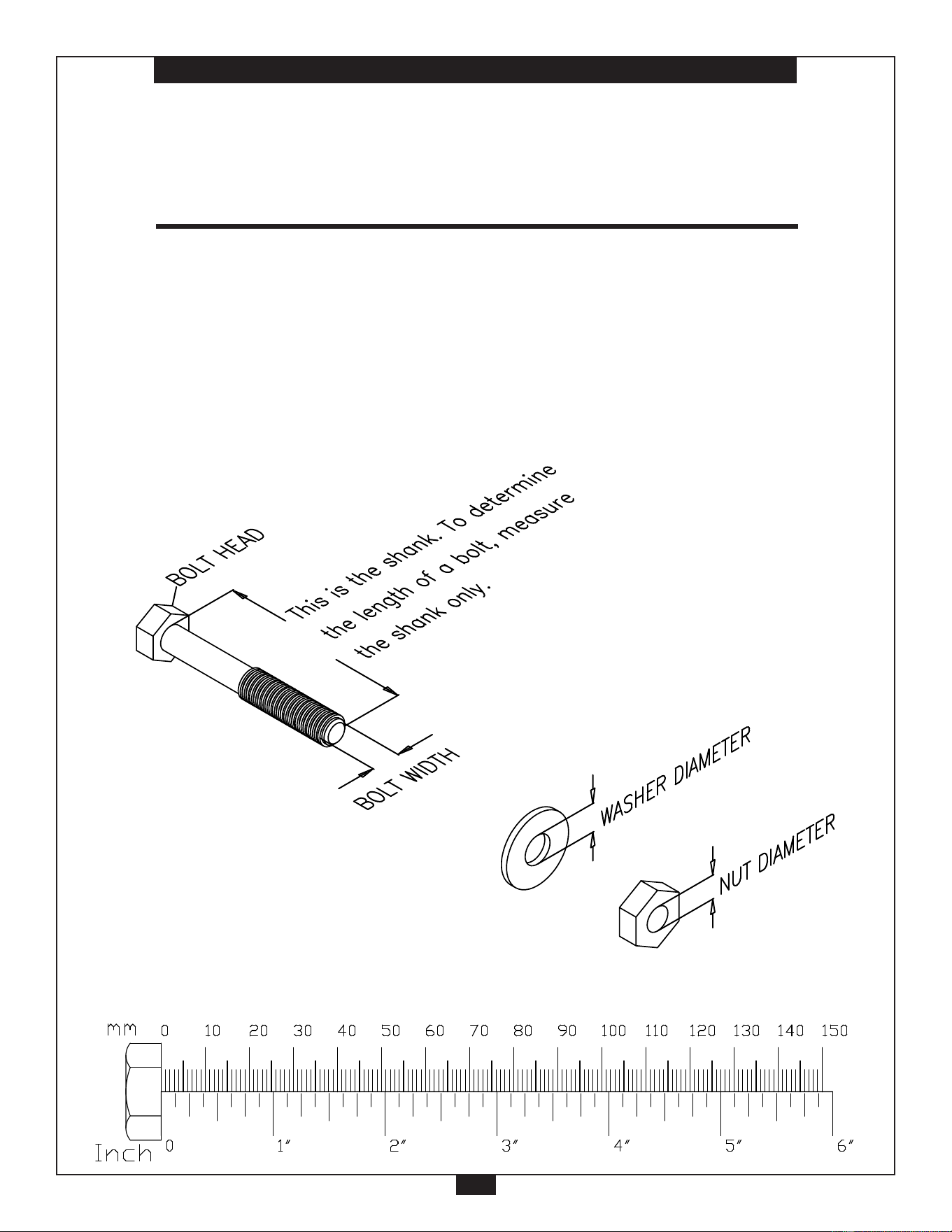
NOTE: To find out the length of a particular bolt,
measure its shank (the long, narrow part
beneath the head). Refer to the following
diagram:

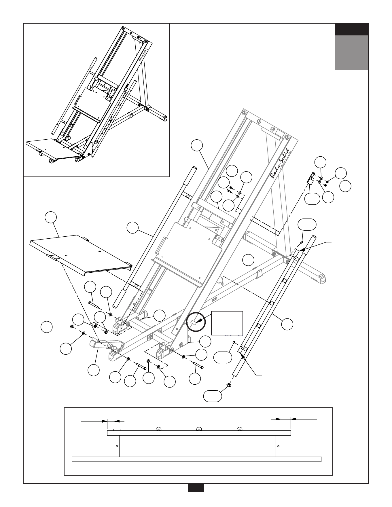
10
S T E P
1
Be careful to assemble all components
in the sequence they are presented.
NOTE: Tighten all hardware at the end of this step.
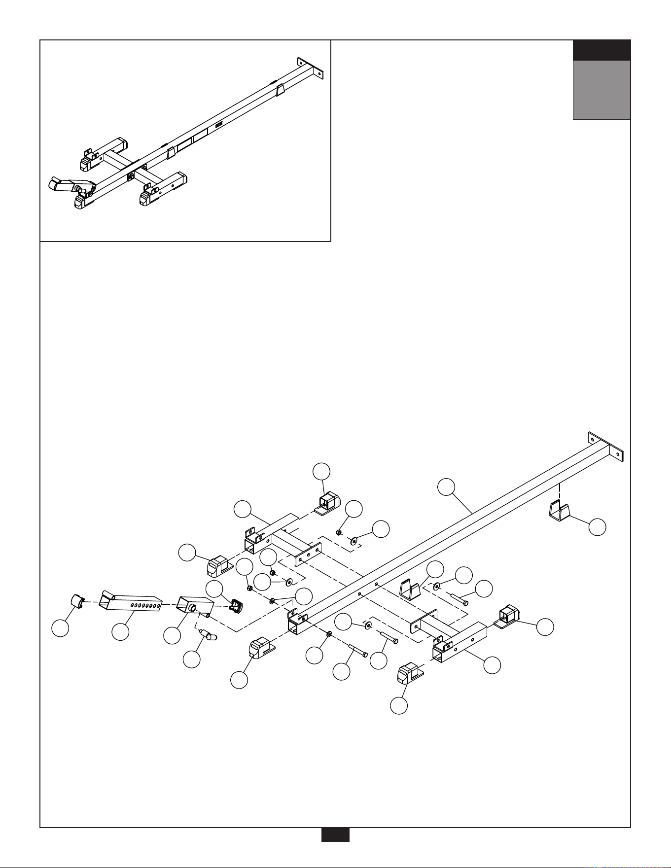
A. Attach both Base Caps (34) to Base Frame (A) at the positions shown.
B. Insert Foot Cap (32) into Base Frame (A).
C. Insert two Foot Caps (32) into Left Stabilizer Frame (D).
D. Insert two Foot Caps (32) into Right Stabilizer Frame (C).
E. Insert two End Caps (28) into Selector Insert Frame (N).
F. Make sure Pop-Pin (17) is preinstalled into Selector Tube (O).
G. Set Selector Insert Frame (N) into Selector Tube (O) then secure Selector Tube (O) to Base
Frame (A) using:
One 3 (M12x90 hex head bolt)
Two 21 (M12x25 washer)
One 18 (M12 nylon lock nut)
H. Connect Right Stabilizer Frame (C) and Left Stabilizer Frame (D) to Base Frame (A) using:
Two 2 (M12x80 hex head bolt)
Four 22 (M12x34 washer)
Two 18 (M12 nylon lock nut)
11
S T E P
1
Above shows Step 1 assembled and completed.
S T E P
Above shows STEP 1
assembled and completed
5
D7
D5
D5
D
B1X2
C2X2
B1
C1
C1
A3
C2X2
D7
A2X2
D5
D5
C
OD1X2
N
A
D5
A17
S T E P
Above shows STEP 1
assembled and completed
5
34
32
21
34
32
32
28
N
O
17
D
18
21
22
18
28
3
22
2
2
32
C
32
18
22
A
22

12
S T E P
2
Be careful to assemble all components
in the sequence they are presented.
NOTE: Tighten all hardware at the end of this step.
Some components may be pre-installed.
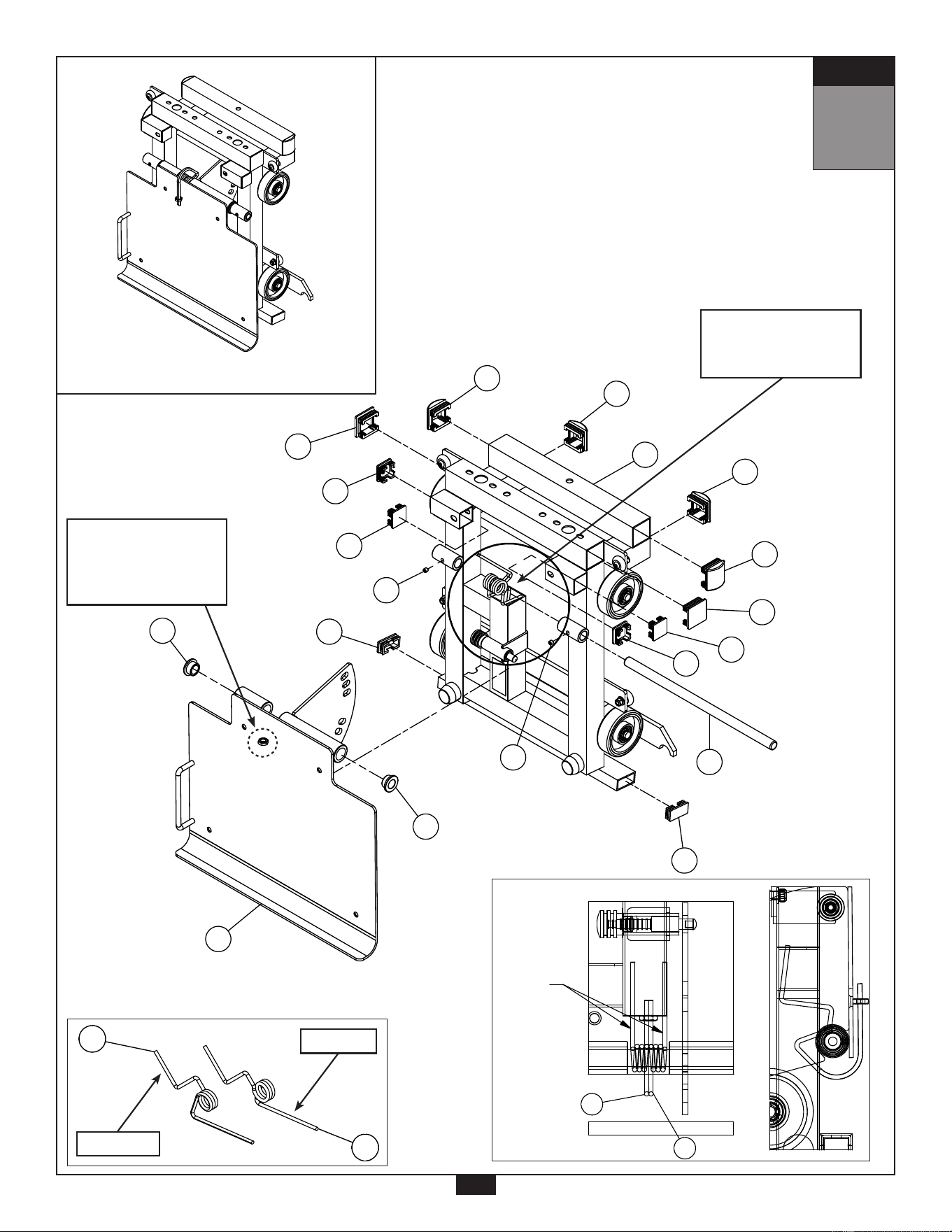
A. Insert two End Caps (39) into Carriage (H).
B. Insert four End Caps (38) into Carriage (H).
C. Insert two End Caps (29) into Carriage (H).
D. Insert four End Caps (30) into Carriage (H).
E. Unscrew both Allen Screws (13) from Carriage (H) to loosen Shaft (48).
F. Slide Shaft (48) out of Carriage (H).
G. Connect Adjustable Plate (K) to Carriage (H) by using:
Two 41 (copper spacer)
One 48 (shaft)
One 45 (torsional spring)
One 46 (torsional spring)
NOTE: Make sure Torsion Springs (45) and (46) are inserted as shown.
H. Tighten both Allen Screws (13) in Carriage (H).
S T E P
Above shows STEP 2
assembled and completed
6
DetailView
45
46
torsional
spring
30
30
29
38
38
39
41
29
38
13
39
48
30
H
30
38
13
41
K
13
S T E P
2
Above shows Step 2 assembled and completed.
S T E P
Above shows STEP 2
assembled and completed
6
DetailView
45
46
torsional
spring
30
30
29
38
38
39
41
29
38
13
39
48
30
H
30
38
13
41
K
S T E P
Above shows STEP 2
assembled and completed
6
DetailView
45
46
torsional
spring
30
30
29
38
38
39
41
29
38
13
39
48
30
H
30
38
13
41
K
Torsion Springs
GLPH-1100 ASSEMBLY INSTRUCTIONS
HARDWARE ILLUSTRATION
28. 45X45 End Cap(9211-091)-------------------------------------------------------
29. 2"X2" End Cap(9211-006)--------------------------------------------------------
30. 2"X2" End Cap(9211-087)--------------------------------------------------------
31. Ø50 Round End Cap(9211-020)------------------------------------------------
32. 2"X2"L Foot Cap(9211-024)------------------------------------------------------
33. Ø20 Round End Cap(9211-036)------------------------------------------------
34. 2"X2" Rubber Dount(9212-010)-------------------------------------------------
35. 38X75L Rubber Pad(9310-002)-------------------------------------------------
36. 38X325L Rubber Pad(9310-042)-----------------------------------------------
37. Ø1"X2.5T Round End Cap(9260-021)-----------------------------------------
38. 38X38 End Cap(9211-003)-------------------------------------------------------
39. 25X50 End Cap(9211-009)-------------------------------------------------------
40. Bearing (8510-002) (pre-installed)----------------------------------------------
41. Copper pulley spacer (8520-013) (pre-installed)----------------------------
42. Convexity loop (9213-018) (pre-installed)-------------------------------------
43. Chrome collar (8890-006) (pre-installed)--------------------------------------
44. Foam Grip (9162-010) (pre-installed)------------------------------------------
45. Torsional spring (8840-044) (pre-installed)-----------------------------------
46. Torsional spring (8840-045) (pre-installed)-----------------------------------
47. Baffle-wall (9310-018) (pre-installed)-------------------------------------------
48. Axis of rotation (8210-044) (pre-installed)-------------------------------------
49. C-clip (pre-installed)----------------------------------------------------------------
50. BodySolid logo (9440-028) (pre-installed)------------------------------------
51. BodySolid plastic plate (9440-199) (pre-installed)--------------------------
52. Pop Pin sticker (9440-104) (pre-installed)-------------------------------------
53. Maintenance label (9440-103) (pre-installed)--------------------------------
54. Warning sticker (9440-105) (pre-installed)------------------------------------
55. General warning sticker (9440-066) (pre-installed)-------------------------
56. Pinch points sticker (9440-220) (pre-installed)-------------------------------
57. Spring warning sticker (9440-217) (pre-installed)---------------------------
58. Safety warning sticker (9440-208) (pre-installed)---------------------------
28
29
30
31
32
33 34
35
36
37
38
39
2
40
42
43
44
45
46
47
48
49
41
[2PCS]
[3PCS]
[4PCS]
[2PCS]
[7PCS]
[8PCS]
[2PCS]
[2PCS]
[1PCS]
[4PCS]
[4PCS]
[2PCS]
[8PCS]
[2PCS]
[4PCS]
[2PCS]
[2PCS]
[1PCS]
[1PCS]
[2PCS]
[1PCS]
[8PCS]
[2PCS]
[1PCS]
[2PCS]
[1PCS]
[1PCS]
[1PCS]
[1PCS]
[1PCS]
[1PCS]
S T E P
Above shows STEP 2
assembled and completed
6
torsional spring
DetailView
30
30
29
38
38
39
45
46
41
K
41
29
38
13
39
48
30
H
30
38
13
S T E P
Above shows STEP 2
assembled and completed
6
torsional spring
DetailView
30
30
29
38
38
39
45
46
41
K
41
29
38
13
39
48
30
H
30
38
13
GLPH-1100 ASSEMBLY INSTRUCTIONS
HARDWARE ILLUSTRATION
28. 45X45 End Cap(9211-091)-------------------------------------------------------
29. 2"X2" End Cap(9211-006)--------------------------------------------------------
30. 2"X2" End Cap(9211-087)--------------------------------------------------------
31. Ø50 Round End Cap(9211-020)------------------------------------------------
32. 2"X2"L Foot Cap(9211-024)------------------------------------------------------
33. Ø20 Round End Cap(9211-036)------------------------------------------------
34. 2"X2" Rubber Dount(9212-010)-------------------------------------------------
35. 38X75L Rubber Pad(9310-002)-------------------------------------------------
36. 38X325L Rubber Pad(9310-042)-----------------------------------------------
37. Ø1"X2.5T Round End Cap(9260-021)-----------------------------------------
38. 38X38 End Cap(9211-003)-------------------------------------------------------
39. 25X50 End Cap(9211-009)-------------------------------------------------------
40. Bearing (8510-002) (pre-installed)----------------------------------------------
41. Copper pulley spacer (8520-013) (pre-installed)----------------------------
42. Convexity loop (9213-018) (pre-installed)-------------------------------------
43. Chrome collar (8890-006) (pre-installed)--------------------------------------
44. Foam Grip (9162-010) (pre-installed)------------------------------------------
45. Torsional spring (8840-044) (pre-installed)-----------------------------------
46. Torsional spring (8840-045) (pre-installed)-----------------------------------
47. Baffle-wall (9310-018) (pre-installed)-------------------------------------------
48. Axis of rotation (8210-044) (pre-installed)-------------------------------------
49. C-clip (pre-installed)----------------------------------------------------------------
50. BodySolid logo (9440-028) (pre-installed)------------------------------------
51. BodySolid plastic plate (9440-199) (pre-installed)--------------------------
52. Pop Pin sticker (9440-104) (pre-installed)-------------------------------------
53. Maintenance label (9440-103) (pre-installed)--------------------------------
54. Warning sticker (9440-105) (pre-installed)------------------------------------
55. General warning sticker (9440-066) (pre-installed)-------------------------
56. Pinch points sticker (9440-220) (pre-installed)-------------------------------
57. Spring warning sticker (9440-217) (pre-installed)---------------------------
58. Safety warning sticker (9440-208) (pre-installed)---------------------------
28
29
30
31
32
33 34
35
36
37
38
39
2
40
42
43
44
45
46
47
48
49
41
[2PCS]
[3PCS]
[4PCS]
[2PCS]
[7PCS]
[8PCS]
[2PCS]
[2PCS]
[1PCS]
[4PCS]
[4PCS]
[2PCS]
[8PCS]
[2PCS]
[4PCS]
[2PCS]
[2PCS]
[1PCS]
[1PCS]
[2PCS]
[1PCS]
[8PCS]
[2PCS]
[1PCS]
[2PCS]
[1PCS]
[1PCS]
[1PCS]
[1PCS]
[1PCS]
[1PCS]
Place the long side of
both Torsion Springs
into the pre-mounted
hole located on the rear
of Adjustable Plate (K).
Place the short side of
both Torsion Springs
into the square tube as
shown.
Long Side
Short Side
Torsion Springs

14
S T E P
3
Be careful to assemble all components
in the sequence they are presented.
NOTE: Two people are required to assemble this section.
Tighten all hardware at the end of this step.
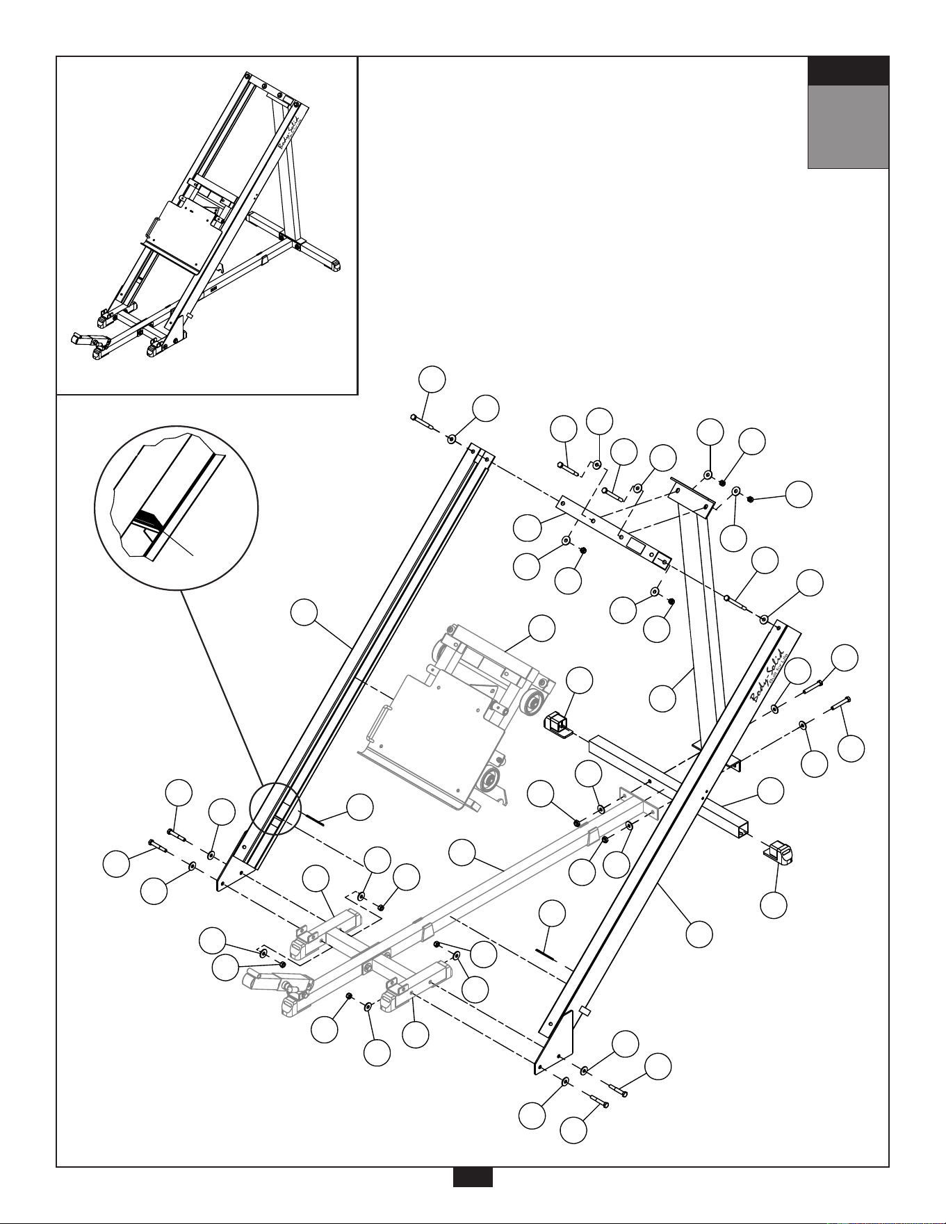
A. Connect Right Glide Frame (F) to Right Stabilizer Frame (C) using:
Two 1 (M12x75 hex head bolt)
Four 22 (M12 washer)
Two 18 (M12 nylon lock nut)
B. Connect Left Glide Frame (G) to Left Stabilizer Frame (D) using:
Two 1 (M12x75 hex head bolt)
Four 22 (M12 washer)
Two 18 (M12 nylon lock nut)
C. Attach Rubber Pads (35) into Left Glide Frame (G) and Right Glide Frame (F).
NOTE: Secure Rubber Pads (35) as shown in the diagram.
D. Slide Carriage (H) into Left Glide Frame (G) and Right Glide Frame (F).
NOTE: Carriage (H) is extremely heavy. Two people are required for this installation.
E. Insert two Foot Caps (32) into Base Cross Bar (E).
F. Connect Upright (B) to Base Cross Bar (E) and Base Frame (A) using:
Two 2 (M12x80 hex head bolt)
Four 22 (M12 washer)
Two 18 (M12 nylon lock nut)
G. Connect Cross Bar (AD) to Upright (B) using:
Two 4 (M12x125 hex head bolt)
Four 22 (M12 washer)
Two 18 (M12 nylon lock nut)
H. Secure Left Glide Frame (G) and Right Glide Frame (F) to Cross Bar (AD) using:
Two 5 (M12x135 hex head bolt)
Four 22 (M12 washer)
Two 18 (M12 nylon lock nut)
S T E P
Above shows STEP 3
assembled and completed
7
22
18
22
18
22
1
1
1
22
22
18
22
22
22
35
5
22
22
18
35
18
1
C
D
22
18
G
F
32
22
22
A
18
18
35
32
B
H
22
18
22
18
AD
4
22
4
22
5
22
E
22
2
22
2
15
S T E P
3
Above shows Step 3 assembled and completed.
S T E P
Above shows STEP 3
assembled and completed
7
22
18
22
18
22
1
1
1
22
22
18
22
22
22
35
5
22
22
18
35
18
1
C
D
22
18
G
F
32
22
22
A
18
18
35
32
B
H
22
18
22
18
AD
4
22
4
22
5
22
E
22
2
22
2
ASSEMBLY INSTRUCTIONS
Page
GLPH-1100
GLPH-1100.2-062008
C2
B1
ASSEMBLY STEP 3
D8
G
F
A5
C2
C2
A5
C2
B1
C2
B1
C2
B1
AD
A1
C2
A1
C2
C2
B1
C2
D8
B1
B1
C2
D8
B1
C2
C2
A1
C2
A1
STEP 2
STEP 1
A4
A4
C2
C2
7
by
by
®
®
by
by
®
®

16
S T E P
4
Be careful to assemble all components
in the sequence they are presented.
NOTE: Tighten all hardware at the end of this step.
A. Connect Foot Plate (S) to Left Stabilizer Frame (D) and Right Stabilizer Frame (C) and secure
using:
Two 3 (M12x90 hex head bolt)
Four 21 (M12x25 washer)
Two 18 (M12 nylon lock nut)
B. Connect Foot Plate (S) to Selector Insert Frame (N) and secure using:
One 3 (M12x90 hex head bolt)
Two 21 (M12x25 washer)
One 18 (M12 nylon lock nut)
C. Insert two Round End Caps (37) into the ends of Right Adjustment Bar (L) and two Round
End Caps (37) to the ends of Left Adjustment Bar (M).
D. Insert four Round End Caps (33) into Right Adjustment Bar (L) and four Round End Caps (33)
into Left Adjustment Bar (M) as shown.
E. Slide the short end of Right Adjustment Bar (L) into the round insert bracket on Right Glide
Frame (F) as shown in the diagram.
NOTE: A detailed view of the long and short Adjustment Bar ends are shown in the figure on
the next page.
F. Insert the long end of Right Adjustment Bar (L) into Slide Tube (P) then secure Slide Tube (P)
onto Right Glide Frame (F) using:
Two 8 (M8x20 hex head bolt)
Four 25 (M8 washer)
Two 20 (M8 nylon lock nut)
G. Slide the short end of Left Adjustment Bar (M) into the round insert bracket on Left Glide Frame
(G).
NOTE: A detailed view of the long and short Adjustment Bar ends are shown in the figure on
the next page.
H. Insert the long end of Left Adjustment Bar (M) into Slide Tube (P) then secure Slide Tube (P)
onto Left Glide Frame (G) using:
Two 8 (M8x20 hex head bolt)
Four 25 (M8 washer)
Two 20 (M8 nylon lock nut)
S T E P
Above shows STEP 4
assembled and completed
8
3
21
21
18
3
21
short
long
long
short
21
18
21
18
21
Round
Insert
Bracket
S
N
M
L
H
8
25
8
25
PX2
25
20
20
25
37X4
33X4
F
3
D
C
33X4
G
Short End
Long End
Round
Insert
Bracket
by
by
®
®
17
S T E P
4
Above shows Step 4 assembled and completed.
S T E P
Above shows STEP 4
assembled and completed
8
3
21
21
18
3
21
short
long
long
short
21
18
21
18
21
Round
Insert
Bracket
S
N
M
L
H
8
25
8
25
PX2
25
20
20
25
37X4
33X4
F
3
D
C
33X4
G
S T E P
Above shows STEP 4
assembled and completed
8
S
L
M
A8X4
C5X8
B3X4
PX2
D10X4
D6X4
A3
A3
C1
C1
B1
A3
C1
short
long
G
F
long
short
D
N
C1
B1
C1
B1
C
C1
Short End
Long End
by
by
®
®
Adjustment Bar Diagram

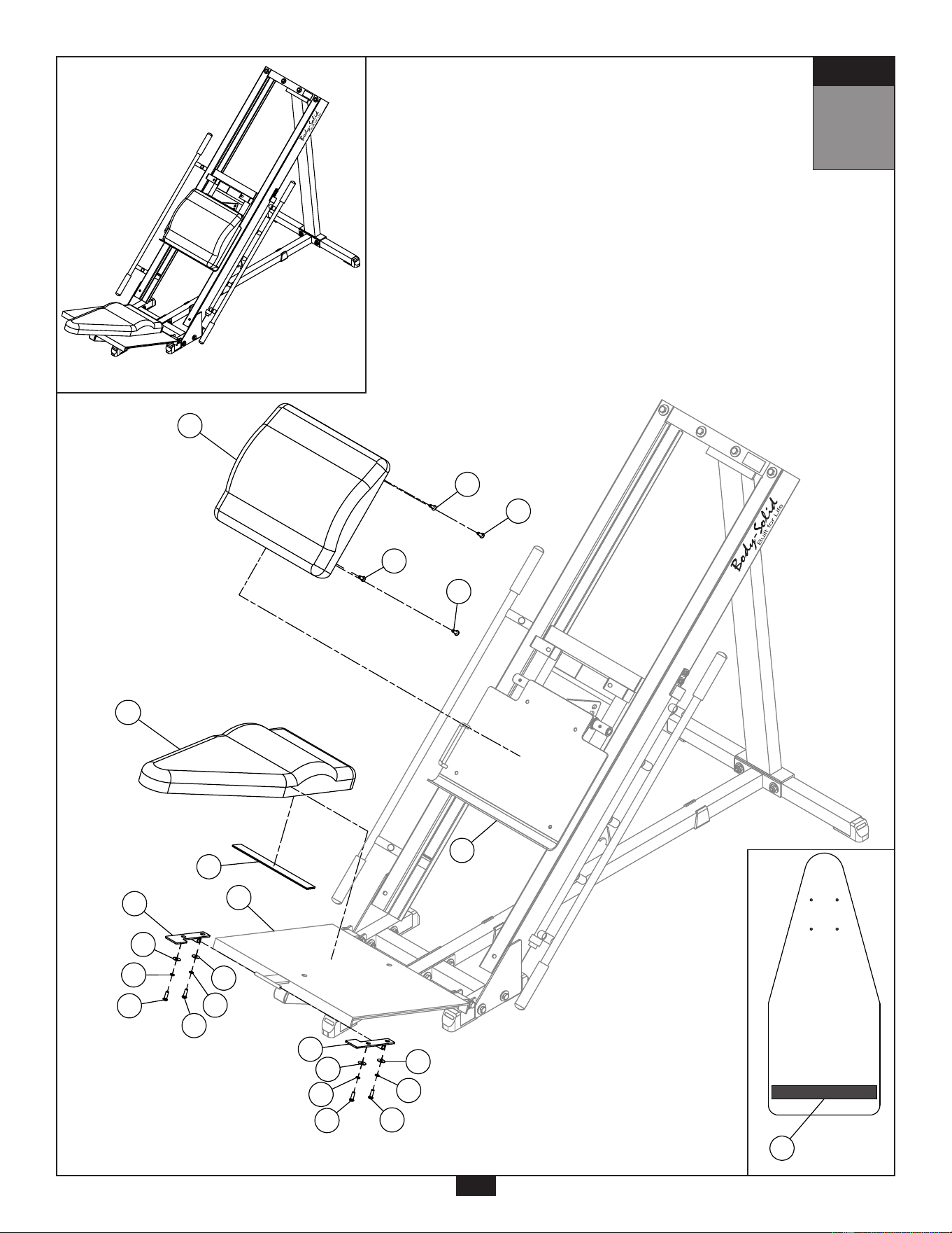
18
S T E P
5
Be careful to assemble all components
in the sequence they are presented.
NOTE: Tighten all hardware at the end of this step.
A. Connect Upper Pad (Y) to Adjustable Plate (K) using:
Four 9 (5/16” x 1” allen pan head bolt)
NOTE: Do not over tighten Pad Bolts (9), over tightening will strip the T-nuts pressed into
the wood.
B. Attach Rubber Pad (36) to Lower Pad (AA).
NOTE: See figure on next page for a detailed view.
C. Slide Left Lower Mount Frame (T) and Right Lower Mount Frame (U) onto the rod on Foot Plate (S)
and secure Left Lower Mount Frame (T) and Right Lower Mount Frame (U) onto Lower Pad (AA)
using:
Four 10 (5/16” x 1” round allen head bolt)
Four 26 (M8 spring washer)
Four 25 (M8 washer)
NOTE: Do not over tighten Pad Bolts (10), over tightening will strip the T-nuts pressed into
the wood.
19
S T E P
5
S T E P
Above shows STEP 5
assembled and completed
9
Y
25
26
10
36
AA
T
36
S
25
26
10
25
26
10
U
25
26
10
K
9
9
9
9
Above shows Step 5 assembled and completed.
S T E P
Above shows STEP 5
assembled and completed
9
Y
25
26
10
36
AA
T
36
S
25
26
10
25
26
10
U
25
26
10
K
9
9
9
9
S T E P
Above shows STEP 5
assembled and completed
9
Y
25
26
10
36
AA
T
36
S
25
26
10
25
26
10
U
25
26
10
K
9
9
9
9
Lower Pad
Underside
by
by
®
®
by
by
®
®

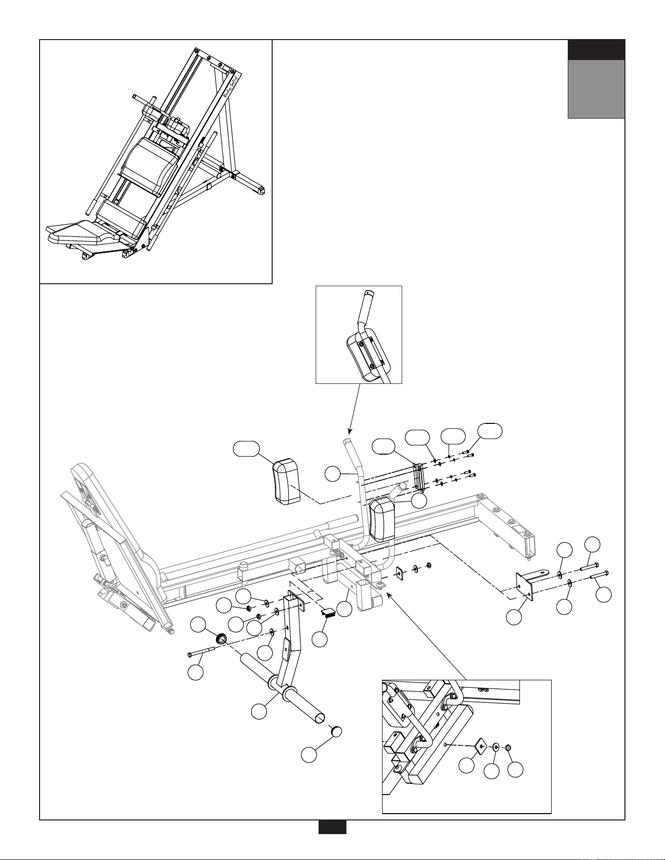
20
S T E P
6
Be careful to assemble all components
in the sequence they are presented.
NOTE: Tighten all hardware at the end of this step.
A. Connect Middle Pad (AC) to Right Glide Frame (F) and Left Glide Frame (G) using:
Two 11 (5/16” x 1 ¼” hex head bolt)
Two 26 (M8 spring washer)
Two 25 (M8 washer)
NOTE: See correct installation direction in diagram.
Do not over tighten Pad Bolts (11), over tightening will strip the T-nuts pressed into
the wood.
B. Connect Left Arm (Q) to Carriage (H) and secure using:
Two 7 (M10x75 hex head bolt)
Five 24 (M10 washer)
Two 19 (M10 nylon lock nut)
One 6 (M10x20) hex head bolt
C. Connect Right Arm (R) to Carriage (H) and secure using:
Two 7 (M10x75 hex head bolt)
Five 24 (M10 washer)
Two 19 (M10 nylon lock nut)
One 6 (M10x20) hex head bolt
21
S T E P
6
Above shows Step 6 assembled and completed.
S T E P
Above shows STEP 6
assembled and completed
10
R
Q
C4X2
A7X2
C4X2
A7X2
C5X2
C6X2
A11X2
B2X2
A6X2
B2X2
C4X2
C4X2
C4X2
AC
l
o
n
g
sh
o
r
t
direction to install
F
Detail View
Detail View
G
S T E P
Above shows STEP 6
assembled and completed
10
24X2
19X2
24X2
24X2
l
o
n
g
sh
o
r
t
direction to install
Detail View
Detail View
G
AC
25
26
11
25
26
11
F
19X2
6X2
24X2
24X2
7X2
7X2
Q
R
H
by
by
®
®
S T E P
Above shows STEP 6
assembled and completed
10
R
Q
C4X2
A7X2
C4X2
A7X2
C5X2
C6X2
A11X2
B2X2
A6X2
B2X2
C4X2
C4X2
C4X2
AC
l
o
n
g
sh
o
r
t
direction to install
F
Detail View
Detail View
G
S T E P
Above shows STEP 6
assembled and completed
10
R
Q
C4X2
A7X2
C4X2
A7X2
C5X2
C6X2
A11X2
B2X2
A6X2
B2X2
C4X2
C4X2
C4X2
AC
l
o
n
g
sh
o
r
t
direction to install
F
Detail View
Detail View
G
S T E P
Above shows STEP 6
assembled and completed
10
24X2
19X2
24X2
24X2
l
o
n
g
sh
o
r
t
direction to install
Detail View
Detail View
G
AC
25
26
11
25
26
11
F
19X2
6X2
24X2
24X2
7X2
7X2
Q
R
H
by
by
®
®
Pad
Direction

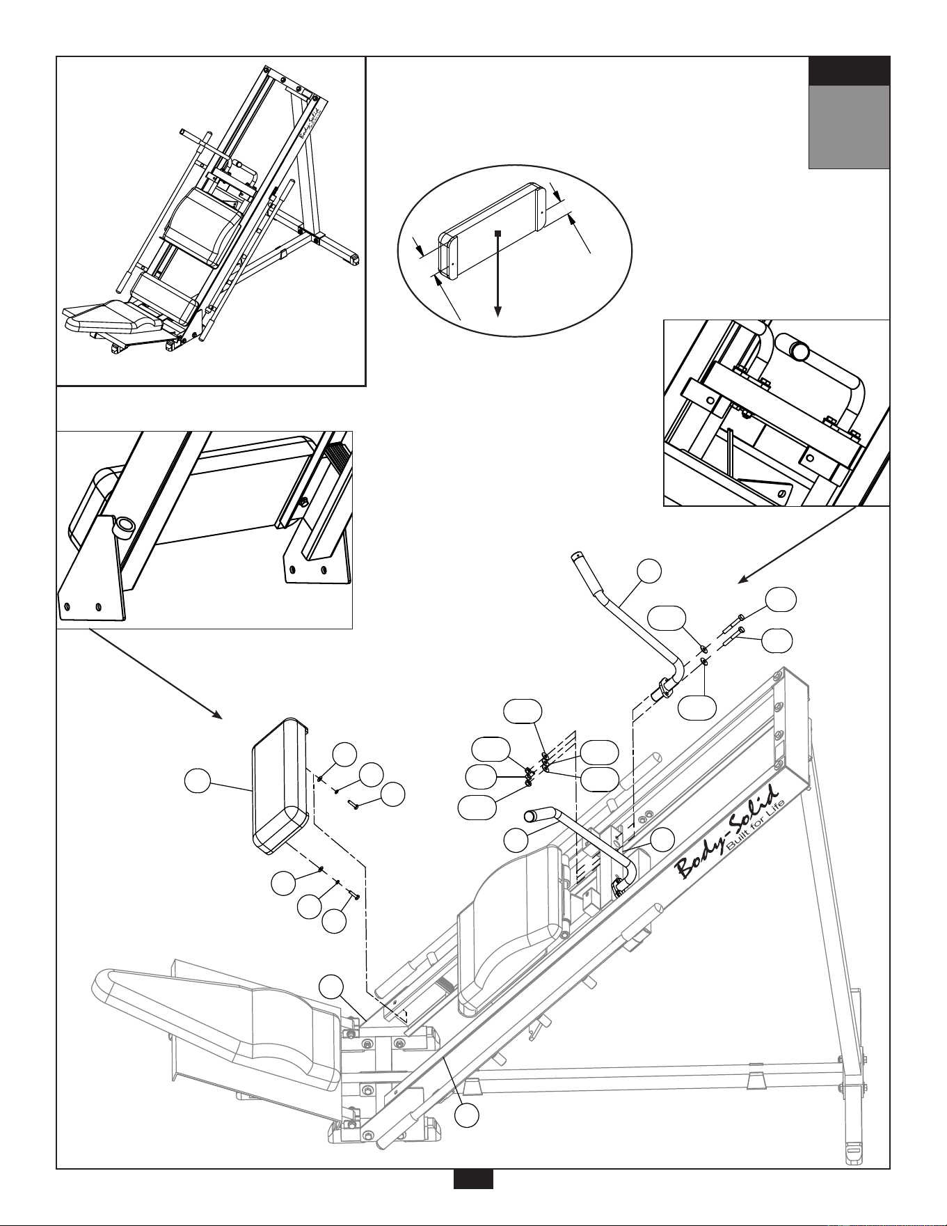
22
S T E P
7
Be careful to assemble all components
in the sequence they are presented.
NOTE: Tighten all hardware at the end of this step.
A. Insert End Cap (29) into Weight Horn Bar (J).
B. Insert two Round End Caps (31) into Weight Horn Bar (J).
C. Connect Weight Horn Bar (J) and Weight Horn Bar Support Plate (X) to Carriage (H) using:
Two 2 (M12x80 hex head bolt)
Four 22 (M12 washer)
Two 18 (M12 nylon lock nut)
D. Secure Weight Horn Bar (J) to Carriage (H) by adding:
One 4 (M12x125 hex head bolt)
Two 22 (M12 washer)
One V (Support Plate)
One 18 (M12 nylon lock nut)
E. Connect Arm Pad (AB) and Pad Frame (W) to Left Arm (Q) using:
Four 10 (5/16” x 1” round allen head bolt)
Four 26 (M8 spring washer)
Four 27 (M8 washer)
NOTE: Do not over tighten Pad Bolts (10), over tightening will strip the T-nuts pressed into
the wood.
F. Connect Arm Pad (AB) and Pad Frame (W) to Right Arm (R) using:
Four 10 (5/16” x 1” round allen head bolt)
Four 26 (M8 spring washer)
Four 27 (M8 washer)
NOTE: Do not over tighten Pad Bolts (10), over tightening will strip the T-nuts pressed into
the wood.
S T E P
Above shows STEP 7
assembled and completed
Detail View
11
WX2
31
H
ABX2
22
18
18
22
31
4
J
22
29
V
22
18
22
2
22
2
R
Q
27X8
26X8
10X8
X
23
S T E P
7
Above shows Step 7 assembled and completed.
S T E P
Above shows STEP 7
assembled and completed
Detail View
11
WX2
31
H
ABX2
22
18
18
22
31
4
J
22
29
V
22
18
22
2
22
2
R
Q
27X8
26X8
10X8
X
by
by
®
®

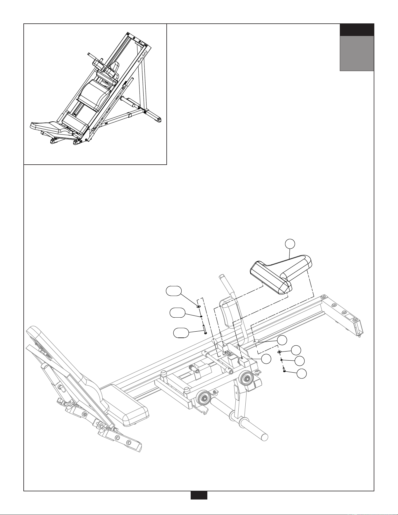
24
S T E P
8
Be careful to assemble all components
in the sequence they are presented.
NOTE: Tighten all hardware at the end of this step.
A. Connect Head Rest Pad (Z) to Carriage (H) using:
Two 12 (5/16” x 2 ¼” hex head bolt)
Two 26 (M8 spring washer)
Two 25 (M8 washer)
NOTE: Do not over tighten Pad Bolts (12), over tightening will strip the T-nuts pressed into
the wood.
B. Connect Head Rest Pad (Z) to Weight Horn Bar Support Plate (X) using:
One 10 (5/16” x 1” round allen head bolt)
One 26 (M8 spring washer)
One 25 (M8 washer)
NOTE: Do not over tighten Pad Bolt (10), over tightening will strip the T-nut pressed into
the wood.
C. Congratulations!! The assembly of your GLPH1100 is now complete.
25
S T E P
8
Above shows Step 8 assembled and completed.
S T E P
Above shows STEP 8
assembled and completed
12
25X2
26X2
12X2
Z
X
H
25
26
10
S T E P
Above shows STEP 8
assembled and completed
12
25X2
26X2
12X2
Z
X
H
25
26
10
by
by
®
®

W a r n i n g , S a f e t y & M a i n t e n a n c e
26
Precision craftsmanship assures Body-Solid’s ability to
consistently deliver products of the highest standards.
Our products have been carefully designed to ensure
safe, efficient long term operation.
However, it must be realized that safe use of this
equipment requires that owners carefully read and follow
the Body-Solid use recommendations, warnings, and
maintenance guidelines in this Owners Manual.
Routine inspection and maintenance is of critical
importance to ensure maximum safety and performance.
Body-Solid uses the highest quality materials available,
but wear is inevitable. Therefore, you must carefully
inspect your equipment as outlined in the Maintenance
Schedule.
Be advised that dangerous conditions can arise even
during a warranty period. A warranty does not negate the
owner’s responsibility to thoroughly, carefully and daily
inspect the machine.
Including maintaining the equipment, the owner’s
responsibility is also to:
m Be sure to always provide adequate supervision to
all end-users.
m Be sure to instruct all end-users of proper usage.
m Be sure all supervisors and personal trainers who
instruct end-users on equipment use are properly
trained and know the function and importance of
every adjustment and setting.
Also, be sure these trainers provide proper
instruction to end-users on the fundamentals of
strength training.
UPHOLSTERY:
m Wipe down after every workout.
m Periodically take the time to use a mild soap or a
mild vinyl upholstery cleaner. Avoid using any
abrasive cleaner not intended for use on vinyl.
m Keep sharp or pointed objects out of your pockets
and clear of all upholstery.
NUTS/BOLTS/FASTENERS:
m Periodically inspect all nuts and bolts. Tighten if
needed. If bolts seem to loosen periodically, use
Loctite 242 for a long-term cure.
m Go through a re-tightening sequence periodically to
ensure that all hardware is properly tensioned.
ADJUSTMENTS / LOCKING PINS /
TIGHTENING KNOBS:
m Check all pieces for signs of visible wear or damage.
m Check springs in Snap Links and Pop Pins for proper
tension and alignment.
m If the spring sticks or has lost its rigidity, replace it
immediately.
ANTI-SKID SURFACES:
m Replace if they appear worn or become slippery.
WARNING INSTRUCTION LABELS:
m Inspect and familiarize yourself with all safety
warnings and other user information on decals.
G L P H 1 1 0 0
T o r s i o n S p r i n g R e m o v a l
Remove the two Set Screws
(13).
•
Remove the M12x135 Hex
Head Bolt (5) as shown.
or if Shaft (48) is not
threaded as shown in
the gure,
skip this step
.
•
Thread the M12x135 Hex
Head Bolt (5) onto Shaft (48)
and leave it nger tight.
or if Shaft (48) is not
threaded, then use a
punch or other tool that
can be used to push out
Shaft (48).
•
48

G L P H 1 1 0 0
T o r s i o n S p r i n g R e m o v a l
Use a hammer to tap on the
head of the threaded bolt or
punch.
•
Continue using a hammer
until the bolt or punch ter-
minates near the axis open-
ing or Shaft (48) is protrud-
ing out of the opposite end.
•
Unscrew and remove the
bolt, if this method has been
used.
Remember to reinstall
the bolt back onto the
GLPH1100 mainframe.
•
•
49

G L P H 1 1 0 0
T o r s i o n S p r i n g R e m o v a l
Remove Shaft (48) by rotat-
ing and pulling it out of the
axis of rotation.
Lubrication may be required
for this procedure.
•
•
Carefully lift Adjustable
Plate (K) away from the
GLPH1100.
•
Remove both Torsion
Springs (45) & (46).
•
50

G L P H 1 1 0 0
T o r s i o n S p r i n g I n s t a l l a t i o n
Insert the long side of Tor-
sion Springs (45) & (46) into
the rear hole of Adjustable
Plate (K).
•
Insert the short side of the
Torsion Springs (45) & (46)
into the square frame on
Carriage (H) as shown.
•
Insert Shaft (48) into the
rst section of the axis.
Lubrication may assist with
this procedure.
•
•
51

G L P H 1 1 0 0
T o r s i o n S p r i n g I n s t a l l a t i o n
Push Shaft (48) inward mak-
ing sure that both axis are
alligned.
•
Torsion Springs (45) & (46)
will need slight alignment
while Shaft (48) is being in-
serted.
•
Use a hammer to aid the
process.
•
52

G L P H 1 1 0 0
T o r s i o n S p r i n g I n s t a l l a t i o n
Once the shaft passes the
rst Torsion Spring, tap on
the second Torsion Spring to
bring it into alignment with
the axis of rotation.
•
Use a hammer to continue
inserting Shaft (48).
•
Make sure the remainder
of Carriage (H) is aligned
and continue to insert Shaft
(48).
Upon completion, tighten
the two Set Screws (13) to
secure Shaft (48).
•
•
53

54
M a i n f r a m e P a r t s L i s t
Part# Qty Description
A 1 BASE FRAME
B 1 UPRIGHT
C 1 RIGHT STABILIZER FRAME
D 1 LEFT STABILIZER FRAME
E 1 BASE CROSS BAR
F 1 RIGHT GLIDE FRAME
G 1 LEFT GLIDE FRAME
H 1 CARRIAGE
J 1 WEIGHT HORN BAR
K 1 ADJUSTABLE PLATE
L 1 RIGHT ADJUST BAR
M 1 LEFT ADJUST BAR
N 1 SELECTOR INSERT FRAME
O 1 SELECTOR TUBE
P 2 SLIDE TUBE
Q 1 LEFT ARM
R 1 RIGHT ARM
S 1 FOOT PLATE
T 1 LEFT LOWER MOUNT FRAME
U 1 RIGHT LOWER MOUNT FRAME
V 1 SUPPORT PLATE (8312-013)
W 2 PAD FRAME (8343-023)
X 1 WEIGHT HORN BAR SUPPORT PLATE (8333-045)
Y 1 UPPER PAD (9112-026)
Z 1 HEAD REST PAD (9132-016)
AA 1 LOWER PAD (9112-025)
AB 2 ARM PAD (9132-002)
AC 1 MIDDLE PAD (9122-031)
AD 1 CROSS BAR
Part numbers are required when ordering parts.
Part# Qty Description

55
H a r d w a r e L i s t
( c o n t i n u e d )
Part numbers are required when ordering parts.
1 4 HEX HEAD BOLT M12x75
2 6 HEX HEAD BOLT M12x80
3 4 HEX HEAD BOLT M12x90
4 3 HEX HEAD BOLT M12x125
5 2 HEX HEAD BOLT M12x135
6 2 HEX HEAD BOLT M10x20
7 4 HEX HEAD BOLT M10x75
8 4 HEX HEAD BOLT M8x20
9 4 ALLEN PAN HEAD BOLT 5/16” x 1”
10 13 ROUND ALLEN HEAD BOLT 5/16” x 1”
11 2 HEX HEAD BOLT 5/16” x 1 ¼”
12 2 HEX HEAD BOLT 5/16” x 2 ¼”
13 2 ALLEN SCREW M8X8 - PREINSTALLED
14 4 ROUND ALLEN HEAD BOLT M8x30 - PREINSTALLED
15 4 ALLEN SCREW M5x5 - PREINSTALLED
16 1 POP PIN M31.5x115L (8250-033) - PREINSTALLED
17 1 POP PIN M22x78L (8250-033) - PREINSTALLED
18 19 NYLON LOCK NUT M12
19 4 NYLON LOCK NUT M10
20 8 NYLON LOCK NUT M8
21 8 WASHER M12 ID 25MM OD
22 30 WASHER M12 ID 34MM OD
24 10 WASHER M10 ID 27MM OD
25 17 WASHER M8 ID 24MM OD
26 21 SPRING WASHER M8
27 12 WASHER M8 ID 18MM OD
28 2 END CAP M45x45 (9211-091)
29 3 END CAP 2” x 2” (9211-006)
30 4 END CAP 2” x 2” (9211-087)
31 2 ROUND END CAP Ø50 (9211-020)
32 7 FOOT CAP 2” x 2” (9211-024)
33 8 ROUND END CAP Ø20 (9211-036)
34 2 BASE CAP 2” x 2” (9212-010)
35 2 RUBBER PAD M38x75 (9310-002)
36 1 RUBBER PAD M38x325 (9310-042)
37 4 ROUND END CAP 1” x 2.5T (9260-021)
38 4 END CAP M38x38 (9211-003)
39 2 END CAP M25x50 (9211-009)
40 8 BEARING (8510-002) - PREINSTALLED
41 2 COPPER SPACER (8520-013)
42 4 CONVEXITY LOOP (9213-018) - PREINSTALLED
43 2 CHROME COLLAR Ø35xØ26X19L (8890-061) - PREINSTALLED
44 2 FOAM GRIP (9162-010) - PREINSTALLED
45 1 TORSION SPRING (8840-044) - PREINSTALLED
46 1 TORSION SPRING (8840-045) - PREINSTALLED
47 2 BAFFLE WALL (9310-018) - PREINSTALLED
48 1 SHAFT ؾ” x 410L (8210-044) - PREINSTALLED
49 8 C-CLIP
50 2 BODY SOLID LOGO (9440-028) - PREINSTALLED
51 1 BODY SOLID PLATE (9440-199) - PREINSTALLED
52 2 POP PIN STICKER (9440-104) - PREINSTALLED
53 1 MAINTENANCE LABEL (9440-103) - PREINSTALLED
54 1 GENERAL WARNING STICKER (9440-217) - PREINSTALLED
55 1 SELECTOR STICKER (9440-066) - PREINSTALLED
56 1 CAUTION STICKER (9440-220) - PREINSTALLED
57 1 WEIGHT HORN WARNING STICKER (9440-217) - PREINSTALLED
58 1 PLATE DANGER STICKER (9440-208) - PREINSTALLED
59 4 FOAM GRIP (9162-002) - PREINSTALLED
60 4 PU WHEEL (9213-044) - PREINSTALLED
Part# Qty Description
45
56
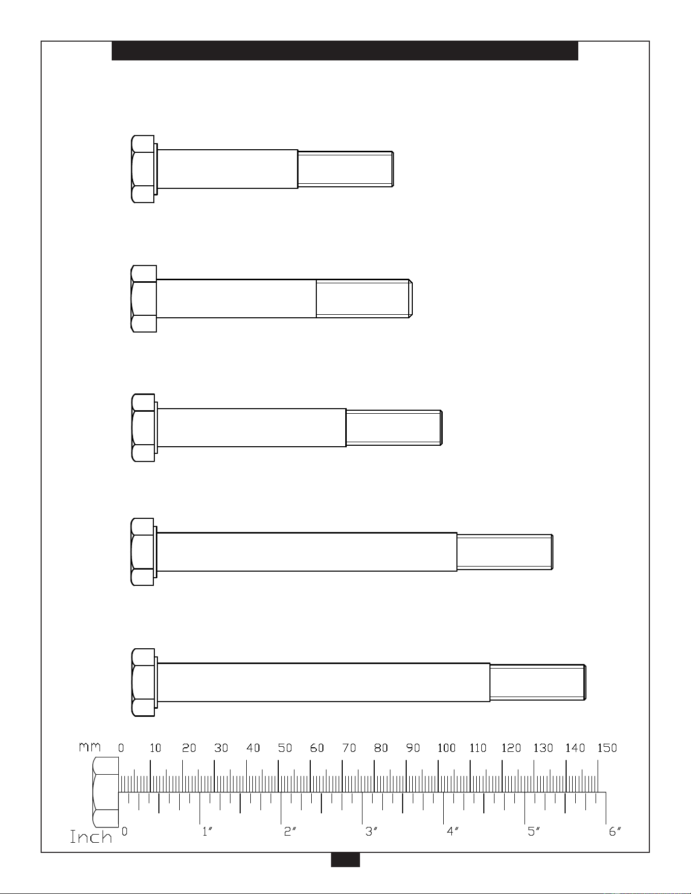
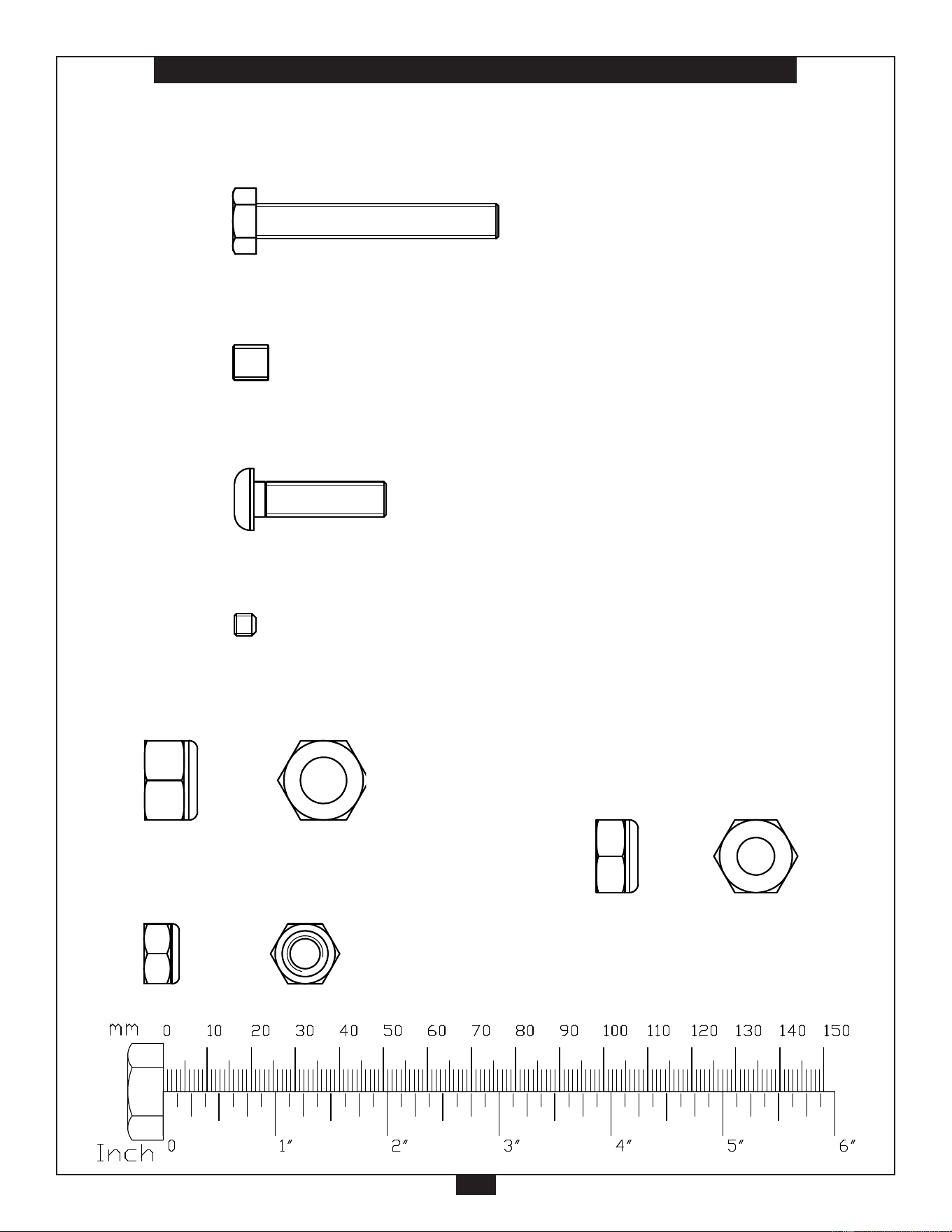
H a r d w a r e
( T o S c a l e )
Part# 1 M12x75 Hex Head Bolt (Partial Thread) Qty. 4
G L P H - 1 1 0 0 H A R D W A R E
( s h o w n i n a c t u a l s i z e )
KEY #A1 HEX HEAD BOLT M12 X 75 PARTIAL THREAD QTY.4
KEY #A2 HEX HEAD BOLT M12 X 80 PARTIAL THREAD QTY.6
KEY #A3 HEX HEAD BOLT M12 X 90 PARTIAL THREAD QTY.4
KEY #A5 HEX HEAD BOLT M12 X 135 PARTIAL THREAD QTY.2
KEY #A4 HEX HEAD BOLT M12 X 125 PARTIAL THREAD QTY.3
KEY #A6 HEX HEAD BOLT M10 X 20 PARTIAL THREAD QTY.2
1a
Part# 2 M12x80 Hex Head Bolt (Partial Thread) Qty. 6
G L P H - 1 1 0 0 H A R D W A R E
( s h o w n i n a c t u a l s i z e )
KEY #A1 HEX HEAD BOLT M12 X 75 PARTIAL THREAD QTY.4
KEY #A2 HEX HEAD BOLT M12 X 80 PARTIAL THREAD QTY.6
KEY #A3 HEX HEAD BOLT M12 X 90 PARTIAL THREAD QTY.4
KEY #A5 HEX HEAD BOLT M12 X 135 PARTIAL THREAD QTY.2
KEY #A4 HEX HEAD BOLT M12 X 125 PARTIAL THREAD QTY.3
KEY #A6 HEX HEAD BOLT M10 X 20 PARTIAL THREAD QTY.2
1a
Part# 3 M12x90 Hex Head Bolt (Partial Thread) Qty. 4
G L P H - 1 1 0 0 H A R D W A R E
( s h o w n i n a c t u a l s i z e )
KEY #A1 HEX HEAD BOLT M12 X 75 PARTIAL THREAD QTY.4
KEY #A2 HEX HEAD BOLT M12 X 80 PARTIAL THREAD QTY.6
KEY #A3 HEX HEAD BOLT M12 X 90 PARTIAL THREAD QTY.4
KEY #A5 HEX HEAD BOLT M12 X 135 PARTIAL THREAD QTY.2
KEY #A4 HEX HEAD BOLT M12 X 125 PARTIAL THREAD QTY.3
KEY #A6 HEX HEAD BOLT M10 X 20 PARTIAL THREAD QTY.2
1a
Part# 4 M12x125 Hex Head Bolt (Partial Thread) Qty. 3
G L P H - 1 1 0 0 H A R D W A R E
( s h o w n i n a c t u a l s i z e )
KEY #A1 HEX HEAD BOLT M12 X 75 PARTIAL THREAD QTY.4
KEY #A2 HEX HEAD BOLT M12 X 80 PARTIAL THREAD QTY.6
KEY #A3 HEX HEAD BOLT M12 X 90 PARTIAL THREAD QTY.4
KEY #A5 HEX HEAD BOLT M12 X 135 PARTIAL THREAD QTY.2
KEY #A4 HEX HEAD BOLT M12 X 125 PARTIAL THREAD QTY.3
KEY #A6 HEX HEAD BOLT M10 X 20 PARTIAL THREAD QTY.2
1a
Part# 5 M12x135 Hex Head Bolt (Partial Thread) Qty. 2
G L P H - 1 1 0 0 H A R D W A R E
( s h o w n i n a c t u a l s i z e )
KEY #A1 HEX HEAD BOLT M12 X 75 PARTIAL THREAD QTY.4
KEY #A2 HEX HEAD BOLT M12 X 80 PARTIAL THREAD QTY.6
KEY #A3 HEX HEAD BOLT M12 X 90 PARTIAL THREAD QTY.4
KEY #A5 HEX HEAD BOLT M12 X 135 PARTIAL THREAD QTY.2
KEY #A4 HEX HEAD BOLT M12 X 125 PARTIAL THREAD QTY.3
KEY #A6 HEX HEAD BOLT M10 X 20 PARTIAL THREAD QTY.2
1a
45
57
H a r d w a r e
( T o S c a l e )
Part# 6 M10x20 Hex Head Bolt (Partial Thread) Qty. 2
G L P H - 1 1 0 0 H A R D W A R E
( s h o w n i n a c t u a l s i z e )
KEY #A1 HEX HEAD BOLT M12 X 75 PARTIAL THREAD QTY.4
KEY #A2 HEX HEAD BOLT M12 X 80 PARTIAL THREAD QTY.6
KEY #A3 HEX HEAD BOLT M12 X 90 PARTIAL THREAD QTY.4
KEY #A5 HEX HEAD BOLT M12 X 135 PARTIAL THREAD QTY.2
KEY #A4 HEX HEAD BOLT M12 X 125 PARTIAL THREAD QTY.3
KEY #A6 HEX HEAD BOLT M10 X 20 PARTIAL THREAD QTY.2
1a
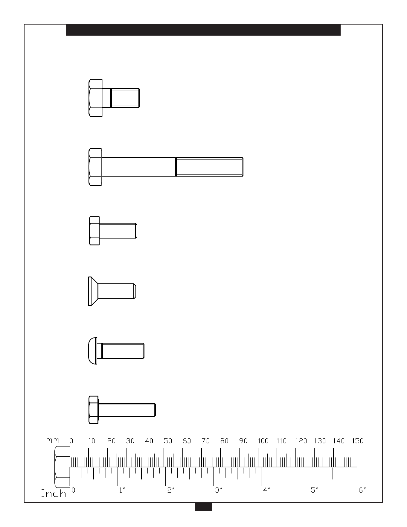
Part# 7 M10x75 Hex Head Bolt (Partial Thread) Qty. 4
KEY #A7 HEX HEAD BOLT M10 X 75 PARTIAL THREAD QTY.4
KEY #A8 HEX HEAD BOLT M8 X 20 FULL THREAD QTY.4
KEY #A9 Co.Noid Head Bolt 5/16" X 1" FULL THREAD QTY.4
KEY #A10 ROUND BOLT 5/16" X 1" PARTIAL THREAD QTY.13
KEY #A11 HEX HEAD BOLT 5/16"X1 1/4" FULL THREAD QTY.2
G L P H - 1 1 0 0 H A R D W A R E
( s h o w n i n a c t u a l s i z e )
KEY #A12 HEX HEAD BOLT 5/16"X2 1/4" FULL THREAD QTY.2
KEY #A13 ALLEN SCREW M8 X 8 FULL THREAD QTY.2 (pre-installed)
1b
Part# 8 M8x20 Hex Head Bolt (Full Thread) Qty. 4
KEY #A7 HEX HEAD BOLT M10 X 75 PARTIAL THREAD QTY.4
KEY #A8 HEX HEAD BOLT M8 X 20 FULL THREAD QTY.4
KEY #A9 Co.Noid Head Bolt 5/16" X 1" FULL THREAD QTY.4
KEY #A10 ROUND BOLT 5/16" X 1" PARTIAL THREAD QTY.13
KEY #A11 HEX HEAD BOLT 5/16"X1 1/4" FULL THREAD QTY.2
G L P H - 1 1 0 0 H A R D W A R E
( s h o w n i n a c t u a l s i z e )
KEY #A12 HEX HEAD BOLT 5/16"X2 1/4" FULL THREAD QTY.2
KEY #A13 ALLEN SCREW M8 X 8 FULL THREAD QTY.2 (pre-installed)
1b
Part# 9 5/16” x 1” Pan Head Bolt (Full Thread) Qty. 4
KEY #A7 HEX HEAD BOLT M10 X 75 PARTIAL THREAD QTY.4
KEY #A8 HEX HEAD BOLT M8 X 20 FULL THREAD QTY.4
KEY #A9 Co.Noid Head Bolt 5/16" X 1" FULL THREAD QTY.4
KEY #A10 ROUND BOLT 5/16" X 1" PARTIAL THREAD QTY.13
KEY #A11 HEX HEAD BOLT 5/16"X1 1/4" FULL THREAD QTY.2
G L P H - 1 1 0 0 H A R D W A R E
( s h o w n i n a c t u a l s i z e )
KEY #A12 HEX HEAD BOLT 5/16"X2 1/4" FULL THREAD QTY.2
KEY #A13 ALLEN SCREW M8 X 8 FULL THREAD QTY.2 (pre-installed)
1b
Part# 10 5/16” x 1”
Round Allen Head Bolt (Partial Thread)
Qty. 13
KEY #A7 HEX HEAD BOLT M10 X 75 PARTIAL THREAD QTY.4
KEY #A8 HEX HEAD BOLT M8 X 20 FULL THREAD QTY.4
KEY #A9 Co.Noid Head Bolt 5/16" X 1" FULL THREAD QTY.4
KEY #A10 ROUND BOLT 5/16" X 1" PARTIAL THREAD QTY.13
KEY #A11 HEX HEAD BOLT 5/16"X1 1/4" FULL THREAD QTY.2
G L P H - 1 1 0 0 H A R D W A R E
( s h o w n i n a c t u a l s i z e )
KEY #A12 HEX HEAD BOLT 5/16"X2 1/4" FULL THREAD QTY.2
KEY #A13 ALLEN SCREW M8 X 8 FULL THREAD QTY.2 (pre-installed)
1b
Part# 11 5/16” x 1 ¼” Hex Head Bolt (Full Thread) Qty. 2
KEY #A7 HEX HEAD BOLT M10 X 75 PARTIAL THREAD QTY.4
KEY #A8 HEX HEAD BOLT M8 X 20 FULL THREAD QTY.4
KEY #A9 Co.Noid Head Bolt 5/16" X 1" FULL THREAD QTY.4
KEY #A10 ROUND BOLT 5/16" X 1" PARTIAL THREAD QTY.13
KEY #A11 HEX HEAD BOLT 5/16"X1 1/4" FULL THREAD QTY.2
G L P H - 1 1 0 0 H A R D W A R E
( s h o w n i n a c t u a l s i z e )
KEY #A12 HEX HEAD BOLT 5/16"X2 1/4" FULL THREAD QTY.2
KEY #A13 ALLEN SCREW M8 X 8 FULL THREAD QTY.2 (pre-installed)
1b
45
58
H a r d w a r e
( T o S c a l e )
Part# 15 M5x5 Allen Screw (Full Thread) Qty. 4
G L P H - 1 1 0 0 H A R D W A R E
( s h o w n i n a c t u a l s i z e )
KEY #A14 ROUND BOLT M8 X 30 PARTIAL THREAD QTY.4 (pre-installed)
KEY #A15 ALLEN SCREW M5 X 5 FULL THREAD QTY.4 (pre-installed)
KEY #A16 POP PIN 31.5x115L (8250-033) QTY.1 (pre-installed)
KEY #A17 POP PIN 22x78L (8250-012) QTY.1 (pre-installed)
1c
Part# 13 M8x8 Allen Screw (Full Thread) Qty. 2
KEY #A7 HEX HEAD BOLT M10 X 75 PARTIAL THREAD QTY.4
KEY #A8 HEX HEAD BOLT M8 X 20 FULL THREAD QTY.4
KEY #A9 Co.Noid Head Bolt 5/16" X 1" FULL THREAD QTY.4
KEY #A10 ROUND BOLT 5/16" X 1" PARTIAL THREAD QTY.13
KEY #A11 HEX HEAD BOLT 5/16"X1 1/4" FULL THREAD QTY.2
G L P H - 1 1 0 0 H A R D W A R E
( s h o w n i n a c t u a l s i z e )
KEY #A12 HEX HEAD BOLT 5/16"X2 1/4" FULL THREAD QTY.2
KEY #A13 ALLEN SCREW M8 X 8 FULL THREAD QTY.2 (pre-installed)
1b
Part# 14 M8x30
Round Allen Head Bolt (Partial Thread)
Qty. 4
G L P H - 1 1 0 0 H A R D W A R E
( s h o w n i n a c t u a l s i z e )
KEY #A14 ROUND BOLT M8 X 30 PARTIAL THREAD QTY.4 (pre-installed)
KEY #A15 ALLEN SCREW M5 X 5 FULL THREAD QTY.4 (pre-installed)
KEY #A16 POP PIN 31.5x115L (8250-033) QTY.1 (pre-installed)
KEY #A17 POP PIN 22x78L (8250-012) QTY.1 (pre-installed)
1c
Part# 12 5/16” x 2 ¼” Hex Head Bolt (Full Thread) Qty. 2
KEY #A7 HEX HEAD BOLT M10 X 75 PARTIAL THREAD QTY.4
KEY #A8 HEX HEAD BOLT M8 X 20 FULL THREAD QTY.4
KEY #A9 Co.Noid Head Bolt 5/16" X 1" FULL THREAD QTY.4
KEY #A10 ROUND BOLT 5/16" X 1" PARTIAL THREAD QTY.13
KEY #A11 HEX HEAD BOLT 5/16"X1 1/4" FULL THREAD QTY.2
G L P H - 1 1 0 0 H A R D W A R E
( s h o w n i n a c t u a l s i z e )
KEY #A12 HEX HEAD BOLT 5/16"X2 1/4" FULL THREAD QTY.2
KEY #A13 ALLEN SCREW M8 X 8 FULL THREAD QTY.2 (pre-installed)
1b
Part# 18 M12 Nylon Lock Nut Qty. 19
G L P H - 1 1 0 0 H A R D W A R E
( s h o w n i n a c t u a l s i z e )
KEY #B1 NYLON LOCK NUT M12
QTY.19
KEY #B2 NYLON LOCK NUT M10
QTY.4
KEY #B3 NYLON LOCK NUT M8
QTY.4
KEY #C1 WASHER M12(Ø25)
QTY.8
KEY #C2 WASHER M12(Ø34)
QTY.30
KEY #C4 WASHER M10(Ø27)
QTY.10
KEY #C5 WASHER M8(Ø24)
QTY.17
KEY #C6 SPRING LOCK WASHER
M8 QTY.17
KEY #C7 WASHER M8(Ø18)
QTY.8
1d
Part# 20 M8 Nylon Lock Nut Qty. 8
G L P H - 1 1 0 0 H A R D W A R E
( s h o w n i n a c t u a l s i z e )
KEY #B1 NYLON LOCK NUT M12
QTY.19
KEY #B2 NYLON LOCK NUT M10
QTY.4
KEY #B3 NYLON LOCK NUT M8
QTY.4
KEY #C1 WASHER M12(Ø25)
QTY.8
KEY #C2 WASHER M12(Ø34)
QTY.30
KEY #C4 WASHER M10(Ø27)
QTY.10
KEY #C5 WASHER M8(Ø24)
QTY.17
KEY #C6 SPRING LOCK WASHER
M8 QTY.17
KEY #C7 WASHER M8(Ø18)
QTY.8
1d
Part# 19 M10 Nylon Lock Nut Qty. 4
G L P H - 1 1 0 0 H A R D W A R E
( s h o w n i n a c t u a l s i z e )
KEY #B1 NYLON LOCK NUT M12
QTY.19
KEY #B2 NYLON LOCK NUT M10
QTY.4
KEY #B3 NYLON LOCK NUT M8
QTY.4
KEY #C1 WASHER M12(Ø25)
QTY.8
KEY #C2 WASHER M12(Ø34)
QTY.30
KEY #C4 WASHER M10(Ø27)
QTY.10
KEY #C5 WASHER M8(Ø24)
QTY.17
KEY #C6 SPRING LOCK WASHER
M8 QTY.17
KEY #C7 WASHER M8(Ø18)
QTY.8
1d
45
59
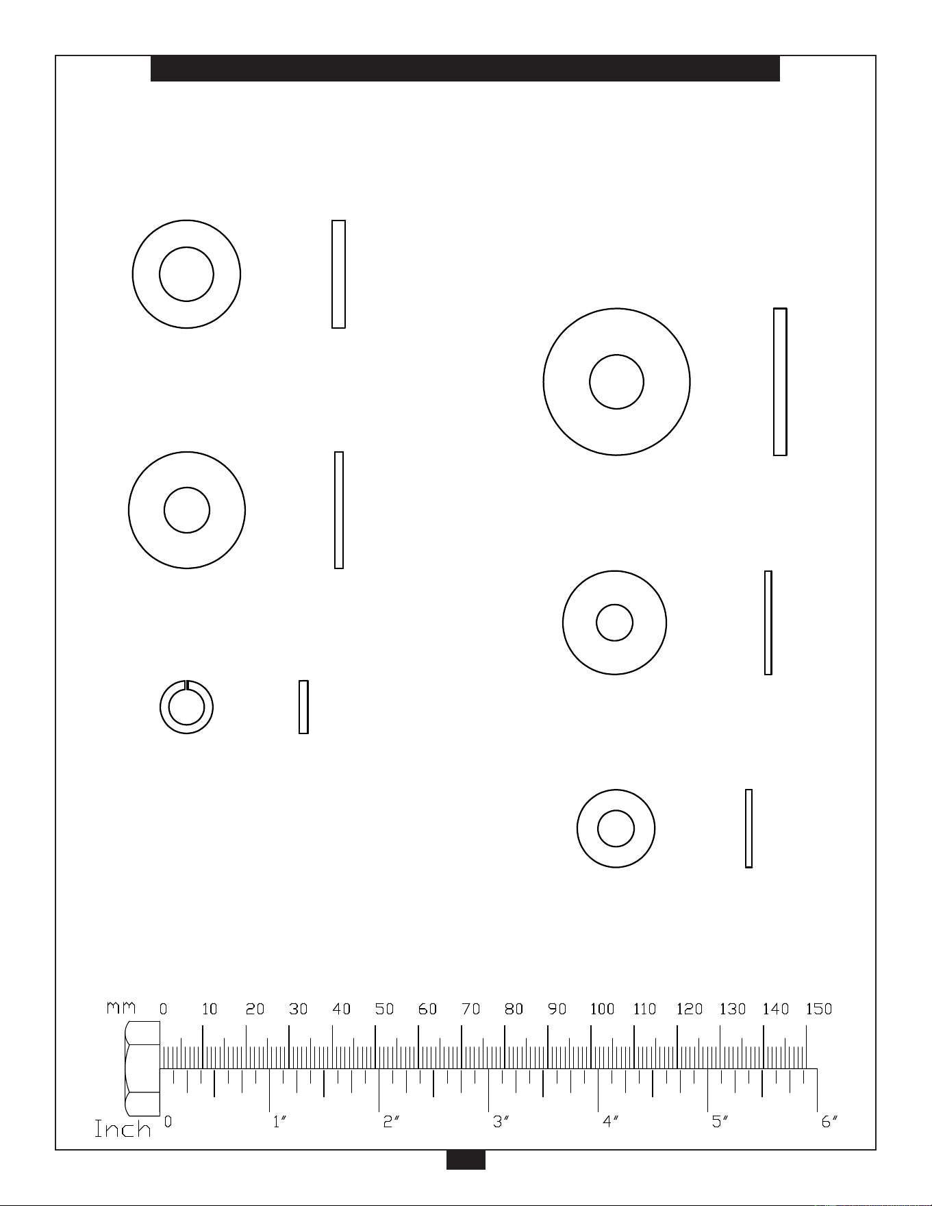
H a r d w a r e
( T o S c a l e )
Part# 22 M12 (Φ34) Washer Qty. 30
G L P H - 1 1 0 0 H A R D W A R E
( s h o w n i n a c t u a l s i z e )
KEY #B1 NYLON LOCK NUT M12
QTY.19
KEY #B2 NYLON LOCK NUT M10
QTY.4
KEY #B3 NYLON LOCK NUT M8
QTY.4
KEY #C1 WASHER M12(Ø25)
QTY.8
KEY #C2 WASHER M12(Ø34)
QTY.30
KEY #C4 WASHER M10(Ø27)
QTY.10
KEY #C5 WASHER M8(Ø24)
QTY.17
KEY #C6 SPRING LOCK WASHER
M8 QTY.17
KEY #C7 WASHER M8(Ø18)
QTY.8
1d
Part# 25 M8 (Φ24) Washer Qty. 17
G L P H - 1 1 0 0 H A R D W A R E
( s h o w n i n a c t u a l s i z e )
KEY #B1 NYLON LOCK NUT M12
QTY.19
KEY #B2 NYLON LOCK NUT M10
QTY.4
KEY #B3 NYLON LOCK NUT M8
QTY.4
KEY #C1 WASHER M12(Ø25)
QTY.8
KEY #C2 WASHER M12(Ø34)
QTY.30
KEY #C4 WASHER M10(Ø27)
QTY.10
KEY #C5 WASHER M8(Ø24)
QTY.17
KEY #C6 SPRING LOCK WASHER
M8 QTY.17
KEY #C7 WASHER M8(Ø18)
QTY.8
1d
Part# 27 M8 (Φ18) Washer Qty. 12
G L P H - 1 1 0 0 H A R D W A R E
( s h o w n i n a c t u a l s i z e )
KEY #B1 NYLON LOCK NUT M12
QTY.19
KEY #B2 NYLON LOCK NUT M10
QTY.4
KEY #B3 NYLON LOCK NUT M8
QTY.4
KEY #C1 WASHER M12(Ø25)
QTY.8
KEY #C2 WASHER M12(Ø34)
QTY.30
KEY #C4 WASHER M10(Ø27)
QTY.10
KEY #C5 WASHER M8(Ø24)
QTY.17
KEY #C6 SPRING LOCK WASHER
M8 QTY.17
KEY #C7 WASHER M8(Ø18)
QTY.8
1d
Part# 21 M12 (Φ25) Washer Qty. 8
G L P H - 1 1 0 0 H A R D W A R E
( s h o w n i n a c t u a l s i z e )
KEY #B1 NYLON LOCK NUT M12
QTY.19
KEY #B2 NYLON LOCK NUT M10
QTY.4
KEY #B3 NYLON LOCK NUT M8
QTY.4
KEY #C1 WASHER M12(Ø25)
QTY.8
KEY #C2 WASHER M12(Ø34)
QTY.30
KEY #C4 WASHER M10(Ø27)
QTY.10
KEY #C5 WASHER M8(Ø24)
QTY.17
KEY #C6 SPRING LOCK WASHER
M8 QTY.17
KEY #C7 WASHER M8(Ø18)
QTY.8
1d
Part# 24 M10 (Φ27) Washer Qty. 10
G L P H - 1 1 0 0 H A R D W A R E
( s h o w n i n a c t u a l s i z e )
KEY #B1 NYLON LOCK NUT M12
QTY.19
KEY #B2 NYLON LOCK NUT M10
QTY.4
KEY #B3 NYLON LOCK NUT M8
QTY.4
KEY #C1 WASHER M12(Ø25)
QTY.8
KEY #C2 WASHER M12(Ø34)
QTY.30
KEY #C4 WASHER M10(Ø27)
QTY.10
KEY #C5 WASHER M8(Ø24)
QTY.17
KEY #C6 SPRING LOCK WASHER
M8 QTY.17
KEY #C7 WASHER M8(Ø18)
QTY.8
1d
Part# 26 M8 Spring Washer Qty. 21
G L P H - 1 1 0 0 H A R D W A R E
( s h o w n i n a c t u a l s i z e )
KEY #B1 NYLON LOCK NUT M12
QTY.19
KEY #B2 NYLON LOCK NUT M10
QTY.4
KEY #B3 NYLON LOCK NUT M8
QTY.4
KEY #C1 WASHER M12(Ø25)
QTY.8
KEY #C2 WASHER M12(Ø34)
QTY.30
KEY #C4 WASHER M10(Ø27)
QTY.10
KEY #C5 WASHER M8(Ø24)
QTY.17
KEY #C6 SPRING LOCK WASHER
M8 QTY.17
KEY #C7 WASHER M8(Ø18)
QTY.8
1d
37
59
M
59
5
20
25
20
25
P
33
33
1
1
22
22
25
11
35
25
8
25
8
49
40
38
14
38
20
26
27
40
49
13
22
25
26
25
26
26
2
22
22
14
27
26
30
20
26
27
14
49
60
40
49
39
22
18
21
28
21
21
18
32
32
22
18
21
3
25
26
10
25
26
10
25
26
10
25
26
10
2
18
21
22
2
32
3
32
34
18
22
18
32
8
25
8
25
25
25
20
20
5
22
37
59
37
59
33
33
22
1
22
1
25
26
2
2
22
22
22
18
22
18
18
22
15
26
26
27
10
27
26
27
26
24
19
24
10
26
27
10
10
7
7
26
27
10
26
10
26
7
24
7
24
24
19
24
6
24
19
44
15
15
AB
14
49
13
40
12
20
49
49
31
22
10
10
4
W
24
24
27
W
27
AB
R
60
21
18
11
35
25
EXPLODED VIEW
DIAGRAM GLPH1100
3
21
C
40
42
47
12
27
26
42
38
38
40
60
40
22
6
31
29
9
9
18
22
18
22
22
22
18
18
22
18
21
22
4
22
9
50
22
37
33
33
51
Y
41
K
28
N
3
Z
60
45
46
42
49
40
39
47
52
16
58
H
9
O
52
17
32
AA
36
T
U
S
D
34
54
53
AC
33
33
50
L
F
E
32
57
V
4
J
10
2
X
43
15
AD
22
56
24
Q
19
29
30
42
44
B
P
G
A
22
18
43
27
41
26
48
29
30
18
22
30
20
55
18
18
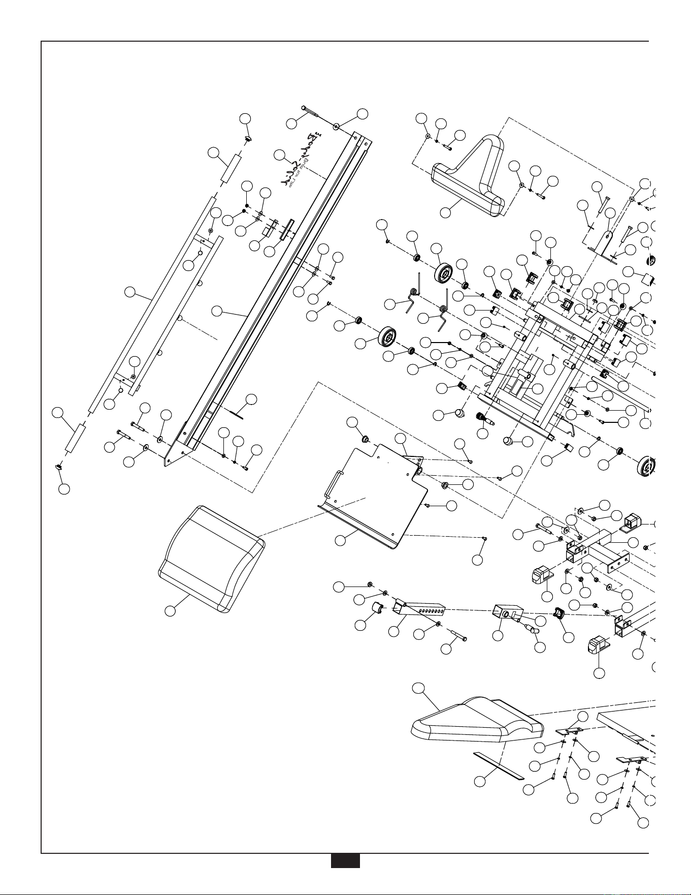
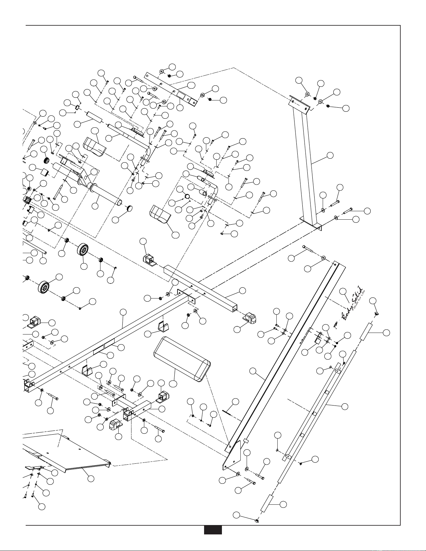
ExPLODED VIEW
DIAGRAM
GLPH1100
45
60
by
by
®
®
45
61
37
59
M
59
5
20
25
20
25
P
33
33
1
1
22
22
25
11
35
25
8
25
8
49
40
38
14
38
20
26
27
40
49
13
22
25
26
25
26
26
2
22
22
14
27
26
30
20
26
27
14
49
60
40
49
39
22
18
21
28
21
21
18
32
32
22
18
21
3
25
26
10
25
26
10
25
26
10
25
26
10
2
18
21
22
2
32
3
32
34
18
22
18
32
8
25
8
25
25
25
20
20
5
22
37
59
37
59
33
33
22
1
22
1
25
26
2
2
22
22
22
18
22
18
18
22
15
26
26
27
10
27
26
27
26
24
19
24
10
26
27
10
10
7
7
26
27
10
26
10
26
7
24
7
24
24
19
24
6
24
19
44
15
15
AB
14
49
13
40
12
20
49
49
31
22
10
10
4
W
24
24
27
W
27
AB
R
60
21
18
11
35
25
EXPLODED VIEW
DIAGRAM GLPH1100
3
21
C
40
42
47
12
27
26
42
38
38
40
60
40
22
6
31
29
9
9
18
22
18
22
22
22
18
18
22
18
21
22
4
22
9
50
22
37
33
33
51
Y
41
K
28
N
3
Z
60
45
46
42
49
40
39
47
52
16
58
H
9
O
52
17
32
AA
36
T
U
S
D
34
54
53
AC
33
33
50
L
F
E
32
57
V
4
J
10
2
X
43
15
AD
22
56
24
Q
19
29
30
42
44
B
P
G
A
22
18
43
27
41
26
48
29
30
18
22
30
20
55
18
18
by
by
®
®

1900 S. Des Plaines Ave.
Forest Park, Il 60130
1 (800) 556-3113
Hours: M-F 8:30 - 5:00
www.bodysolid.com
c
Copyright 2010. Body-Solid. All rights reserved. Body-Solid reserves the right to change design and specications when we feel it will improve the product.
Body-Solid machines maintain several patented and patent pending features and designs. All rights reserved on all design patents and utility patents.
by
by
®
®