

&
Assembly Instructions
OWNER’S MANUAL
V. GFT100-20210315
GFT100
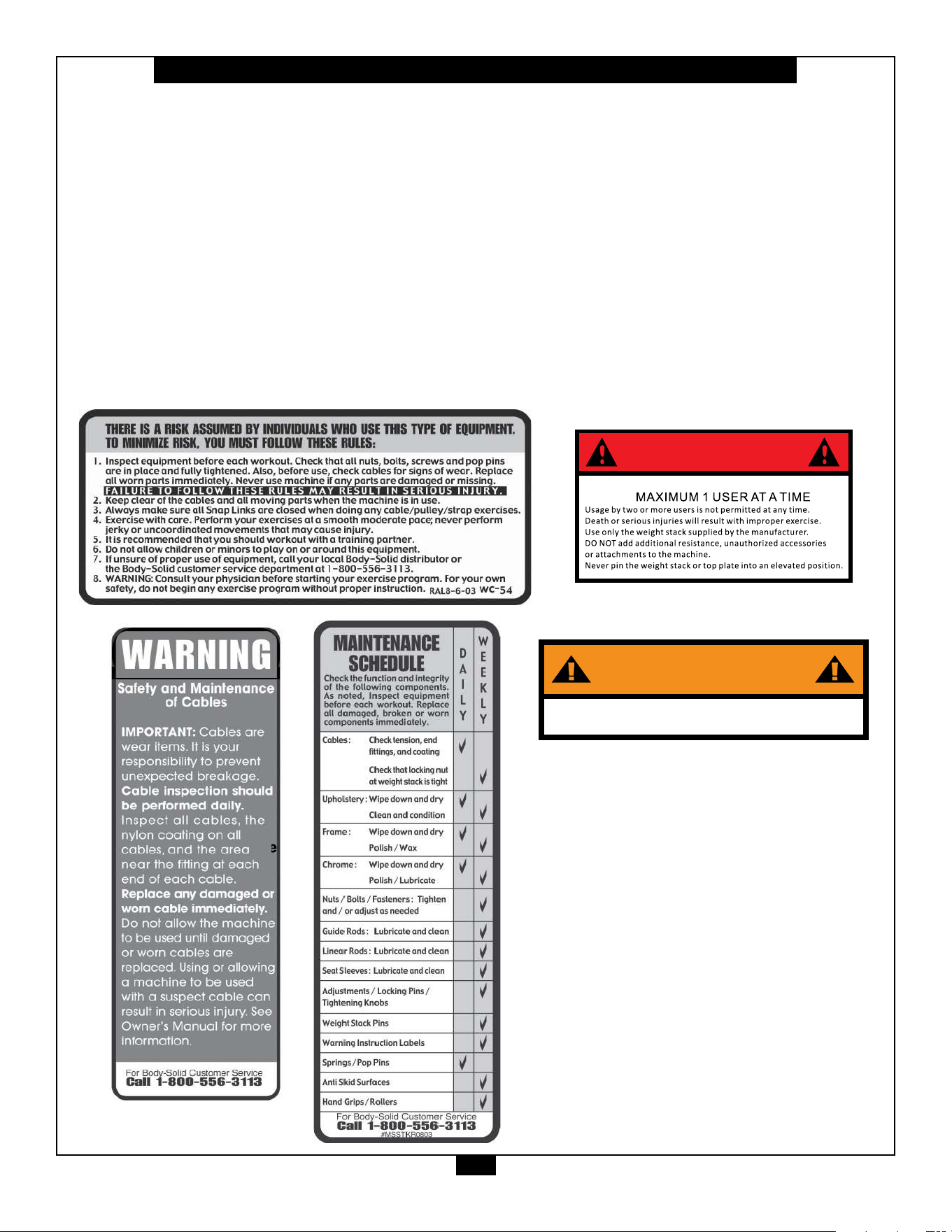
Warning, Safety & Maintenance
2
Be sure that all users carefully read and understand all
warning, safety and maintenance labels on the machine
before each use. Failure to do so may result in death or
serious injury.
It is imperative that you retain this Owner’s Manual and be
sure all warning labels are legible and intact. Replacement
Owner’s Manuals and warning labels are available from your
local Body-Solid dealer.
If you have any questions about the operation, set up or
maintenance of this machine please call our customer service
department at 1 (800) 556-3113.
DANGER
WARNING
Bolt machine to the ground before use

Table of Contents
3
• SAFETY INSTRUCTIONS.............................. PAGE 4
• PREPARATION............................................... PAGE 5
• PART / HARDWARE LIST............................... PAGE 6
• HARDWARE ILLUSTRATION......................... PAGE 8
• ASSEMBLY INSTRUCTIONS......................... PAGE 14
• EXPLODED VIEW.......................................... PAGE 26
• CONTACT PAGE............................................ PAGE 28

Important Safety Instructions
4
Beforebeginninganytnessprogram,youshouldobtainacompletephysicalexaminationfromyourphysician.
Il est conseille de subir un examen medical complet avant d’entreprendre tout programme d’exercise.
Si vous avez des etourdissements ou des faiblesses, arretez les exercices immediatement.
Antes de comenzar cualquier programma de ejercicios, deberias tener un examen sico con su doctor.
When using exercise equipment, you
should always take basic precautions,
including the following:
m ReadallinstructionsbeforeusingtheGFT100.
Theseinstructionsarewrittentoensureyoursafety
andtoprotecttheunit.
m Do not remove any safety labels from the
machine.
m Donotallowchildrenonorneartheequipment.
m Usetheequipmentonlyforitsintendedpurpose
asdescribedinthisguide.Donotuseaccessory
attachmentsthatarenotrecommendedbythe
manufacturer.Suchattachmentsmightcause
injuries.
m Wearproperexerciseclothingandshoesforyour
workout,nolooseclothing.
m Keephands,limbs,looseclothing,andlonghairwell
outofthewayofallmovingparts.
m Usecarewhengettingonorotheunit.
m Donotoverexertyourselforworktoexhaustion.
m Ifyoufeelanypainorabnormalsymptoms,stop
yourworkoutimmediatelyandconsultyour
physician.
m Neveroperateunitwhenithasbeendroppedor
damaged.Returntheequipmenttoaservice
centerforexaminationandrepair.
m Neverdroporinsertobjectsintoanyopeningin
theequipment.
m Alwayschecktheunitanditscablesbeforeeach
use.Makesurethatallfastenersandcablesare
secureandingoodworkingcondition.
m Donotusetheequipmentoutdoorsornearwater.
Personal Safety During Assembly
m Beforebeginningassembly,pleasetakethetime
toreadtheinstructionsthoroughly.
m Readeachstepintheassemblyinstructionsand
followthestepsinsequence.Donotskipahead.
Ifyouskipahead,youmaylearnlaterthatyou
havetodisassemblecomponentsandthatyou
mayhavedamagedtheequipment.
m Assembleandoperatethe
GFT100onasolid,
levelsurface.Locatetheunitafewfeetfromthe
wallsorfurnituretoprovideeasyaccess.
TheGFT100 isdesignedforyourenjoyment.By
followingtheseprecautionsandusingcommonsense,
youwillhavemanysafeandpleasurablehoursof
healthfulexercisewithyourBody-SolidFunctional
Trainer.
Afterassembly,youshouldcheckallfunctionsto
ensurecorrectoperation.Ifyouexperienceproblems,
rstrechecktheassemblyinstructionstolocateany
possibleerrorsmadeduringassembly.Ifyouareunable
tocorrecttheproblem,callthedealerfromwhomyou
purchasedthemachineorcall1-800-556-3113forthe
dealernearestyou.
Obtaining Service
PleaseusethisOwner’sManualtomakesurethatall
partshavebeenincludedinyourshipment.When
orderingparts,youmustusethepartnumberand
descriptionfromthisOwner’sManual.Useonly
Body-Solidreplacementpartswhenservicingthis
machine.Failuretodosowillvoidyourwarrantyand
couldresultinpersonalinjury.
Forinformationaboutproductoperationorservice,
checkouttheocialBody-Solidwebsiteat
www.bodysolid.comorcontactanauthorized
Body-SoliddealeroraBody-Solidfactory-authorized
servicecompanyorcontactBody-Solidcustomer
serviceatoneofthefollowing:
Toll Free: 1-800-556-3113
Phone: 1-708-427-3555
Fax: 1-708-427-3556
Hours: M-F 8:30-5:00 CST
E-Mail: [email protected]
Or write to: Body-Solid, Inc.
Service Department
1900 S. Des Plaines Ave.
Forest Park, IL 60130 USA
Retain this Owner’s Manual for future
reference. If you need to order replacement
parts please be prepared to provide the
following information when contacting us so
that we can assist you better.
1. Model Number
2. Place of Purchase
3. Serial Number (S/N)
4. Part # and Description
Preparation
5
ThankyouforpurchasingtheGFT100.ThisProductispartoftheBody-Solidlineofqualitystrengthtraining
machines,whichletsyoutargetspecicmusclegroupstoachievebettermuscletoneandoverallbody
conditioning. To maximize your use of the equipment please study this Owner’s Manual thoroughly.
Body-Solidcontinuallyseekswaystoimprovetheperformance,specicationsandproductmanualsinordertoensurethatonly
superiorproductsarereleasedfromourfactories.Pleasetakethetimetocarefullyreadthroughthismanualthoroughly.Instructions
containedinthisdocumentarenotintendedtocoveralldetailsorvariationspossiblewithBody-Solidequipment,ortocoverevery
contingencythatmaybemetinconjunctionwithinstallation,operation,maintenanceortroubleshootingoftheequipment.Even
thoughwehavepreparedthismanualwithextremecare,neitherthepublishernortheauthorcanacceptresponsibilityforanyerrors
in,oromissionfrom,theinformationgiven.Shouldadditionalinformationberequired,orshouldsituationsarisethatarenotcovered
bythismanual,themattershouldbedirectedtoyourlocalBody-Solidrepresentative,ortheServiceDepartmentatBody-SolidInc.
inForestPark,Illinois.
Required Tools
Thebasictoolsthatyoumustobtainbeforeassembling
the
GFT100includebutarenotlimitedto:
m StandardWrenchSet
m MetricWrenchSet
m AdjustableWrench
Installation Requirements
Followtheseinstallationrequirementswhenassembling
the
GFT100:
Setupthe
GFT100onasolid,atsurface.Asmooth,
atsurfaceunderthemachinehelpskeepitlevel.A
levelmachinehasfewermalfunctions.
Provideamplespacearoundthemachine.Open
spacearoundthemachineallowsforeasieraccess.
Insertallboltsinthesamedirection.Foraesthetic
purposes,insertallboltsinthesamedirectionunless
specied(intextorillustrations)todootherwise.
Leaveroomforadjustments.Tightenfastenerssuchas
bolts,nuts,andscrewssotheunitisstable,butleave
roomforadjustments.Donotfullytightenfasteners
untilinstructedintheassemblystepstodoso.
Fill out and mail the warranty card.
Assembly Tips
Readall“Notes”oneachpagebeforebeginningeach
step.
Whileyoumaybeabletoassemblethe
GFT100using
theillustrationsonly,importantsafetynotesandother
tipsareincludedinthetext.
Somepiecesmayhaveextraholesthatyouwillnotuse.
Useonlythoseholesindicatedintheinstructionsand
illustrations.
NOTE: Withsomanyassembledparts,proper
alignmentandadjustmentiscritical.While
tighteningthenutsandbolts,besuretoleave
roomforadjustments.
CAUTION: Obtainassistance!Ifyoufeellikeyoucan’t
assemblethe
GFT100byyourselfthendo
notattempttodosoasthiscouldresultin
inju
ry.Reviewtheinstallationrequirements
beforeproceedingwiththefollowingsteps.
YourS/N#can
befoundhere
↑

6
GFT100 Parts &Hardware List
Part# Qty Description
A
B
C
D
E
F
G
H
J
K
L
M
N
P
Q
R
S
T
U
1
2
3
4
5
6
7
8
9
10
11
12
13
14
15
2
2
2
2
2
4
2
1
4
2
1
2
1
1
1
4
2
2
2
2
12
8
14
24
2
2
16
4
4
2
4
88
26
24
BASE FRAME
MIDDLE UPRIGHT
REAR UPRIGHT
FRONT CHROME UPRIGHT
TOP FRAME
CHROME GUIDE ROD
DOUBLE PULLEY BRACKET
RIGHT SLIDING HANDLE
UPRIGHT BRACKET
PULLEY BRACKET
CHIN UP BAR
CENTER CROSSMEMBER
STORAGE TRAY
PLACARD PLATE
LEFT SLIDING HANDLE
WEIGHT RISER
LEFT LOGO PLATE
RIGHT LOGO PLATE
CHIN UP BAR BRACKET
M12x115mmHEXHEADBOLT
M10x125mmHEXHEADBOLT
M10x80mmHEXHEADBOLT
M10x50mmHEXHEADBOLT
M10x20mmBUTTONHEADCAPSCREW
M8x75mmHEXHEADBOLT
M8x70mmHEXHEADBOLT
M8x15mmBUTTONHEADCAPSCREW
M8x8mmSETSCREW
M6x12mmBUTTONHEADCAPSCREW
M10x50mmSOCKETHEADCAPSCREW
M12 WASHER
M10 WASHER
M10 LOCK WASHER
M8 WASHER

7
GFT100 Parts &Hardware List
Part# Qty Description
16
17
18
19
20
21
22
23
24
25
26
27
28
29
30
31
32
33
34
35
36
37
38
39
40
41
42
43
2
32
4
6
2
16
10
4
2
2
2
2
4
2
2
4
2
2
2
4
4
4
1
1
1
2
2
1
M12 NYLON LOCK NUT
M10 NYLON LOCK NUT
M8 NYLON LOCK NUT
M12 HEX NUT
M12 LOCK WASHER
M8 LOCK WASHER
PLASTICPULLEY,
ø117mm
ALUMINUMPULLEY,ø90mm
PLASTICPULLEY,ø90mm
CABLE CONNECTOR BOLT
CABLE CONNECTOR
ACCESSORY CONNECTOR
PULLEY SPACER
CABLE
TOP PLATE
RUBBER DONUT
WEIGHT SELECTOR ROD
WEIGHT SELECTOR PIN
POP PIN
NYLON BUSHING
METAL BUSHING
SHAFT COLLAR
LONG STRAIGHT BAR
TRICEP ROPE
LONG STRAP
SNAP LINK
STRAP HANDLE
EXERCISE PLACARD
45
8
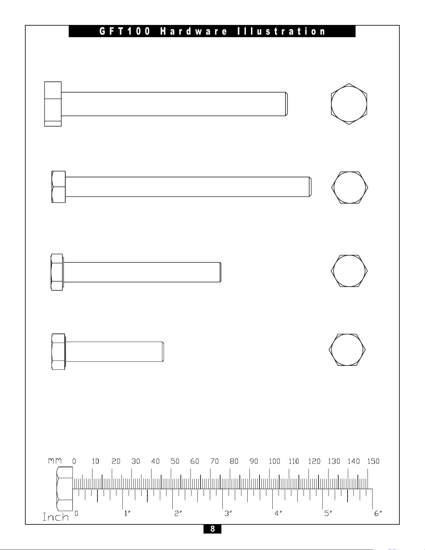
GFT100 Hardware Illustration
Part#2 HEXHEADBOLTM10x125mm QTY. 12
Part#1 HEXHEADBOLTM12x115mm QTY. 2
Part#3 HEXHEADBOLTM10x80mm QTY. 8
Part#4 HEXHEADBOLTM10x50mm QTY. 14
45
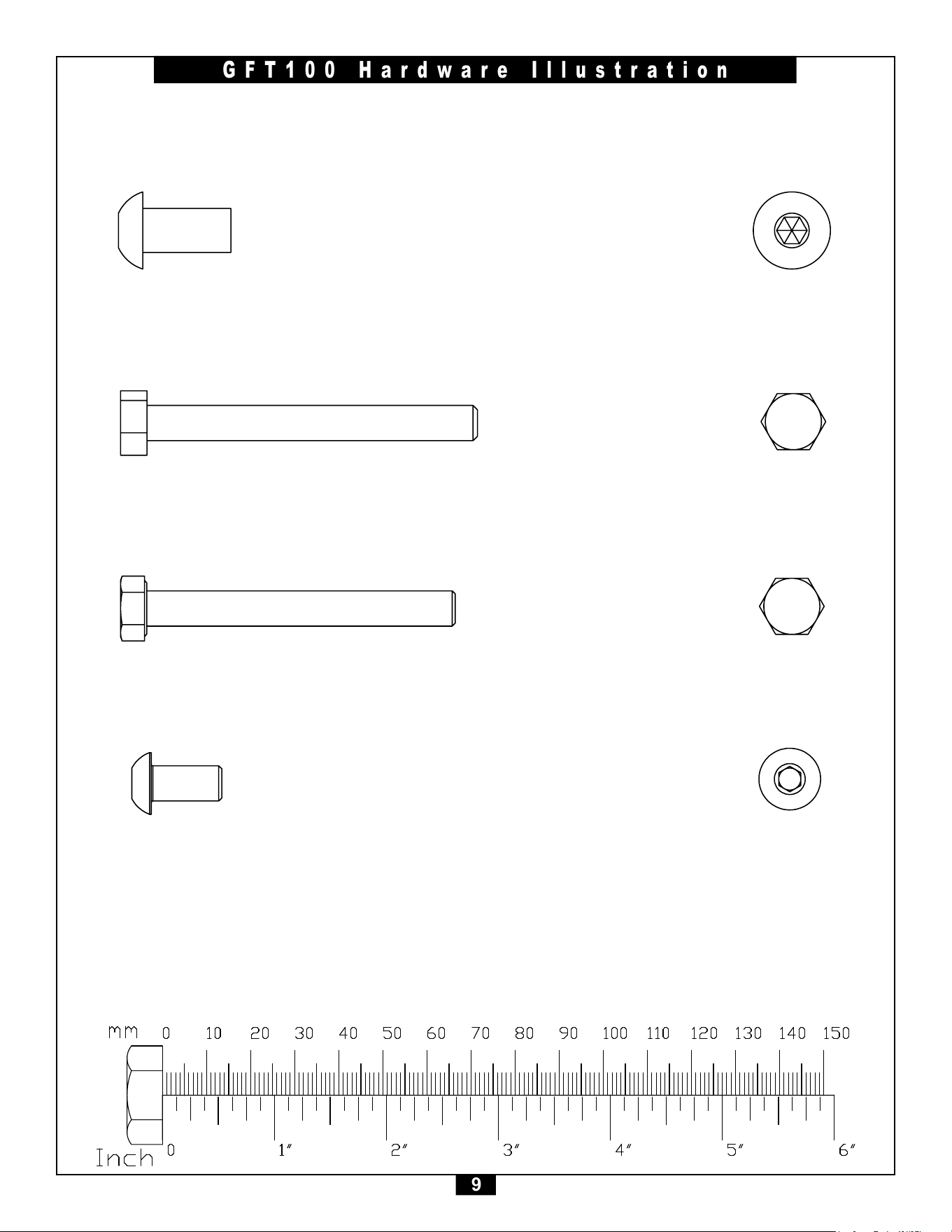
9
GFT100 Hardware Illustration
Part#6 HEXHEADBOLTM8x75mm QTY. 2
Part#5 BUTTONHEADCAPSCREWM10x20mm QTY. 24
Part#7 HEXHEADBOLTM8x70mm QTY. 2
Part#8 BUTTONHEADCAPSCREWM8x15mm QTY. 16
45
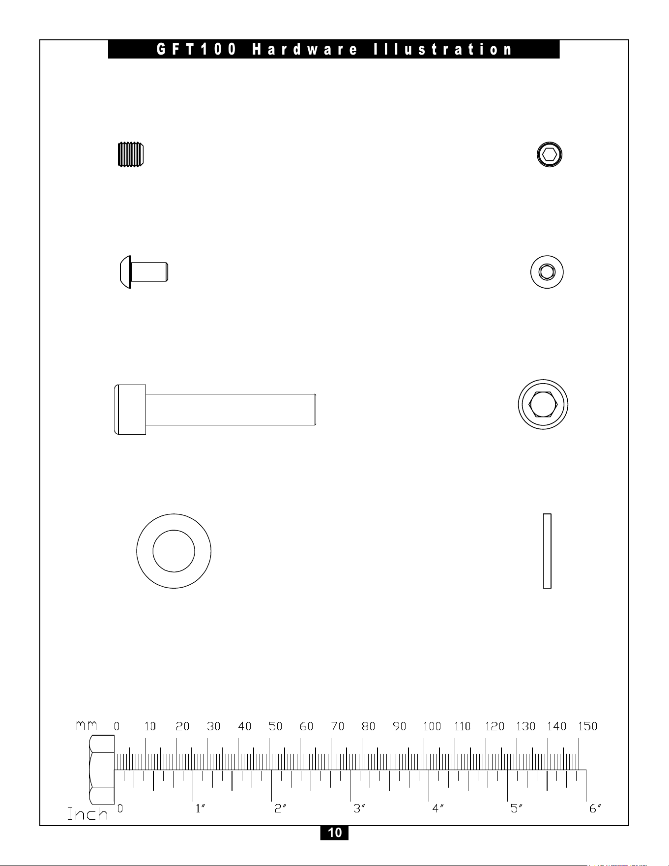
10
GFT100 Hardware Illustration
Part#10 BUTTONHEADCAPSCREWM6x12mm QTY. 4
Part#9 SETSCREWM8x8mm QTY. 4
Part#11 SOCKETHEADCAPSCREWM10x50mm QTY. 2
Part#12 M12WASHER QTY. 4
UNLESS OTHERWISE SPECIFIED:
CHECKED
SIZE
APPLICATION
TITLE:
PROPRIETARY AND CONFIDENTIAL
INTERPRET GEOMETRIC
TOLERANCING PER:
Q.A.
FINISH
DWG. NO.
DATE
USED ON
A
DIMENSIONS ARE IN INCHES
TOLERANCES:
FRACTIONAL
ANGULAR: MACH
BEND
TWO PLACE DECIMAL
THREE PLACE DECIMAL
NEXT ASSY
MATERIAL
NAME
REV
DO NOT SCALE DRAWING
SCALE: 2:1
GBT 70.1-2000X1(GB_FASTENER_SCREWS_HSHCS M10X16-N)
ENG APPR.
THE INFORMATION CONTAINED IN THIS
DRAWING IS THE SOLE PROPERTY OF
<INSERT COMPANY NAME HERE>. ANY
REPRODUCTION IN PART OR AS A WHOLE
WITHOUT THE WRITTEN PERMISSION OF
<INSERT COMPANY NAME HERE> IS
PROHIBITED.
COMMENTS:
DRAWN
MFG APPR.
SHEET 1 OF 1
2 1
A
B
A
B
12
<COMPANY NAME>
45
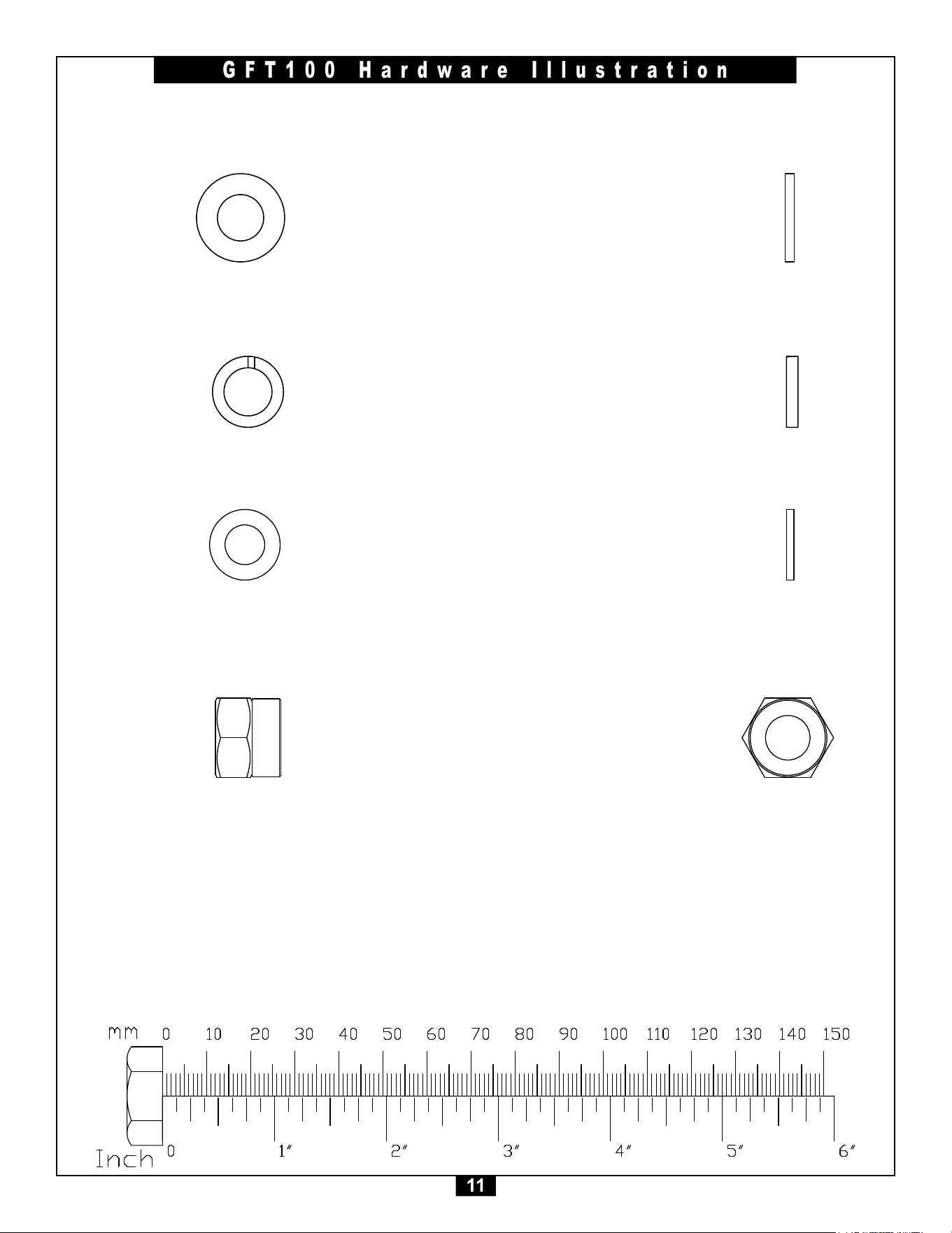
11
GFT100 Hardware Illustration
Part#14 M10LOCKWASHER QTY. 26
Part#13 M10WASHER QTY. 88
Part#15 M8WASHER QTY. 24
Part#16 M12NYLONLOCKNUT QTY. 2
45
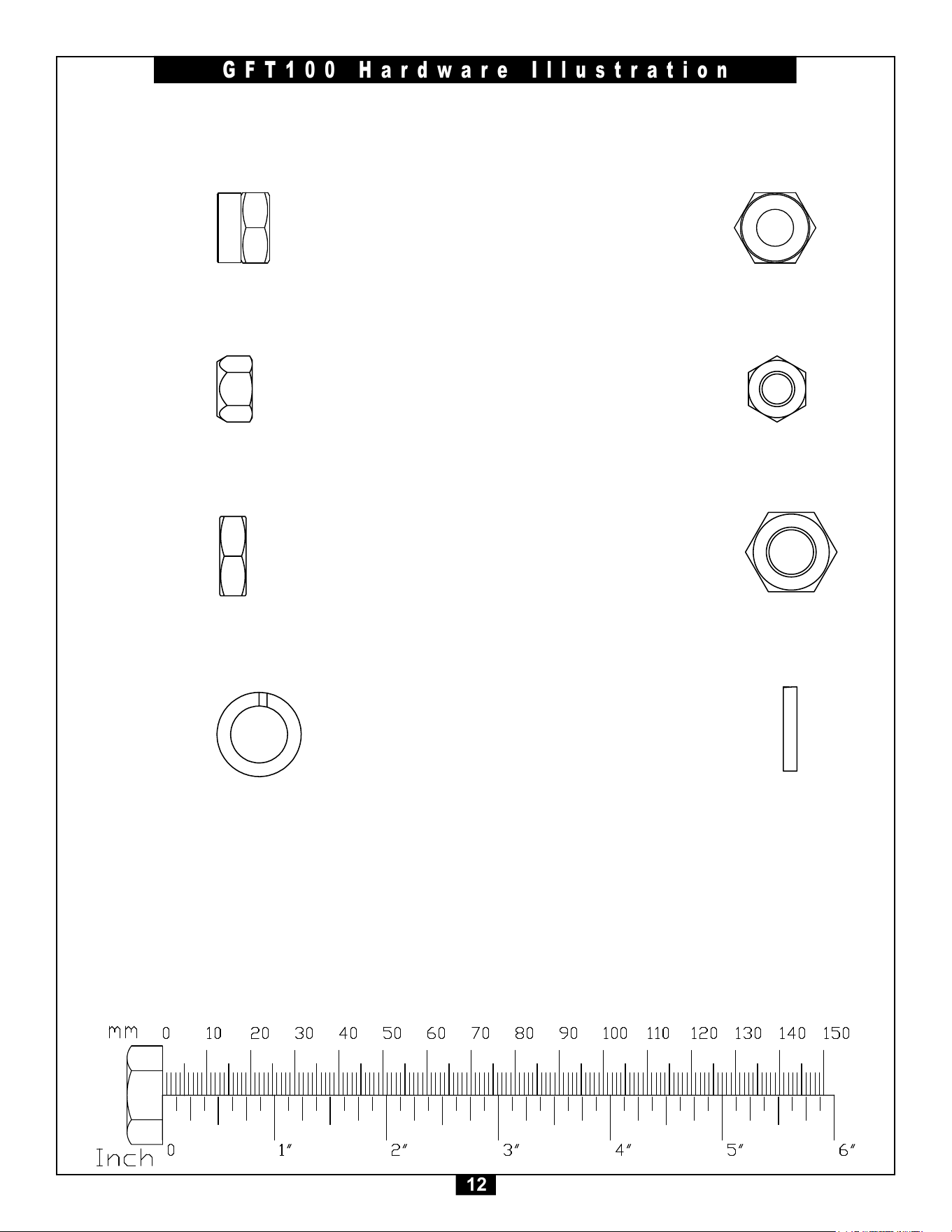
12
GFT100 Hardware Illustration
Part#18 M8NYLONLOCKNUT QTY. 4
Part#17 M10NYLONLOCKNUT QTY. 32
Part#19 M12HEXNUT QTY. 6
Part#20 M12LOCKWASHER QTY. 2
UNLESS OTHERWISE SPECIFIED:
CHECKED
SIZE
APPLICATION
TITLE:
PROPRIETARY AND CONFIDENTIAL
INTERPRET GEOMETRIC
TOLERANCING PER:
Q.A.
FINISH
DWG. NO.
DATE
USED ON
A
DIMENSIONS ARE IN INCHES
TOLERANCES:
FRACTIONAL
ANGULAR: MACH
BEND
TWO PLACE DECIMAL
THREE PLACE DECIMAL
NEXT ASSY
MATERIAL
NAME
REV
DO NOT SCALE DRAWING
SCALE: 2:1
HEX NUT M12
ENG APPR.
THE INFORMATION CONTAINED IN THIS
DRAWING IS THE SOLE PROPERTY OF
<INSERT COMPANY NAME HERE>. ANY
REPRODUCTION IN PART OR AS A WHOLE
WITHOUT THE WRITTEN PERMISSION OF
<INSERT COMPANY NAME HERE> IS
PROHIBITED.
COMMENTS:
DRAWN
MFG APPR.
SHEET 1 OF 1
2 1
A
B
A
B
12
<COMPANY NAME>
45
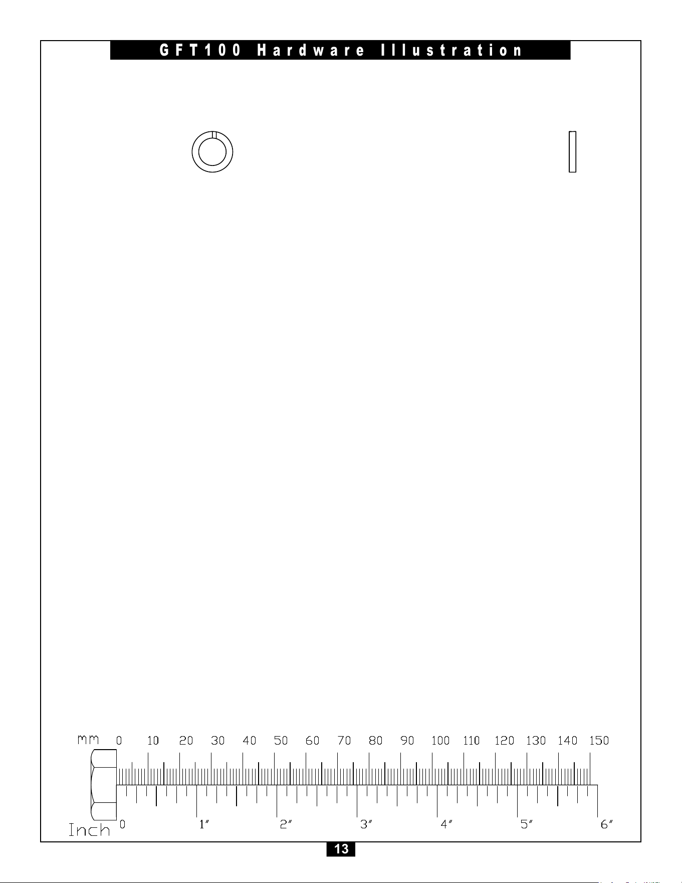
13
GFT100 Hardware Illustration
Part#21 M8LOCKWASHER QTY. 16

14
STEP
1
Be careful to assemble all components
in the sequence they are presented.
NOTE:
Finger tighten all hardware in this step. DO NOT wrench tighten until instructed.
Some components may be pre-assembled. Nylon lock nuts will not fully screw onto
bolts, they must be wrench tightened to fully go on.
RIGHT SIDE ASSEMBLY
1A. AttachMiddleUpright(B)&RearUpright(C)toBase
Frame(A)using:
6 - (#5) M10x20mm Button Head Cap Screw
6 - (#13) M10 Washer
6 - (#14) M10 Lock Washer
1B. AttachFrontChromeUpright(D)toBaseFrames(A)using:
2 - (#3) M10x80mm Hex Head Bolt
4 - (#13) M10 Washer
2 - (#17) M10 Nylon Lock Nut
1C. InsertRightSlidingHandle(H)ontoFrontChromeUpright(D).
1D. AttachFrontChromeUpright(D),MiddleUpright(B) & Rear
Upright(C)toTopFrame(A)using:
6 - (#5) M10x20mm Button Head Cap Screw
1 - (#3) M10x80mm Hex Head Bolt
8 - (#13) M10 Washer
6 - (#14) M10 Lock Washer
1 - (#17) M10 Nylon Lock Nut
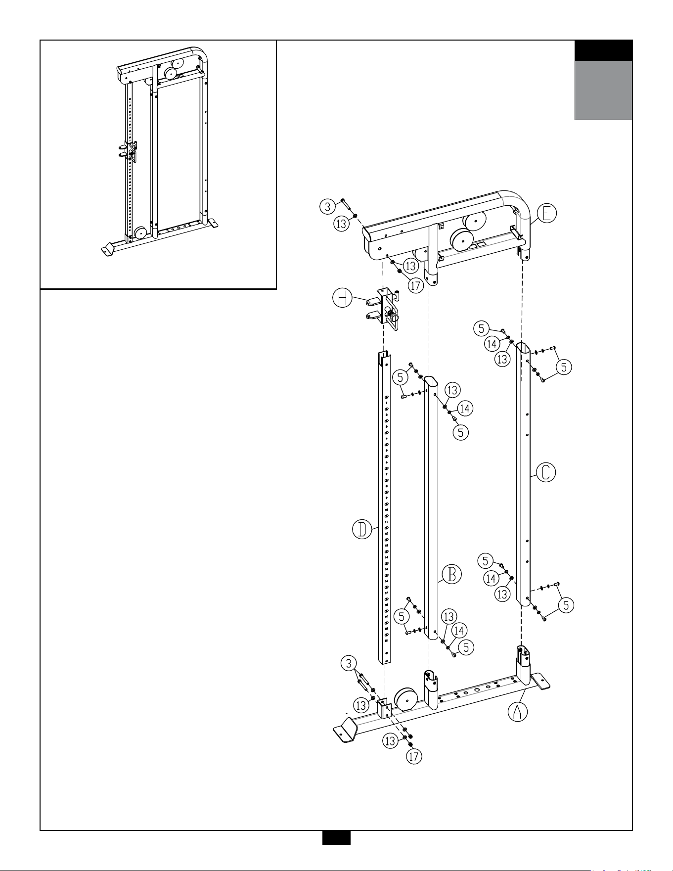
STEP
1
AboveshowsStep1assembledandcompleted.
15

16
STEP
2
Be careful to assemble all components
in the sequence they are presented.
NOTE:
Finger tighten all hardware in this step. DO NOT wrench tighten until instructed.
Some components may be pre-assembled. Nylon lock nuts will not fully screw onto
bolts, they must be wrench tightened to fully go on.
LEFT SIDE ASSEMBLY
2A. AttachMiddleUpright(B)&RearUpright(C)toBase
Frame(A)using:
6 - (#5) M10x20mm Button Head Cap Screw
6 - (#13) M10 Washer
6 - (#14) M10 Lock Washer
2B. AttachFrontChromeUpright(D)toBaseFrames(A)using:
2 - (#3) M10x80mm Hex Head Bolt
4 - (#13) M10 Washer
2 - (#17) M10 Nylon Lock Nut
2C. InsertLeftSlidingHandle(Q)ontoFrontChromeUpright(D).
2D. AttachFrontChromeUpright(D),MiddleUpright(B) & Rear
Upright(C)toTopFrame(A)using:
6 - (#5) M10x20mm Button Head Cap Screw
1 - (#3) M10x80mm Hex Head Bolt
8 - (#13) M10 Washer
6 - (#14) M10 Lock Washer
1 - (#17) M10 Nylon Lock Nut
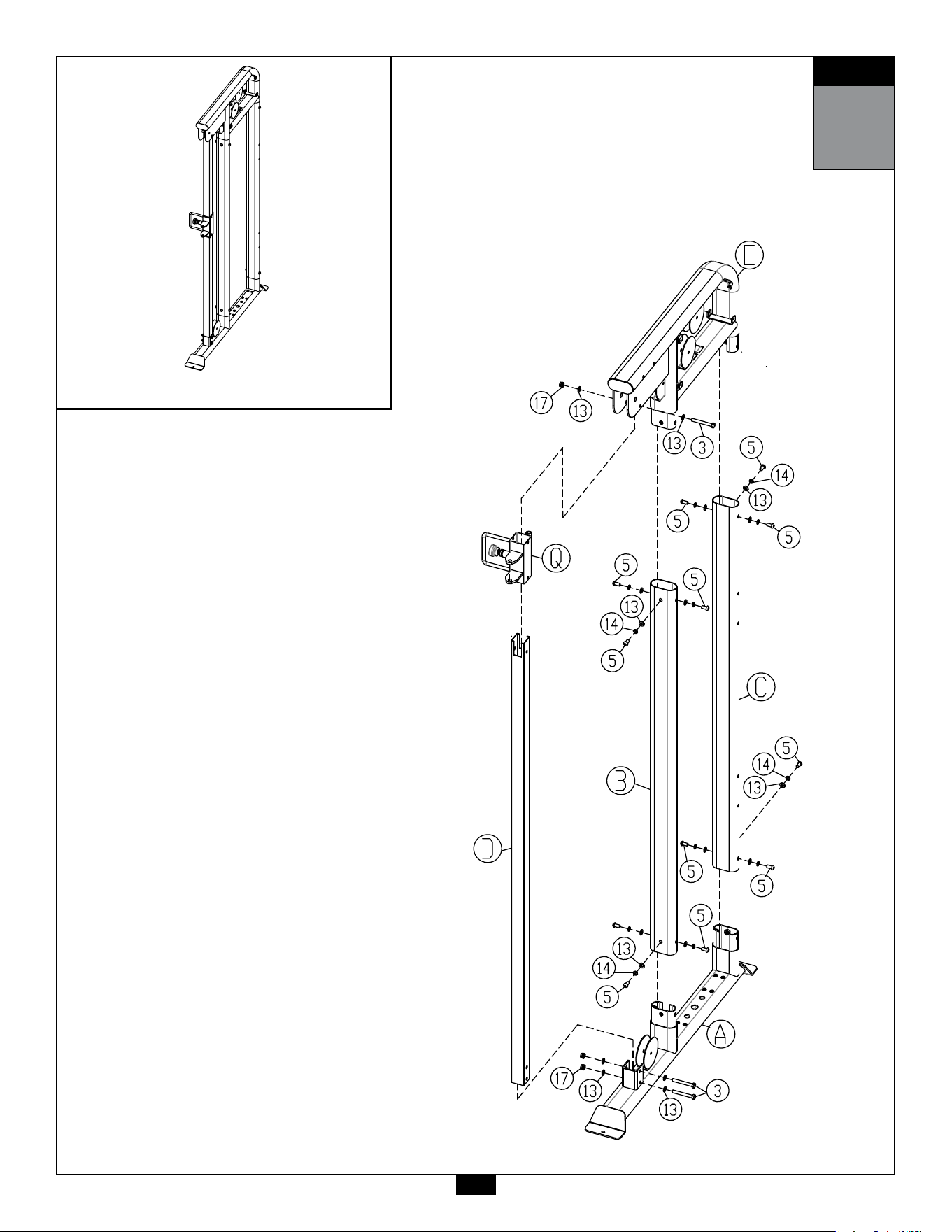
STEP
2
AboveshowsStep2assembledandcompleted.
17

18
STEP
3
Be careful to assemble all components
in the sequence they are presented.
NOTE:
Wrench tighten ALL hardware at the end of STEP 3E. Some components may be
pre-assembled. Nylon lock nuts will not fully screw onto bolts, they must be wrench
tighten to fully go on.
3A. AttachTwoCenterCrossmembers(M)tobothRearUprights(C)
using:
8 - (#2) M10x125mm Hex Head Bolt
16 - (#13) M10 Washer
8 - (#17) M10 Nylon Lock Nut
4 - (J) Upright Bracket
3B. AttachChinUpBar(L)tobothTopFrames(E)using:
8 - (#2) M10x125mm Hex Head Bolt
16 - (#13) M10 Washer
8 - (#17) M10 Nylon Lock Nut
2 - (U) Chin Up Bar Bracket
3C. AttachDoublePulleyBrackets(G)tobothSlidingHandles(H & Q)
using:
2 - (#1) M12x115mm Hex Head Bolt
4 - (#12) M12 Washer
2 - (#16) M12 Nylon Lock Nut
4 - (#36) Metal Bushing
3D. AttachPlacardPlate(P)toLowerCenterCrossmember(M)using:
2 - (#7) M8x70mm Hex Head Bolt
4 - (#15) M8 Washer
2 - (#18) M8 Nylon Lock Nut
3E. AttachPlacardPlate(P),StorageTray(N)andUpperCenter
Crossmember(M)togetherusing:
2 - (#6) M8x75mm Hex Head Bolt
4 - (#15) M8 Washer
2 - (#18) M8 Nylon Lock Nut
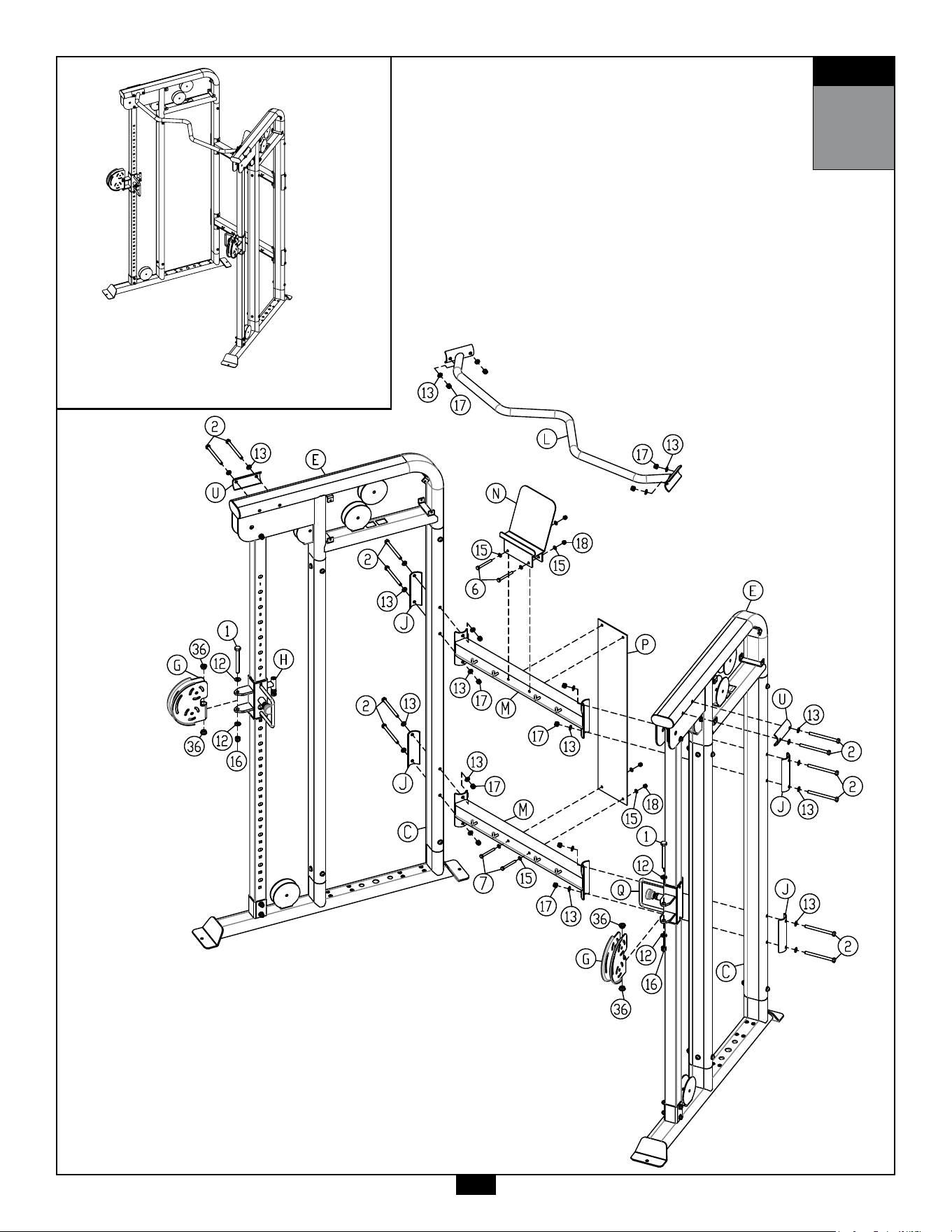
STEP
3
AboveshowsStep3assembledandcompleted.
19

20
STEP
4
Be careful to assemble all components
in the sequence they are presented.
NOTE:
Finger tighten all hardware in this step. DO NOT wrench tighten until instructed.
Some components may be pre-assembled. Nylon lock nuts will not fully screw onto
bolts, they must be wrench tightened to fully go on.
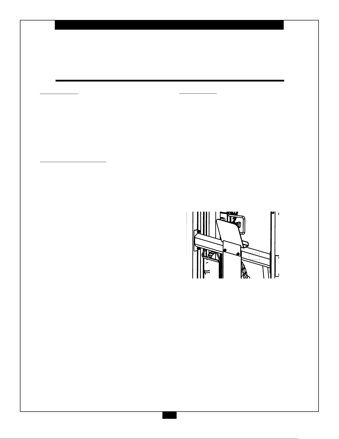
4A. InstallChromeGuideRods(F)intotheholesintheBaseFrame(A).
4B. InstallWeightRisers(R) & RubberDonuts(#31)andslidetothebottom
oftheGuideRods
Important Note: If 20pcs of weight plates are to be installed, do not
install Weight Risers (R)
4C. TiltGuideRods(F) awayfromtheBaseFrame(A) andinstall15pcs
ofweightplates.Becarefultoholdguiderodssteadilywheninstalling
weightplates.
4D. InstallTopPlate&SelectorRodAssembly(#30)ontotheGuideRods(F) .
4E. InstallWeightStackPin(#33)usingthekeyringendthroughthePulley
Bracket(K).
4F. InstallM12HexNut(#19),M12LockWasher(#20)andPulleyBracket(K)
ontotheTopPlate(#30).
4G. InstallShaftCollars(#37)ontotheGuideRods(F)
4H. SlideShaftCollars(#37)upwardsotheylocktheguiderodsintopositionby
tighteningtheM8x8mmSetScrews(#9).
4J. RepeattheSameSteps(4A to 4H)ontheothersideofthemachine.
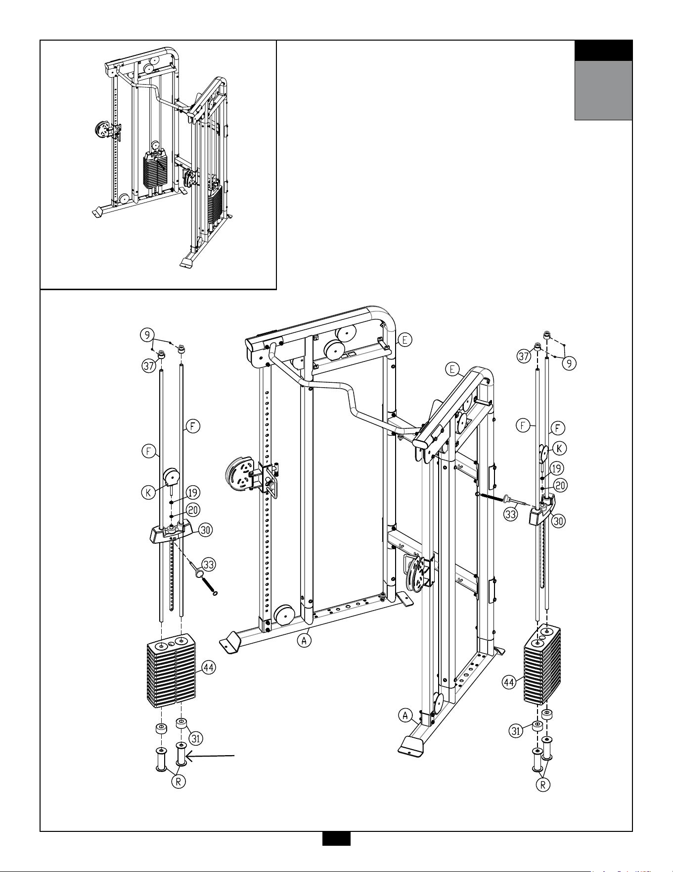
STEP
4
AboveshowsStep1assembledandcompleted.
21
Risersarenotrequired
with20pcsofWeight
plates

22
STEP
5
Be careful to assemble all components
in the sequence they are presented.
NOTE:
Wrench tighten ALL hardware at the end of STEP 5D. Some components may be
pre-assembled. Nylon lock nuts will not fully screw onto bolts, they must be wrench
tighten to fully go on.
5A. RouteCable(#29)whileinstallingTwoAluminumPulleys(#23),
One ø90mmPlasticPulleyandveø117mmPlasticPulley(#22)
ontherightsideofthemachineasshowninSTEP5drawingusing:
1 - (#3) M10x80mm Hex Head Bolt
7 - (#4) M10x50mm Hex Head Bolt
14 - (#13) M10 Washer
8 - (#17) M10 Nylon Lock Nut
2 - (#28) Pulley Spacer
5B. ScrewintwoM12HexNuts(#19)intoCableConnectorBolt(#25)
oftheCable(#29).
5C. AttachtheCableConnectorBolt(#25)oftheCable(#29)tothe
BackoftheRightSlidingHandle(#H)andsecuretheCable(#29)
bywrenchtighteningthetwoM12HexNuts(#19)
5D. RepeatthepreviousStep(5A-5C)ontheothersideofthemachine.
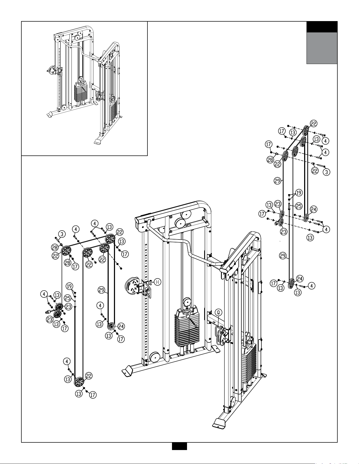
STEP
5
AboveshowsStep5assembledandcompleted.
23

24
STEP
6
Be careful to assemble all components
in the sequence they are presented.
NOTE:
Some components may be pre-assembled. Nylon lock nuts will not fully screw onto bolts,
they must be wrench tightened to fully go on.
6A. AttachLogoPlates(T & S)toTopFrames(E)using:
16 - (#8) M8x14mm Button Head Cap Screw
16 - (#15) M8 Washer
16 - (#21) M8 Lock Washer
6B. AttachSnapLinks(#41)toCables(29).
6C. AttachStrapHandles(#42),TricepRope(#39),LongStraight
Bar (#38) orLongStrap(#40)toSnapLinks(#41).
6D. StickExercisePlacard(#43)onPlacardPlate(P).
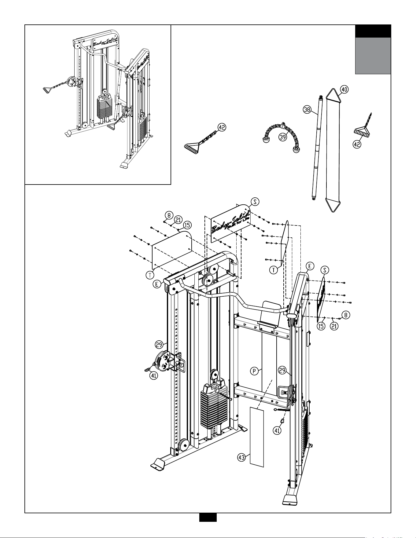
STEP
6
AboveshowsStep6assembledandcompleted.
25
45
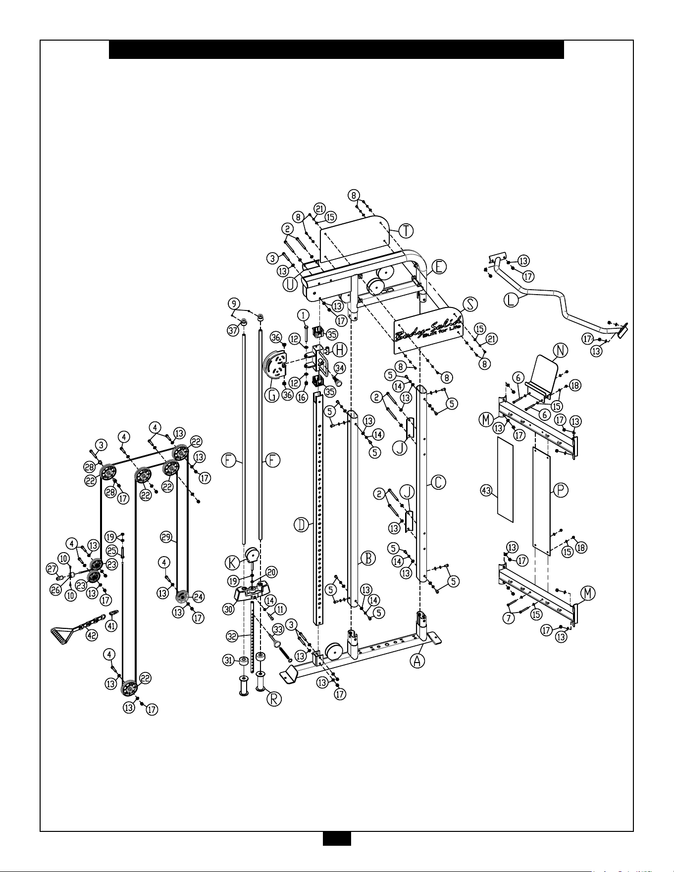
26
GFT100 Exploded View (1)
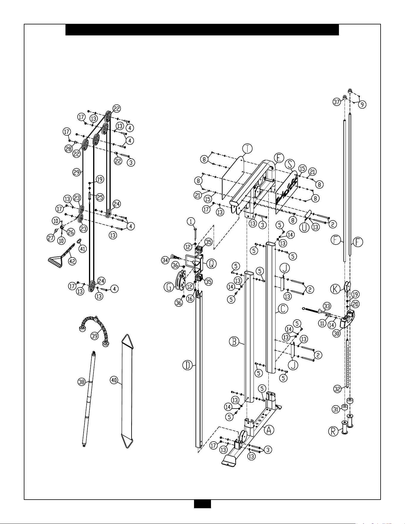
27
GFT100 Exploded View (2)

1900S.DesPlainesAve.
ForestPark,IL60130
Phone:(708)427-3555
Fax:(708)427-3556
Hours:M-F8:30-5:00CST
www.bodysolid.com
Copyright 2009. Body-Solid. All rights reserved. Body-Solid reserves the right to change design and specications when we feel it will improve the product.
Body-Solid machines maintain several patented and patent pending features and designs. All rights reserved on all design patents and utility patents.
PLEASE WRITE YOUR SERIAL NUMBER IN THE BOXES BELOW
S/N#
016149-��-��-����-����
GFT100