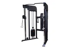
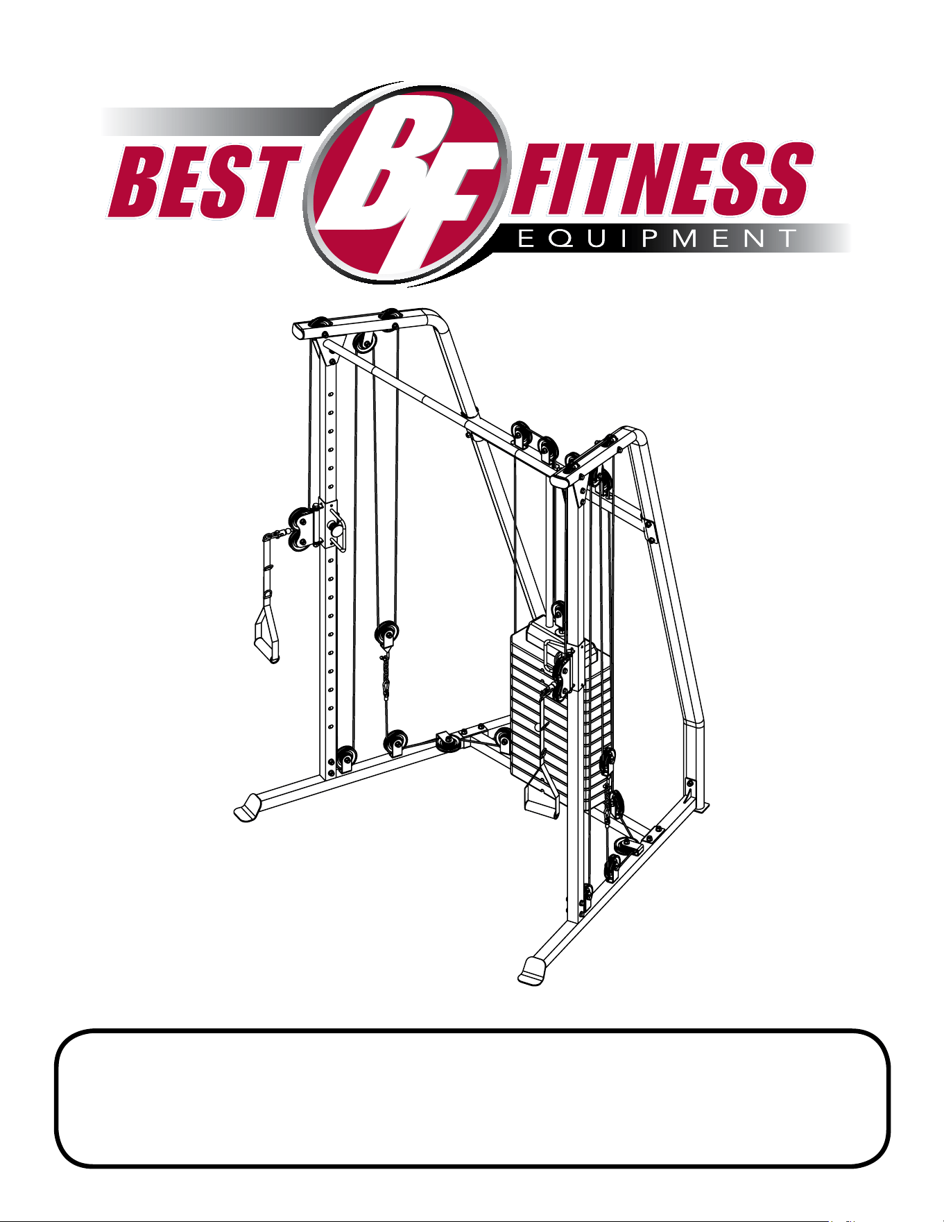
BFFT10B
OwneR’s Manual
v. 240821
2
waRning laBels
Adjust
Cable
Here
ALWAYS make sure pop
pin plunger is in place
and lock it by turning
clockwise until tight.
THERE IS A RISK ASSUMED BY INDIVIDUALS WHO USE THIS TYPE OF EQUIPMENT.
TO MINIMIZE RISK, YOU MUST FOLLOW THESE RULES:
Inspect equipment before each workout. Check that all nuts, bolts, screws and pop pins
are in place and fully tightened. Also, before use, check cables for sign of wear. Replace all
worn parts immediately. Never use machine if any parts are damaged or missing.
FAILURE TO FOLLOW THESE RULES MAY RESULT IN SERIOUS INJURY.
Keep clear of the cables and all moving parts when machine is in use.
Always make sure all Snap Links are closed when doing cable/pulley/strap exercises.
Exercise with care. Perform your exercises at a smooth moderate pace; never perform jerky
or uncoordinated movements that may cause injury.
It is recommended that you workout with a training partner.
Do not allow children or minors to play on or around this equipment.
If unsure of proper use of equipment, call your local Body-Solid distributor or the
Body-Solid customer service center at 1-800-556-3113.
WARNING: Consult your physician before starting your exercise program. For your own
safety, do not begin any exercise program without proper instruction.
THERE IS A RISK ASSUMED BY INDIVIDUALS WHO USE THIS TYPE OF EQUIPMENT.
TO MINIMIZE RISK, YOU MUST FOLLOW THESE RULES:
Inspect equipment before each workout. Check that all nuts, bolts, screws and pop pins
are in place and fully tightened. Also, before use, check cables for sign of wear. Replace all
worn parts immediately. Never use machine if any parts are damaged or missing.
FAILURE TO FOLLOW THESE RULES MAY RESULT IN SERIOUS INJURY.
Keep clear of the cables and all moving parts when machine is in use.
Always make sure all Snap Links are closed when doing cable/pulley/strap exercises.
Exercise with care. Perform your exercises at a smooth moderate pace; never perform jerky
or uncoordinated movements that may cause injury.
It is recommended that you workout with a training partner.
Do not allow children or minors to play on or around this equipment.
If unsure of proper use of equipment, call your local SteelFlex distributor or the SteelFlex
customer service center at 1-800-556-3113.
WARNING: Consult your physician before starting your exercise program. For your own
safety, do not begin any exercise program without proper instruction.
WARNING!
PINCH POINTS
Be alert! Keep hands
and fingers clear of
moving parts.
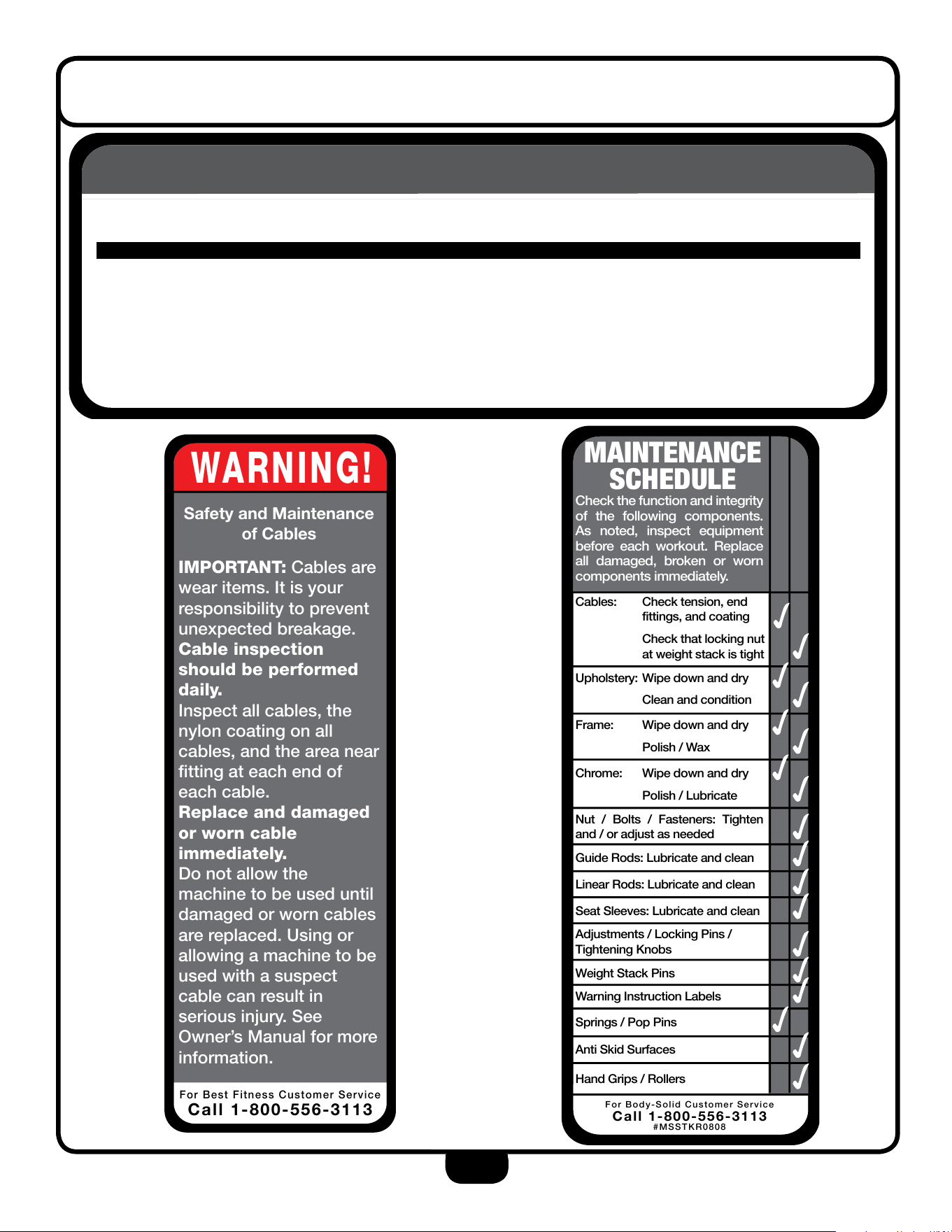
WARNING!
SafetyÊandÊMaintenance
ofÊCables
IMPORTANT:ÊCables are
wear items. It is your
responsibility to prevent
unexpected breakage.
Cable inspection
should be performed
daily.
Inspect all cables, the
nylon coating on all
cables, and the area near
fitting at each end of
each cable.
Replace and damaged
or worn cable
immediately.
Do not allow the
machine to be used until
damaged or worn cables
are replaced. Using or
allowing a machine to be
used with a suspect
cable can result in
serious injury. See
Owner’s Manual for more
information.
For Steelflex Customer Service
CallÊ1-800-556-3113
WARNING!
SafetyÊandÊMaintenance
ofÊCables
IMPORTANT:ÊCables are
wear items. It is your
responsibility to prevent
unexpected breakage.
Cable inspection
should be performed
daily.
Inspect all cables, the
nylon coating on all
cables, and the area near
fitting at each end of
each cable.
Replace and damaged
or worn cable
immediately.
Do not allow the
machine to be used until
damaged or worn cables
are replaced. Using or
allowing a machine to be
used with a suspect
cable can result in
serious injury. See
Owner’s Manual for more
information.
For Best Fitness Customer Service
CallÊ1-800-556-3113
WARNING!
SafetyÊandÊMaintenance
ofÊCables
IMPORTANT:ÊCables are
wear items. It is your
responsibility to prevent
unexpected breakage.
Cable inspection
should be performed
daily.
Inspect all cables, the
nylon coating on all
cables, and the area near
fitting at each end of
each cable.
Replace and damaged
or worn cable
immediately.
Do not allow the
machine to be used until
damaged or worn cables
are replaced. Using or
allowing a machine to be
used with a suspect
cable can result in
serious injury. See
Owner’s Manual for more
information.
For Body-Solid Customer Service
CallÊ1-800-556-3113
MAINTENANCE
SCHEDULE
Check the function and integrity
of the following components.
As noted, inspect equipment
before each workout. Replace
all damaged, broken or worn
components immediately.
Cables: Check tension, end
fittings, and coating
Check that locking nut
at weight stack is tight
Upholstery: Wipe down and dry
Clean and condition
Frame: Wipe down and dry
Polish / Wax
Chrome: Wipe down and dry
Polish / Lubricate
Nut / Bolts / Fasteners: Tighten
and / or adjust as needed
Guide Rods: Lubricate and clean
Linear Rods: Lubricate and clean
Seat Sleeves: Lubricate and clean
Weight Stack Pins
Warning Instruction Labels
Springs / Pop Pins
Anti Skid Surfaces
Hand Grips / Rollers
For Body-Solid Customer Service
CallÊ1-800-556-3113
#MSSTKR0808
Adjustments / Locking Pins /
Tightening Knobs
SteelFlex
THERE IS A RISK ASSUMED BY INDIVIDUALS WHO USE THIS TYPE OF EQUIPMENT.
TO MINIMIZE RISK, YOU MUST FOLLOW THESE RULES:
Inspect equipment before each workout. Check that all nuts, bolts, screws and pop pins
are in place and fully tightened. Also, before use, check cables for sign of wear. Replace all
worn parts immediately. Never use machine if any parts are damaged or missing.
FAILURE TO FOLLOW THESE RULES MAY RESULT IN SERIOUS INJURY.
Keep clear of the cables and all moving parts when machine is in use.
Always make sure all Snap Links are closed when doing cable/pulley/strap exercises.
Exercise with care. Perform your exercises at a smooth moderate pace; never perform jerky
or uncoordinated movements that may cause injury.
It is recommended that you workout with a training partner.
Do not allow children or minors to play on or around this equipment.
If unsure of proper use of equipment, call your local Best Fitness distributor or the Best
Fitness customer service center at 1-800-556-3113.
WARNING: Consult your physician before starting your exercise program. For your own
safety, do not begin any exercise program without proper instruction.
Best Fitness
Adjust
Cable
Here
ALWAYS make sure pop
pin plunger is in place
and lock it by turning
clockwise until tight.
THERE IS A RISK ASSUMED BY INDIVIDUALS WHO USE THIS TYPE OF EQUIPMENT.
TO MINIMIZE RISK, YOU MUST FOLLOW THESE RULES:
Inspect equipment before each workout. Check that all nuts, bolts, screws and pop pins
are in place and fully tightened. Also, before use, check cables for sign of wear. Replace all
worn parts immediately. Never use machine if any parts are damaged or missing.
FAILURE TO FOLLOW THESE RULES MAY RESULT IN SERIOUS INJURY.
Keep clear of the cables and all moving parts when machine is in use.
Always make sure all Snap Links are closed when doing cable/pulley/strap exercises.
Exercise with care. Perform your exercises at a smooth moderate pace; never perform jerky
or uncoordinated movements that may cause injury.
It is recommended that you workout with a training partner.
Do not allow children or minors to play on or around this equipment.
If unsure of proper use of equipment, call your local Body-Solid distributor or the
Body-Solid customer service center at 1-800-556-3113.
WARNING: Consult your physician before starting your exercise program. For your own
safety, do not begin any exercise program without proper instruction.
THERE IS A RISK ASSUMED BY INDIVIDUALS WHO USE THIS TYPE OF EQUIPMENT.
TO MINIMIZE RISK, YOU MUST FOLLOW THESE RULES:
Inspect equipment before each workout. Check that all nuts, bolts, screws and pop pins
are in place and fully tightened. Also, before use, check cables for sign of wear. Replace all
worn parts immediately. Never use machine if any parts are damaged or missing.
FAILURE TO FOLLOW THESE RULES MAY RESULT IN SERIOUS INJURY.
Keep clear of the cables and all moving parts when machine is in use.
Always make sure all Snap Links are closed when doing cable/pulley/strap exercises.
Exercise with care. Perform your exercises at a smooth moderate pace; never perform jerky
or uncoordinated movements that may cause injury.
It is recommended that you workout with a training partner.
Do not allow children or minors to play on or around this equipment.
If unsure of proper use of equipment, call your local SteelFlex distributor or the SteelFlex
customer service center at 1-800-556-3113.
WARNING: Consult your physician before starting your exercise program. For your own
safety, do not begin any exercise program without proper instruction.
WARNING!
PINCH POINTS
Be alert! Keep hands
and fingers clear of
moving parts.
WARNING!
SafetyÊandÊMaintenance
ofÊCables
IMPORTANT:ÊCables are
wear items. It is your
responsibility to prevent
unexpected breakage.
Cable inspection
should be performed
daily.
Inspect all cables, the
nylon coating on all
cables, and the area near
fitting at each end of
each cable.
Replace and damaged
or worn cable
immediately.
Do not allow the
machine to be used until
damaged or worn cables
are replaced. Using or
allowing a machine to be
used with a suspect
cable can result in
serious injury. See
Owner’s Manual for more
information.
For Steelflex Customer Service
CallÊ1-800-556-3113
WARNING!
SafetyÊandÊMaintenance
ofÊCables
IMPORTANT:ÊCables are
wear items. It is your
responsibility to prevent
unexpected breakage.
Cable inspection
should be performed
daily.
Inspect all cables, the
nylon coating on all
cables, and the area near
fitting at each end of
each cable.
Replace and damaged
or worn cable
immediately.
Do not allow the
machine to be used until
damaged or worn cables
are replaced. Using or
allowing a machine to be
used with a suspect
cable can result in
serious injury. See
Owner’s Manual for more
information.
For Best Fitness Customer Service
CallÊ1-800-556-3113
WARNING!
SafetyÊandÊMaintenance
ofÊCables
IMPORTANT:ÊCables are
wear items. It is your
responsibility to prevent
unexpected breakage.
Cable inspection
should be performed
daily.
Inspect all cables, the
nylon coating on all
cables, and the area near
fitting at each end of
each cable.
Replace and damaged
or worn cable
immediately.
Do not allow the
machine to be used until
damaged or worn cables
are replaced. Using or
allowing a machine to be
used with a suspect
cable can result in
serious injury. See
Owner’s Manual for more
information.
For Body-Solid Customer Service
CallÊ1-800-556-3113
MAINTENANCE
SCHEDULE
Check the function and integrity
of the following components.
As noted, inspect equipment
before each workout. Replace
all damaged, broken or worn
components immediately.
Cables: Check tension, end
fittings, and coating
Check that locking nut
at weight stack is tight
Upholstery: Wipe down and dry
Clean and condition
Frame: Wipe down and dry
Polish / Wax
Chrome: Wipe down and dry
Polish / Lubricate
Nut / Bolts / Fasteners: Tighten
and / or adjust as needed
Guide Rods: Lubricate and clean
Linear Rods: Lubricate and clean
Seat Sleeves: Lubricate and clean
Weight Stack Pins
Warning Instruction Labels
Springs / Pop Pins
Anti Skid Surfaces
Hand Grips / Rollers
For Body-Solid Customer Service
CallÊ1-800-556-3113
#MSSTKR0808
Adjustments / Locking Pins /
Tightening Knobs
SteelFlex
THERE IS A RISK ASSUMED BY INDIVIDUALS WHO USE THIS TYPE OF EQUIPMENT.
TO MINIMIZE RISK, YOU MUST FOLLOW THESE RULES:
Inspect equipment before each workout. Check that all nuts, bolts, screws and pop pins
are in place and fully tightened. Also, before use, check cables for sign of wear. Replace all
worn parts immediately. Never use machine if any parts are damaged or missing.
FAILURE TO FOLLOW THESE RULES MAY RESULT IN SERIOUS INJURY.
Keep clear of the cables and all moving parts when machine is in use.
Always make sure all Snap Links are closed when doing cable/pulley/strap exercises.
Exercise with care. Perform your exercises at a smooth moderate pace; never perform jerky
or uncoordinated movements that may cause injury.
It is recommended that you workout with a training partner.
Do not allow children or minors to play on or around this equipment.
If unsure of proper use of equipment, call your local Best Fitness distributor or the Best
Fitness customer service center at 1-800-556-3113.
WARNING: Consult your physician before starting your exercise program. For your own
safety, do not begin any exercise program without proper instruction.
Best Fitness

3
TaBle OF cOnTenTs
saFeTY insTRucTiOns..............................
PRePaRaTiOn...........................................
HaRDwaRe lisT.......................................
HaRDwaRe illusTRaTiOn........................
PaRT lisT / illusTRaTiOn.......................
asseMBlY insTRucTiOns.........................
eXPlODeD View.......................................
cOnTacT Page.........................................
Page 4
Page 5
Page 6
Page 8
Page 10
Page 12
Page 28
Page 30

4
iMPORTanT saFeTY insTRucTiOns
Unpacking the Equipment
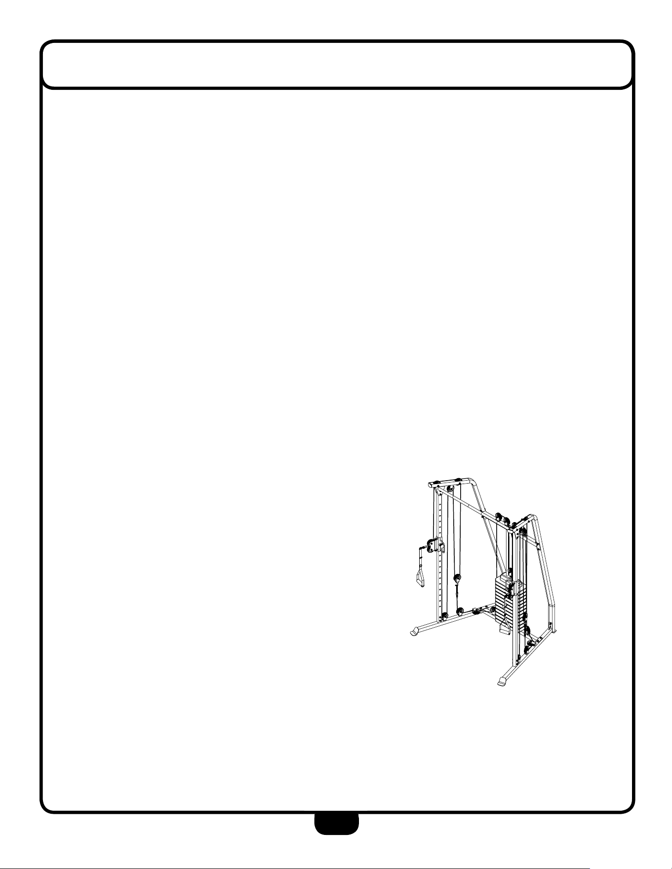
The BFFT10B is carefully tested and inspected before
shipment. We have shipped the unit in two boxes that
require assembly. Ask for assistance during the
assembly process.
Carefully unpack the boxes and lay the pieces on
the oor near the area where you plan to use the
equipment.
When using exercise equipment, you
should always take basic precautions,
including the following:
• Read all instructions before using the BFFT10B. These
instructions are written to ensure your safety and to
protect the unit.
• Do not remove any safety labels fromt the
machine.
• Do not allow children on or near the equipment.
• Use the equipment only for its intended purpose as
described in this guide. Do not use accessory
attachments that are not recommended by the
manufacturer. Such attachments might cause injuries.
• Wear proper exercise clothing and shoes for your
workout, no loose clothing.
• Keep hands, limbs, loose clothing, and long hair well
out of the way of all moving parts.
• Use care when getting on or off the unit.
• Do not overexert yourself or work to exhaustion.
• If you feel any pain or abnormal symptoms, stop your
workout immediately and consult your physician.
• Never operate unit when it has been dropped or
damaged. Return the equipment to a service center for
examination and repair.
• Never drop or insert objects into any opening in the
equipment.
• Always check the unit before each use. Make sure
that all fasteners are secure and in good working
condition.
• Do not use the equipment outdoors or near water.
Personal Safety During Assembly
• It is strongly recommended that a qualified dealer
assemble the equipment. Assistance is required.
• Before beginning assembly, please take the time to
read the instructions thoroughly.
• Read each step in the assembly instructions and
follow the steps in sequence. Do not skip ahead. If
you skip ahead, you may learn later that you have to
disassemble components and that you may have
damaged the equipment.
• Assemble and operate the BFFT10B on a solid, level
surface. Locate the unit a few feet from the walls or
furniture to provide easy access.
The BFFT10B is designed for your enjoyment. By
following these precautions and using common
sense, you will have many safe and pleasurable hours
of healthful exercise with your Best Fitness BFFT10B.
After assembly, you should check all functions to
ensure correct operation. If you experience problems,
rst recheck the assembly instructions to locate any
possible errors made during assembly. If you are unable
to correct the problem, call the dealer from whom
you purchased the machine or call 1-800-556-3113
for the dealer nearest you.
Obtaining Service
Please use this Owner’s Manual to make sure that all
parts have been included in your shipment. When
ordering parts, you must use the part number and
description from this Owner’s Manual. Use only
Best Fitness replacement parts when servicing this
machine. Failure to do so will void your warranty and
could result in personal injury.
For information about product operation or service,
go to www.besttness.com or contact an authorized
Best Fitness dealer or a Best Fitness factory-authorized
service company or contact Best Fitness customer
service at one of the following:
Toll Free: 1-800-556-3113
Phone: 1-708-427-3555
Fax: 1-708-427-3556
Hours: M-F 8:30-5:00 CST
E-Mail: [email protected]
Or write to: Best Fitness
Service Department
1900 S. Des Plaines Ave.
Forest Park, IL 60130 USA
Retain this Owner’s Manual for future
reference. Part numbers are required when
ordering parts.
5
PRePaRaTiOn
Assembly Tips
Read all “Notes” on each page before beginning each
step.
While you may be able to assemble the BFFT10B using
the
illustrations only, important safety notes and other tips are
included in the text.
Some pieces may have extra holes that you will not use.
Use only those holes indicated in the instructions and
illustrations.
NOTE: With so many assembled parts, proper alignment
and adjustment is critical. While tightening the
nuts and bolts, be sure to leave room for
adjustments.
NOTE: The bottles that are marked “Poison” is your
touch up pain. Keep away from children.
CAUTION: Obtain assistance! If you feel like you can’t
assemble the BFFT10B by yourself then do not attempt
to do so as this could result in injury. Review installation
requirements before proceeding with the following steps.
Required Tools
The basic tools that you must obtain before assembling
the
BFFT10B include but are not limit to:
• Metric Wrench Set
• Adjustable Wrench
• Metric Allen Key Set
• Screwdriver (Standard/Phillips)\
Installation Requirements
Follow the installation requirements when assembling the
BFFT10B.
Set up the BFFT10
B on a solid, flat surface. A smooth flat
surface under the machine helps keep it level.
Provide ample space around the machine. Open space
around the machine will allow for easier access.
For aesthetic purposes, insert all bolts in the same
direction unless specied (in text or illustrations) to do so
otherwise.
Leave room for adjustements. Tighten fasteners such as
bolts, nuts, and screws so the unit is stable, but leave
somewhat loose for adjustments. Do not fully tighten
fasteners until instructed in the assembly steps to do so.
Fill out and mail the warranty card.
Ordering Replacement Parts
If you need to order replacement parts please be prepared
to provide the following information when contacting us so
that we can assist you better.
1. Model Number
2. Place of Purchase
3. Serial Number (S/N)
4. Part# and Description
YOUR S/N # CAN
BE FOUND HERE
↑
↑
↑

PART# SIZE DESCRIPTION QUANTITY
1
2
3
4
5
6
7
8
9
10
11
12
13
14
15
16
17
25X12.5X10mm
25X10.5X32mm
7350mm
6740mm
90mm
45X45mm
40X80mm
25mm
56X96mm
86X45mm
PULL PIN
BUSHING
BUSHING
CABLE
CABLE
STEEL CHAIN
SNAP LINK
PULLEY
PLASTIC PLATE
SQUARE END CAP
OVAL END CAP
END CAP
SILICON NUBE
EVA PAD
EVA PAD
RUBBER DONUT
HANDLE STRAP
2 PCS.
4 PCS.
8 PCS.
1 PCS.
2 PCS.
2 PCS.
4 PCS.
25 PCS.
1 PCS.
2 PCS.
2 PCS.
1 PCS.
16 PCS.
2 PCS.
2 PCS.
2 PCS.
2 PCS.
11
HaRDwaRe lisT
6

PART# SIZE DESCRIPTION QUANTITY
18
19
20
21
22
23
24
25
26
27
28
29
30
31
32
33
34
35
36
37
38
41
HaRDwaRe lisT
7
M12X175mm
M10X40mm
M10X60mm
M10X70mm
M10X100mm
M6X8mm
M8X10mm
M6
M12
M10
M12
M10
M12
38X12X2mm
M10X65mm
HEX HEAD BOLT
HEX HEAD BOLT
HEX HEAD BOLT
HEX HEAD BOLT
HEX HEAD BOLT
SOCKET SCREW
ACORN CAPNUT
WASHER
WASHER
NYLON LOCK NUT
NYLON LOCK NUT
TOP STACK
BOTTOM STACK
WEIGHT PLATE PIN
PUSHNUT
PIVOT AXLE
NUT
WASHER
CLEVIS PIN
RETAINING RING
HEX HEAD BOLT
2 PCS.
21 PCS.
12 PCS.
4 PCS.
4 PCS.
3 PCS.
6 PCS.
2 PCS.
4 PCS.
88 PCS.
2 PCS.
43 PCS.
1 PCS.
12 PCS.
1 PCS.
1 PCS.
1 PCS.
1 PCS.
1 PCS.
2 PCS.
2 PCS.
4 PCS
8
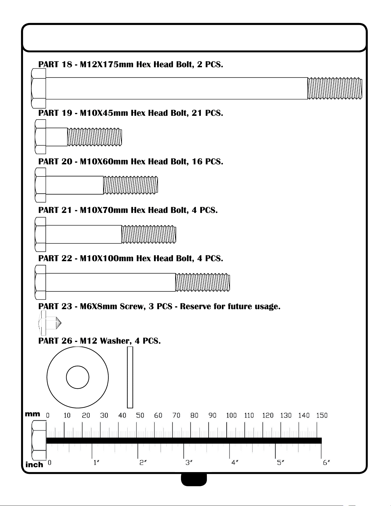
HaRDwaRe illusTRaTiOn
PART 18 - M12X175mm Hex Head Bolt, 2 PCS.
PART 19 - M10X45mm Hex Head Bolt, 21 PCS.
PART 20 - M10X60mm Hex Head Bolt, 16 PCS.
PART 21 - M10X70mm Hex Head Bolt, 4 PCS.
PART 22 - M10X100mm Hex Head Bolt, 4 PCS.
PART 23 - M6X8mm Screw, 3 PCS - Reserve for future usage.
PART 26 - M12 Washer, 4 PCS.
59
HARDWARE
(shown in actual size)
mm
inch
G 5 S H A R D W A R E
( s h o w n I n a c t u a l s i z e )
KEY #46 HEX HEAD BOLT M10X185L PARTIAL THREAD QTY.2
KEY #53 HEX HEAD BOLT M10X80L
PARTIAL THREAD QTY.2
KEY #48 HEX HEAD BOLT M10X65L
PARTIAL THREAD QTY.5
KEY #49 HEX HEAD BOLT M10X45L
PARTIAL THREAD QTY.14
mm
inch
0
60
10
30
50
40
20
60 130120110
100
90
8070
140
150
10
1"
6"
4"
3"
5"
2"
0
0
KEY #38 HEX HEAD BOLT 3/8"X 7/8"L
FULL THREAD QTY.1
KEY #50 HEX HEAD BOLT M10X25L
PARTIAL THREAD QTY.2
KEY #69 SPRING WASHER M12
QTY.1
KEY #58 WASHER M10 X Ø27
QTY.44
KEY #109 WASHER M10 X Ø19
QTY.6
KEY #105 WASHER M8 X Ø24
QTY.2
KEY #63 HEX HEAD BOLT M10X70L
PARTIAL THREAD QTY.1
87
KEY #57 WASHER M12 X Ø34
QTY.36
9
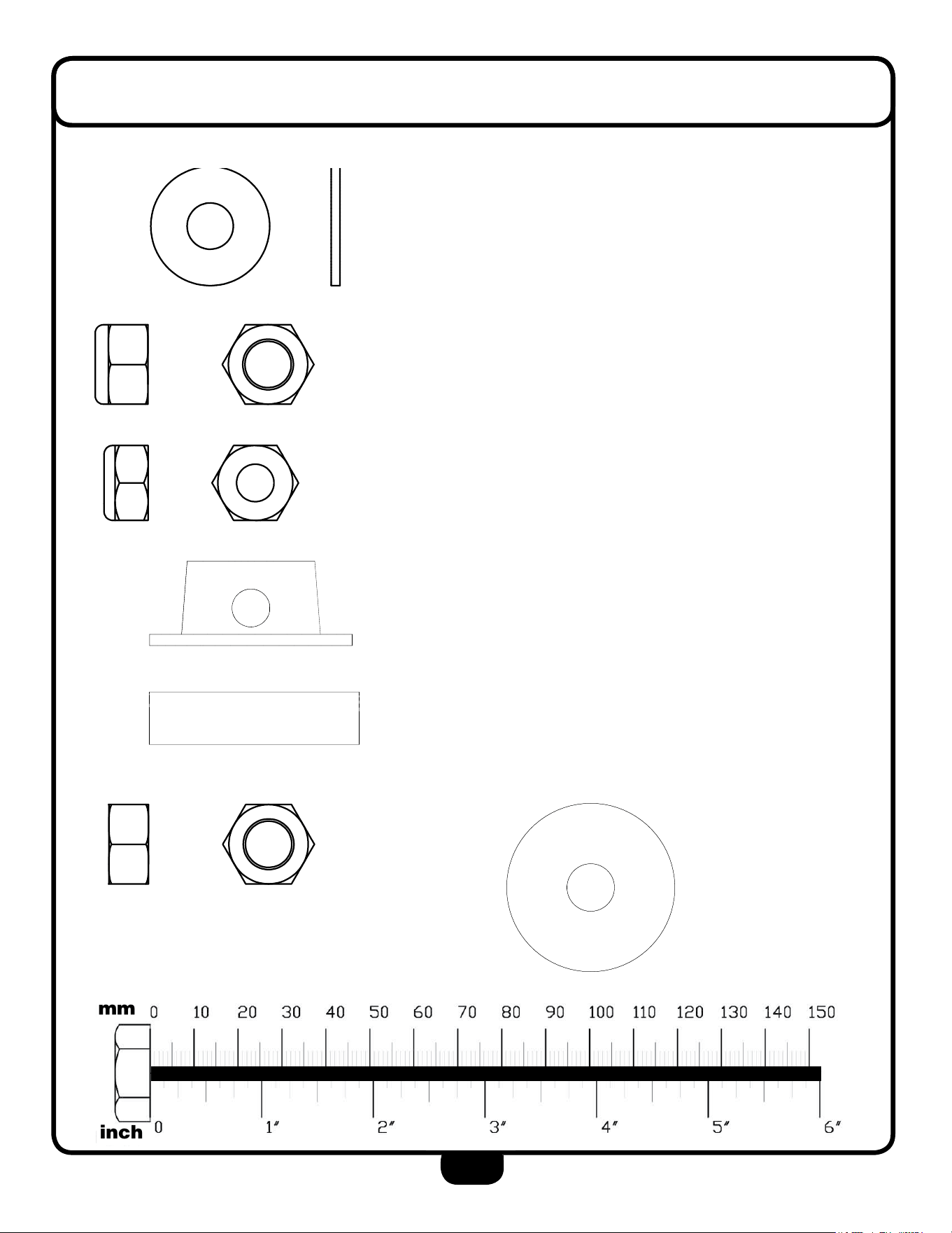
HaRDwaRe illusTRaTiOn
PaRT 27 - M10 washer, 88 Pcs.
PaRT 28 - M12 nylon lock nut, 2 Pcs.
PaRT 29 - M10 nylon lock nut, 43 Pcs.
PaRT 33 - Push nut, 1 Pcs.
PaRT 34 - Pivot axle, 1 Pcs.
PaRT 35 - M12 nut, 1 Pcs. PaRT 36 - M12 large washer, 1 Pcs.
59
HARDWARE
(shown in actual size)
mm
inch
G 5 S H A R D W A R E
( s h o w n I n a c t u a l s i z e )
KEY #46 HEX HEAD BOLT M10X185L PARTIAL THREAD QTY.2
KEY #53 HEX HEAD BOLT M10X80L
PARTIAL THREAD QTY.2
KEY #48 HEX HEAD BOLT M10X65L
PARTIAL THREAD QTY.5
KEY #49 HEX HEAD BOLT M10X45L
PARTIAL THREAD QTY.14
mm
inch
0
60
10
30
50
40
20
60 130120110
100
90
8070
140
150
10
1"
6"
4"
3"
5"
2"
0
0
KEY #38 HEX HEAD BOLT 3/8"X 7/8"L
FULL THREAD QTY.1
KEY #50 HEX HEAD BOLT M10X25L
PARTIAL THREAD QTY.2
KEY #69 SPRING WASHER M12
QTY.1
KEY #58 WASHER M10 X Ø27
QTY.44
KEY #109 WASHER M10 X Ø19
QTY.6
KEY #105 WASHER M8 X Ø24
QTY.2
KEY #63 HEX HEAD BOLT M10X70L
PARTIAL THREAD QTY.1
87
KEY #57 WASHER M12 X Ø34
QTY.36
4574
Hardware
(To Scale)
G 3 S H A R D W A R E
( s h o w n i n a c t u a l s i z e )
KEY #50 NYLON LOCK NUT M12
QTY. 2
KEY #54 WASHER M12 QTY. 2
KEY #51 NYLON LOCK NUT M10
QTY. 33
KEY #55 WASHER M10 QTY. 24
KEY #57 WASHER M10(Ø19) QTY. 5
KEY #59 SPRING LOCK WASHER
5/16" QTY. 4
KEY #58 WASHER 5/16” QTY. 4
mm
inch
0
60
10
30
50
40
20
60 130120
110
10090
8070
140
150
10
1"
6"
4"
3"
5"
2"
0
0
80
Part# 50 M12 Nylon Lock Nut Qty. 2
Part# 51 M10 Nylon Lock Nut Qty. 33
Part# 57 M10 (OD 19) Washer Qty. 5
Part# 54 M12 Washer Qty. 2
Part# 59 5/16” Spring Lock Washer Qty. 4
Part# 55 M10 Washer Qty. 24
Part# 58 5/16” Washer Qty. 4
10
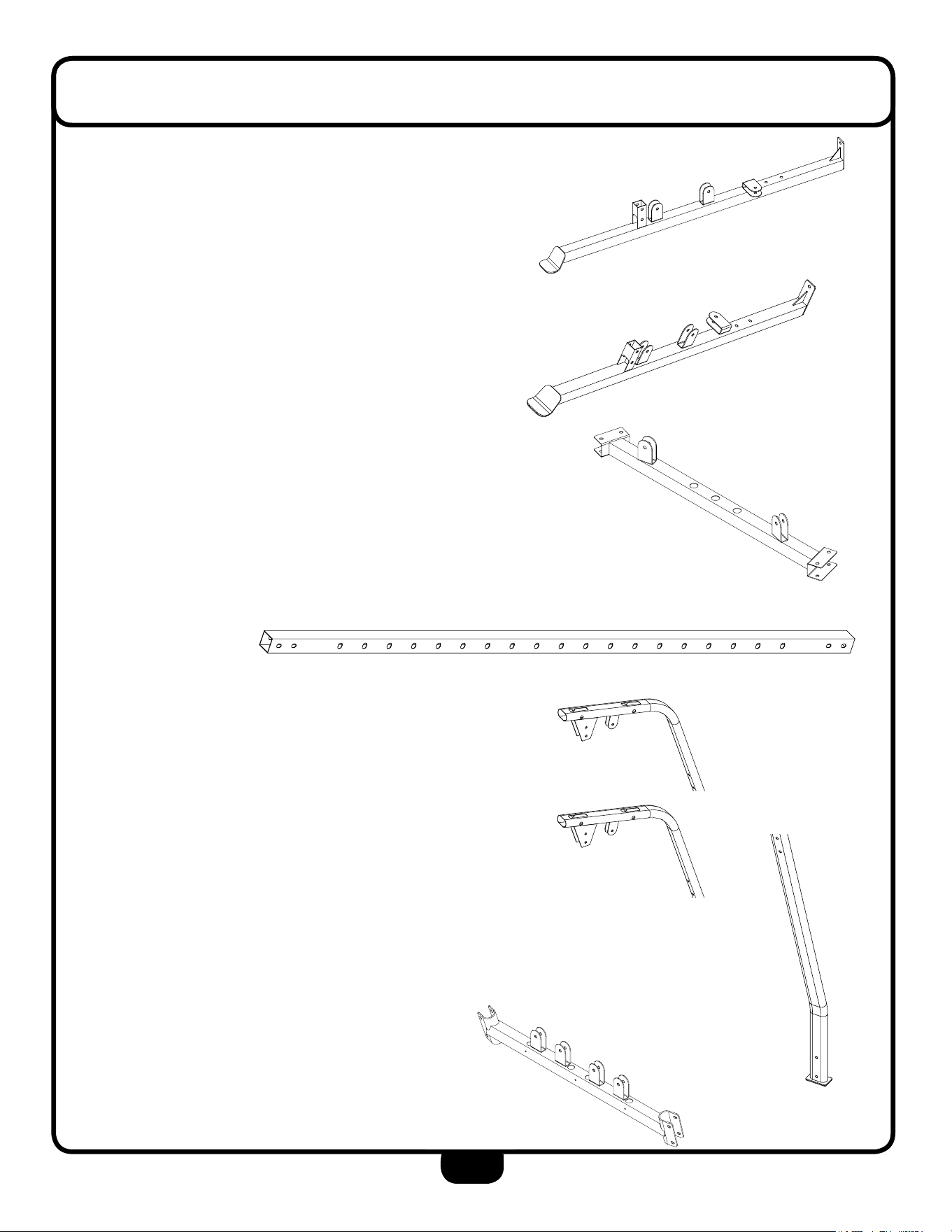
PaRT lisT
PaRT a - leFT lOweR BeaM, 1 Pcs.
PaRT B - RigHT lOweR BeaM, 1 Pcs.
PaRT c - Base FRaMe, 1 Pcs.
PaRT D - selecTing uPRigHT, 2 Pcs.
PaRT e - leFT uPPeR uPRigHT, 1 Pcs.
PaRT P - RigHT uPPeR uPRigHT, 1 Pcs.
PaRT F - lOweR uPRigHT, 2 Pcs.
PaRT g - suPPORT BeaM, 1 Pcs.
← e
← F
← P
11
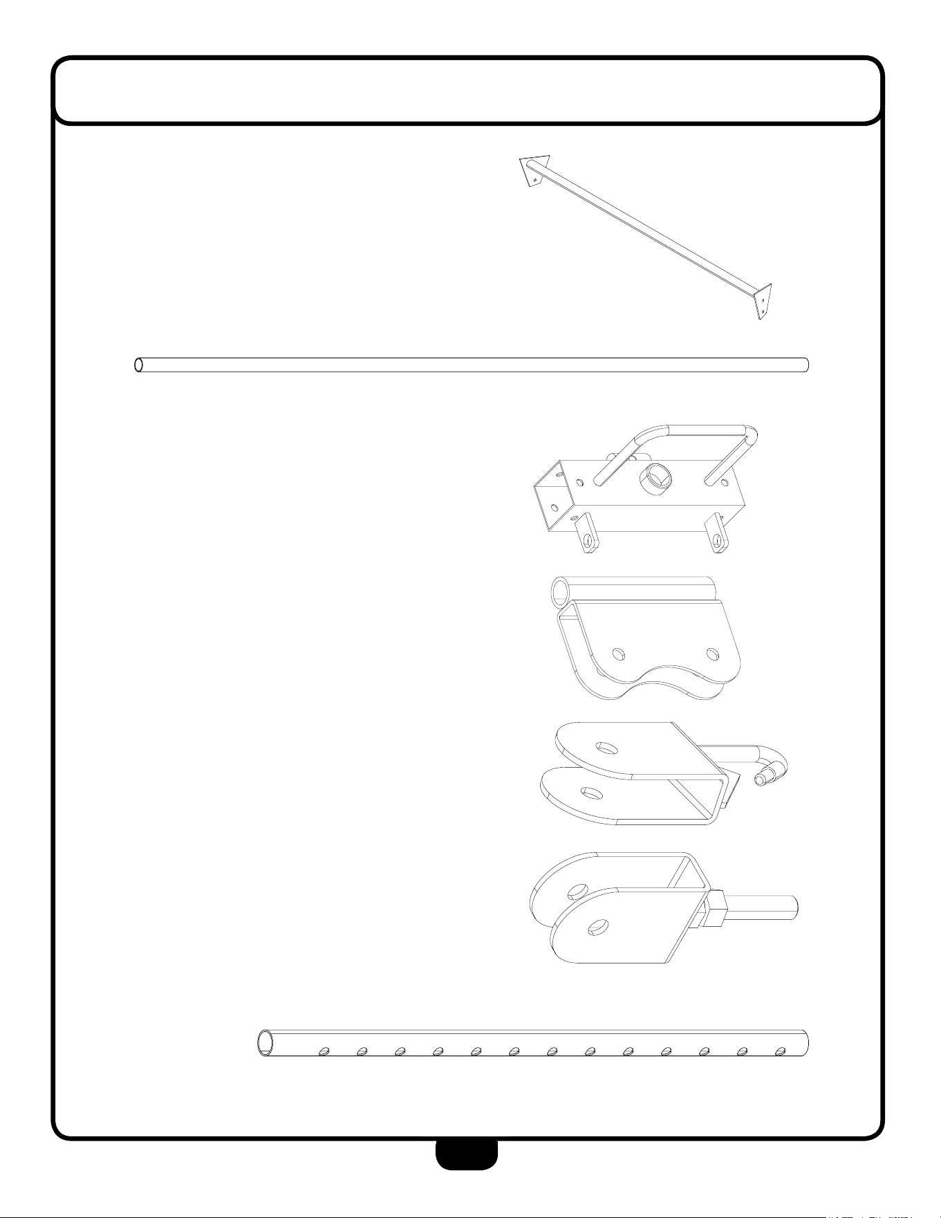
PaRT lisT
PaRT H - laT BaR, 1 Pcs.
PaRT i - guiDe ROD, 2 Pcs.
PaRT J - HanDle asseMBlY, 2 Pcs.
PaRT K - DOuBle PulleY, 2 Pcs.
PaRT l - PulleY HOlDeR, 2 Pcs.
PaRT M - single PulleY, 1 Pcs.
PaRT n - selecTOR ROD, 1 Pcs.
12
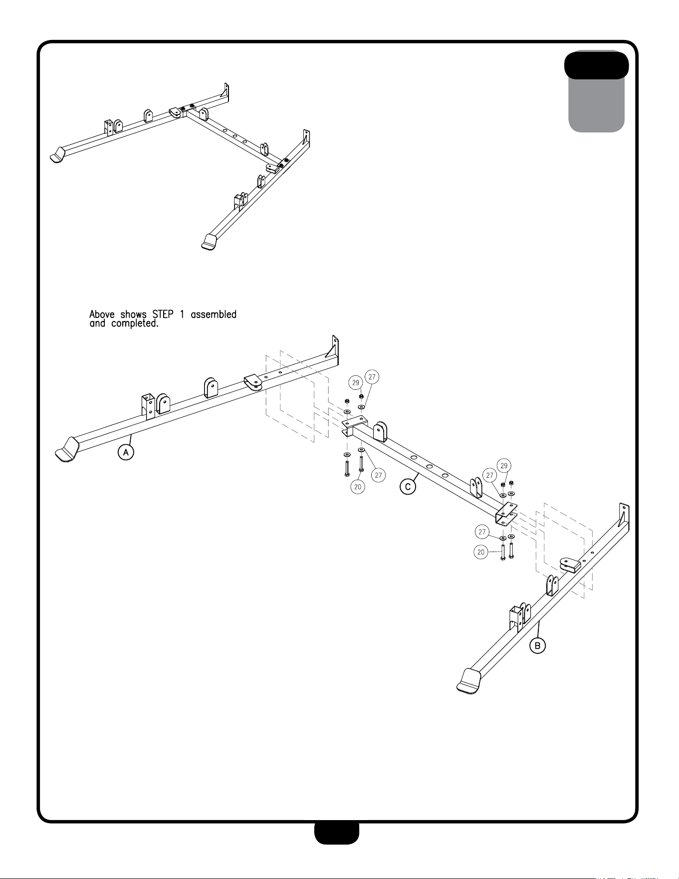
Be careful to assemble all components
in the sequence they are presented.
1A. Attach Left Lower Beam (A) to Base Frame (C) using:
2 - (#20) M10X62mm Hex Head Bolt
4 - (#27) M10 Washer
2 - (#29) M10 Nylon Lock Nut
1B. Attach Right Lower Beam (B) to Base Frame (C)
using:
2 - (#20) M10X62mm Hex Head Bolt
4 - (#27) M10 Washer
2 - (#29) M10 Nylon Lock Nut
Note: Bolt #20, M10X62mm, in this step needs to be bottom up as
shown in the picture to the right.
sTeP
1
nOTe:
Finger tighten all hardware first in this step. wrench tighten bolts at
the end of this step, some components may be pre-assembled.
nylon lock nuts will not fully screw onto bolts, must wrench tighten.
13
sTeP
1

Be careful to assemble all components
in the sequence they are presented.
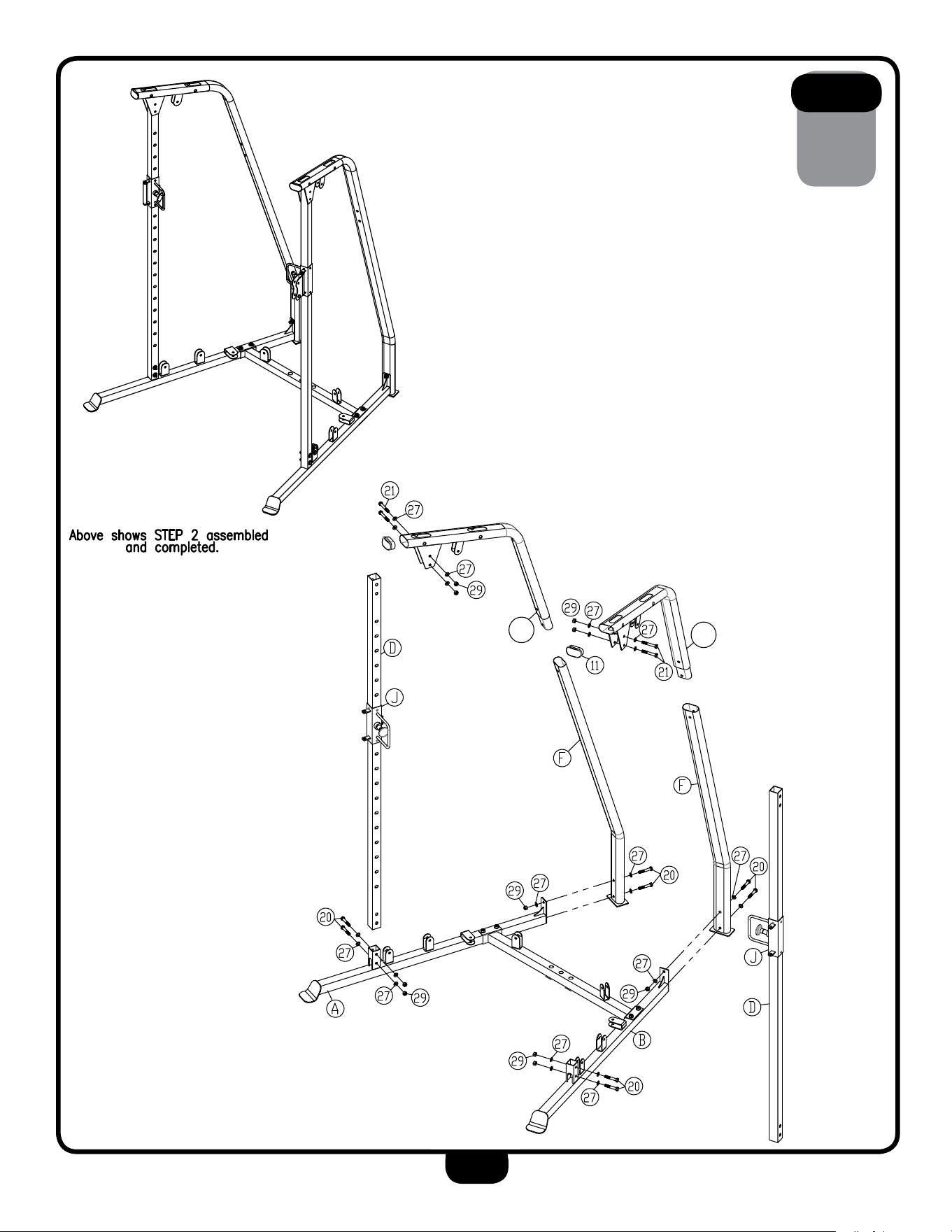
sTeP
2
14
2A. Attach Chrome Uprights (D) to Lower Beams (A & B) using:
4 - (#20) M10X60mm Hex Head Bolt
8 - (#27) M10 Washer
4 - (#29) M10 Nylon Lock Nut
2C. Slide a Handle Assembly (J) onto each Selecting
Upright (D).
2D. Secure Lower Uprights (F) to Lower Beams (A & B) using:
4 - (#20) M10X60mm Hex Head Bolt
6 - (#27) M10 Washer
2 - (#29) M10 Nylon Lock Nut
2E. Attach Upper Uprights (E & P) into Lower Uprights (F) and at-
tach
Upper Uprights (E & P) to Chrome Uprights using:
4 - (#21) M10X70mm Hex Head Bolt
8 - (#27) M10 Washer
4 - (#29) M10 Nylon Lock Nut
2F. Insert end caps into each top end opening of Upright (E & P)
using:
2 - (#11) 40X80mm Oval End Cap
nOTe:
Finger tighten all hardware in this step. DO nOT wrench tighten
until the end of step 4, some components may be pre-assembled.
nylon lock nuts will not fully screw onto bolts, must wrench tighten.
sTeP
2
15
a
P
E

Be careful to assemble all components
in the sequence they are presented.
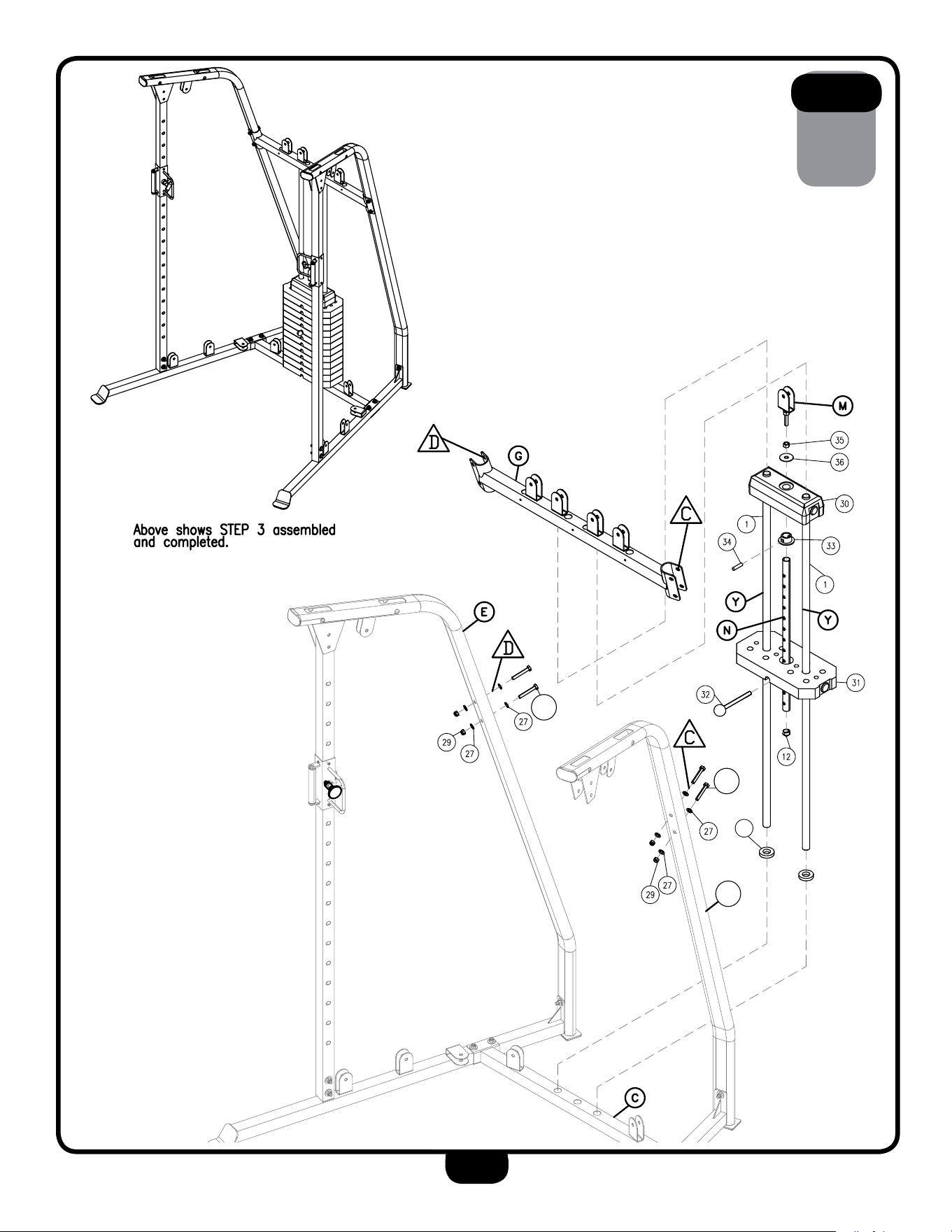
sTeP
3
16
3A. Insert each Guide Rod (Y) thru one 86X45mm Rubber Donut (#16)
and into a circular opening of Base Frame (C).
3B. Insert all Weight Plates (#31) onto Guide Rods (Y).
3C. Insert Push Nut (#33) onto Selector Rod (N) and secure by
sliding Pivot Axle (#34) thru the Push Nut (#33) and the rst
opening of Selector Rod (N).
3D. Take the key ring end of the Weight Plate Pin (#32) and slide
it onto the the threaded shaft of Single Pulley (M) and secure
by screwing on a M12 Nut (#35).
3E. While holding the Selector Rod, place the bottom end of
Top Stack (#30) onto the Push Nut and the Pivot Axle.
3F. Secure the Top Stack to the Selector Rod by sliding a M12
Large Washer (#36) onto the threaded shaft of Single Pulley (M)
and screwing Single Pulley (M) into the internal threads of
Selector Rod (M). Slide Top Stack onto Guide Rods (Y).
Note: Tighten the M12 Nut (#35) to better secure Single Pulley (M).
3G. Insert Each Guide Rod (Y) into a circular opening of
Support Beam (G), and attach Support Beam (G) to both Left
and Right Upper Upright (E & P) using:
4 - (#41) M10X65mm Hex Head Bolt
8 - (#27) M10 Washer
4 - (#29) M10 Nylon Lock Nut
nOTe:
Finger tighten all hardware in this step. DO nOT wrench tighten
until the end of step 4, some components may be pre-assembled.
nylon lock nuts will not fully screw onto bolts, must wrench tighten.
sTeP
3
17
16
a
P
a
41
a
41

Be careful to assemble all components
in the sequence they are presented.
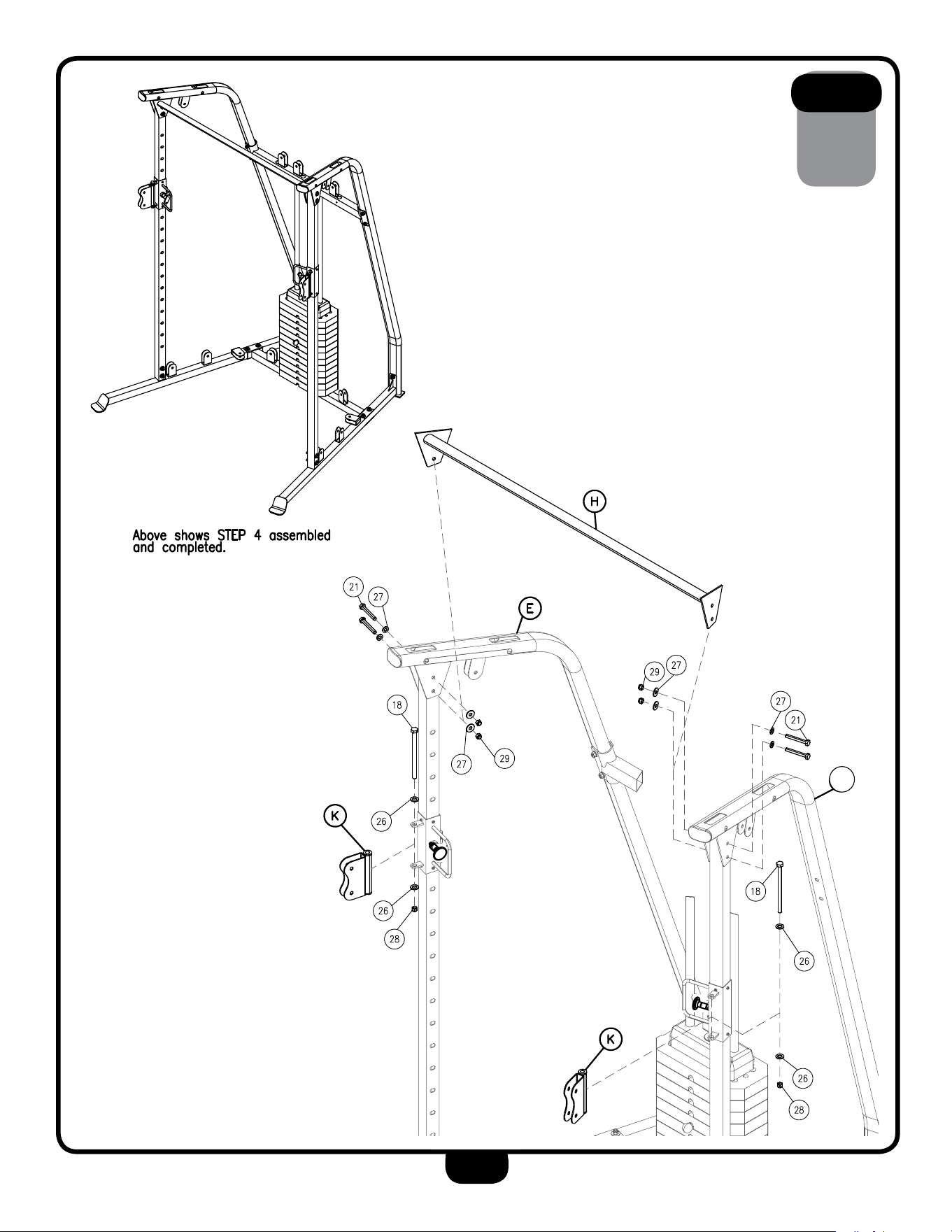
sTeP
4
18
4A. Attach Lat Bar (H) to Left Upright (E) and Right Upright (P)
using:
4 - (#21) M10X72mm Hex Head Bolt
8 - (#27) M10 Washer
4 - (#29) M10 Nylon Lock Nut
4B. Attach a Double Pulley (K) to a Handle Assembly (J) on both
the left and right side using:
2 - (#18) M12X175mm Hex Head Bolt
4 - (#26) M12 Washer
2 - (#28) M12 Nylon Lock Nut
Note: Do not tighten down bolts to hard, make sure that the
Double Pulley is able to swivel.
nOTe:
Finger tighten all hardware first. wrench tighten all bolts at the end
of this step, some components may be pre-assembled.
nylon lock nuts will not fully screw onto bolts, must wrench tighten.
sTeP
4
19
a
P
Be careful to assemble all components
in the sequence they are presented.
sTeP
5
20
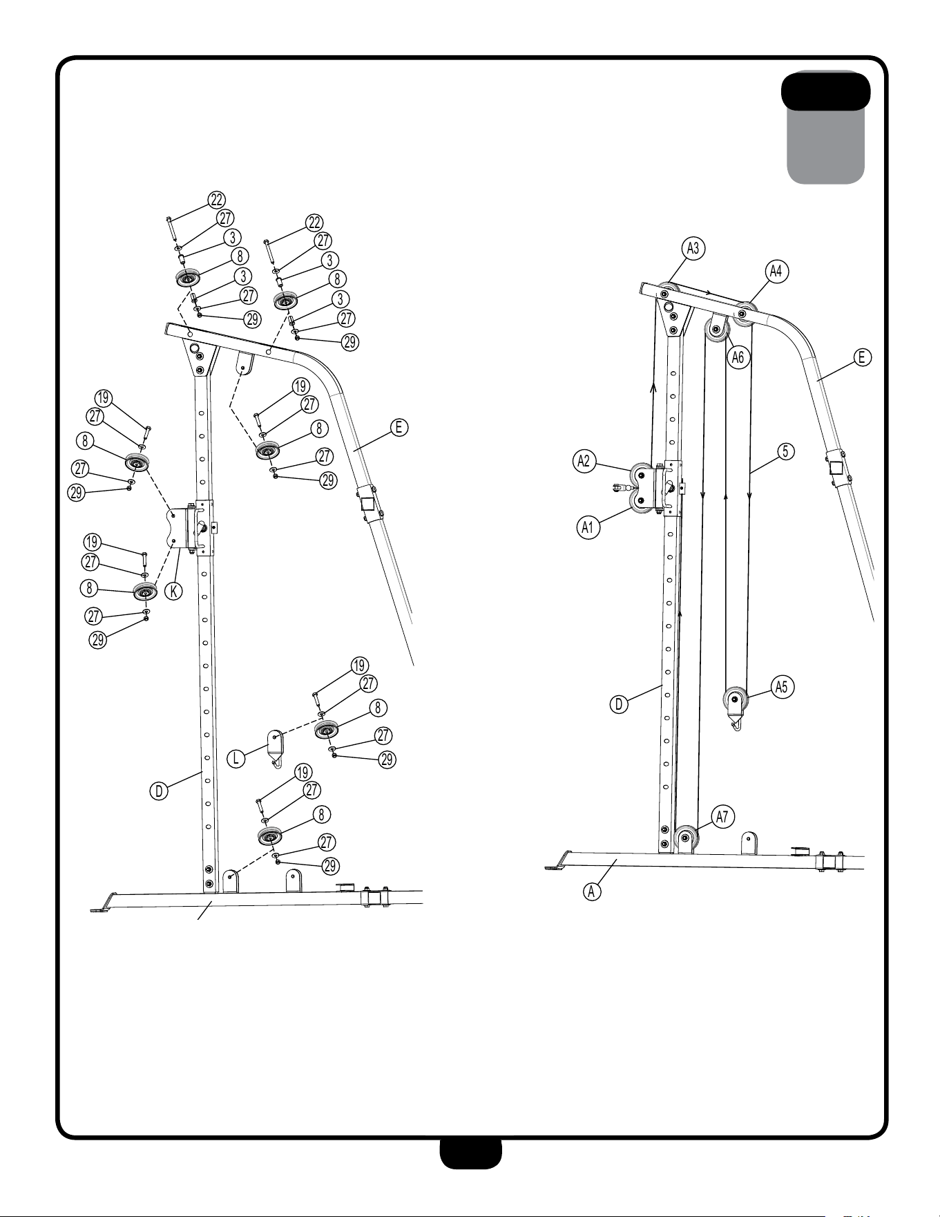
5A. Attach two Pulleys to Double Pulley (K) using:
2 - (#19) M10X42mm Hex Head Bolt
4 - (#27) M10 Washer
2 - (#8) 90mm Pulley
2 - (#29) M10 Nylon Lock Nut
5B. Attach a Pulley to Pulley Holder (L), the inside holder of Left
Upright (E), and the front holder of Left Lower Beam (A) using:
3 - (#19) M10X42mm Hex Head Bolt
6 - (#27) M10 Washer
3 - (#8) 90mm Pulley
3 - (#29) M10 Nylon Lock Nut
5C. Attach a Pulley to the front and rear top openings of Left
Upright (E) using:
2 - (#22) M10X102mm Hex Head Bolt
4 - (#27) M10 Washer
4 - (#3) 25X10.5X32mm Bushing
2 - (#8) 90mm Pulley
2 - (#29) M10 Nylon Lock Nut
5D. Cable Routing: Use a 6740mm Cable (#5). First, route the non-clip
end of the cable over pulley A1 and under then around pulley A2.
Second, route the cable up and over pulley A3 then over and down
pulley A4. Third, route the cable down and around pulley A5 then up
and over pulley A6. Lastly, route the cable down and around pulley
A7 and back up into the cable holder on Handle Assembly (J).
Secure the cable just enough to hold by tightening the socket set
screw (#24) that is pre-installed on Handle Assembly (J).
nOTe:
Finger tighten all hardware first. DO nOT wrench tighten until the
end of step 8, some components may be pre-assembled.
nylon lock nuts will not fully screw onto bolts, must wrench tighten.
sTeP
5
21
A1
A2
A3
A4
A6 E
5
A5
A7
D
A
29
27
3
8
3
27
22
29
27
3
8
3
27
22
29
27
8
27
19
29
27
8
27
19
29
27
8
27
19
19
27
8
27
29
19
27
8
27
29
L
E
D
K

Be careful to assemble all components
in the sequence they are presented.
sTeP
6
22
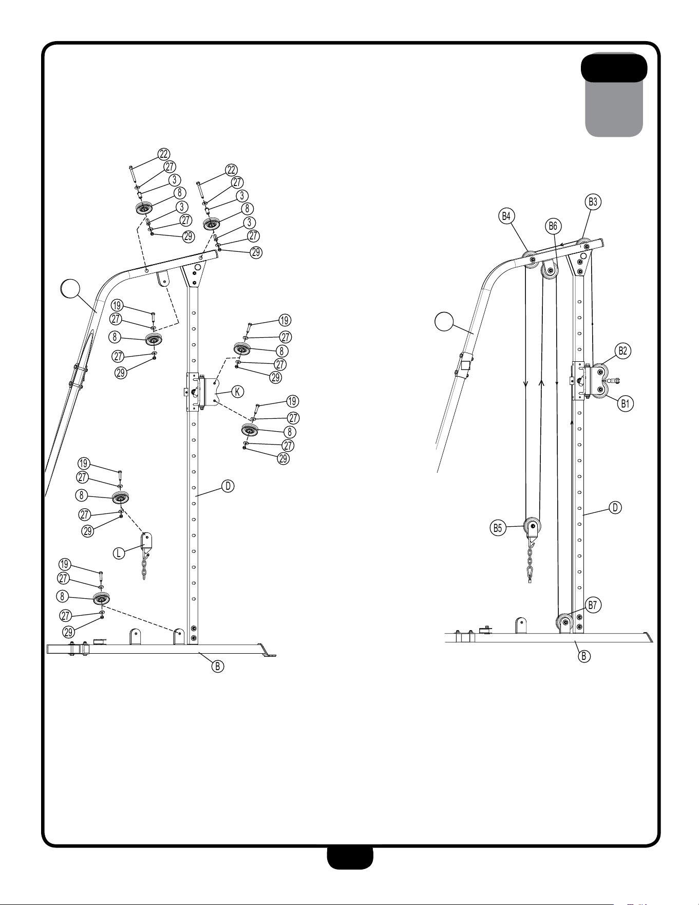
6A. Attach two pulleys to Double Pulley (K) using:
2 - (#19) M10X42mm Hex Head Bolt
4 - (#27) M10 Washer
2 - (#8) 90mm Pulley
2 - (#29) M10 Nylon Lock Nut
6B. Attach a pulley to Pulley Holder (L), the inside holder of Right
Upright (P), and the front holder of Right Lower Beam (B) using:
3 - (#19) M10X42mm Hex Head Bolt
6 - (#27) M10 Washer
3 - (#8) 90mm Pulley
3 - (#29) M10 Nylon Lock Nut
6C. Attach a pulley to the front and rear top openings of Right
Upright (P) using:
2 - (#22) M10X102mm Hex Head Bolt
4 - (#27) M10 Washer
4 - (#3) 25X10.5X32mm Bushing
2 - (#8) 90mm Pulley
2 - (#29) M10 Nylon Lock Nut
6D. Cable Routing: Use a 6740mm Cable (#5). First, route the non-clip
end of the cable over pulley B1 and under then around pulley B2.
Second, route the cable up and over pulley B3 then over and down
pulley B4. Third, route the cable down and around pulley B5 then up
and over pulley B6. Lastly, route the cable down and around pulley
B7 and back up into the cable holder on Handle Assembly (J).
Secure the cable just enough to hold by tightening the socket set
screw (#24) that is pre-installed on Handle Assembly (J).
nOTe:
Finger tighten all hardware first. DO nOT wrench tighten until the
end of step 8, some components may be pre-assembled.
nylon lock nuts will not fully screw onto bolts, must wrench tighten.
sTeP
6
23
B1
B2
B3
B4
B6
B5
B7
F
D
B
D
K
F
L
B
19
27
8
27
29
19
27
8
27
29
19
27
8
27
29
29
27
3
8
3
27
22
29
27
3
8
3
27
22
19
27
8
27
29
19
27
8
27
29
a
E
a
E
a
P
a
P

Be careful to assemble all components
in the sequence they are presented.
sTeP
7
24
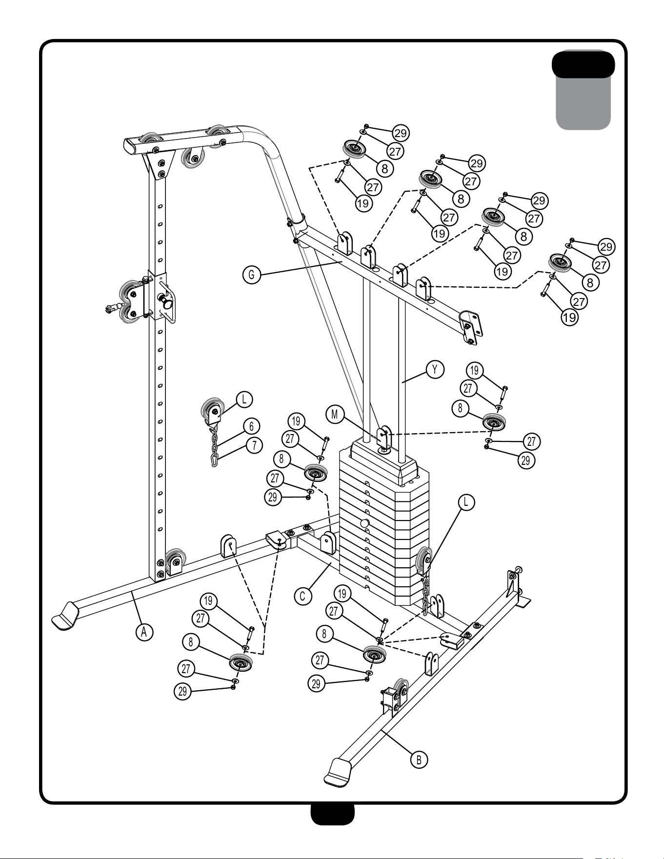
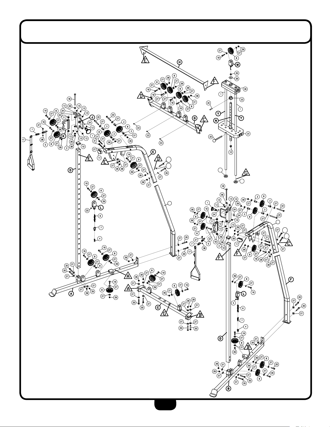
NOTE: This step is to show the placement of the rest of your pulleys
and the hardware you will need to install them. The pulleys in this step
can be attached, however they will have to be removed and put back on
while routing the nal cable which can be found in the next step. To make
things easier for you grab the parts and hardware you will need to
complete this step and place them close to their attachment points.
7A. Attach four pulleys to the four pulley holders located on Support
Beam (G) using:
4 - (#19) M10X42mm Hex Head Bolt
8 - (#27) M10 Washer
4 - (#8) 90mm Pulley
4 - (#29) M10 Nylon Lock Nut
7B. Attach two pulleys to the two pulley holders located on Base
Frame (C), Left Lower Beam (A), and Right Lower Beam (B) using:
6 - (#19) M10X42mm Hex Head Bolt
12 - (#27) M10 Washer
6 - (#8) 90mm Pulley
6 - (#29) M10 Nylon Lock Nut
7C. Attach one pulley to Single Pulley (M) using:
4 - (#19) M10X42mm Hex Head Bolt
8 - (#27) M10 Washer
4 - (#8) 90mm Pulley
4 - (#29) M10 Nylon Lock Nut
7D. Attach one end of a three link chain to snap link and hook the other end of the
chain onto each hook of Pulley Holder (L) and screw an acorn nut onto the end
of each Pulley Holder (L) using:
2 - (#6) Steel Chain
2 - (#7) Snap Link
2 - (#25) M6 Acorn Cap Nut
nOTe:
Finger tighten all hardware first. DO nOT wrench tighten all pulleys
until the end of step 8, some components may be pre-assembled.
nylon lock nuts will not fully screw onto bolts, must wrench tighten.
sTeP
7
25
L
C1
A
C2
C3
4
C4
C5
C6
C7
G
C8
C9
C10
B
C11
L
C
G
B
M
L
6
7
A
C
L
Y
19
27
8
27
29
19
27
8
27
29
19
27
8
27
29
19
27
8
27
29
29
27
8
27
19
29
27
8
27
19
29
27
8
27
19
29
27
8
27
19
Be careful to assemble all components
in the sequence they are presented.
sTeP
8
26
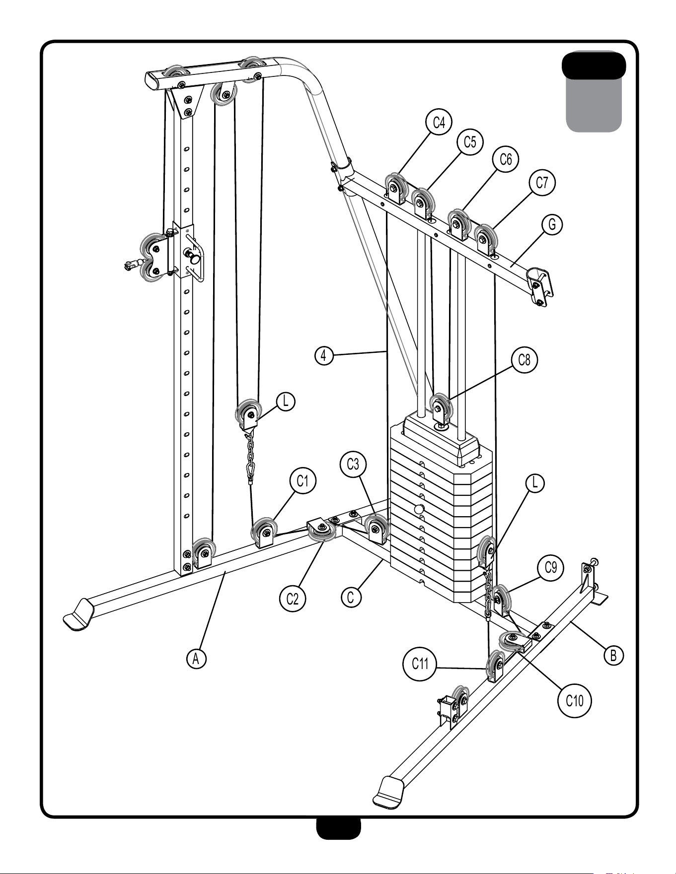
NOTE: Only tighten the pulleys so that they are a little snug, over
tightening them will cause them not to rotate properly.
Cable Routing: Use a 7350mm Cable (#4). First, hook one end of the cable
onto the hook of Pulley Holder (L) that is on the left side above
Lower Left Beam (A). Second, route the cable down, under, and around
pulley C1, then over and around pulley C2, then under pulley C3 and up to
pulley C4. Third, route the cable over pulley C4 and C5 and then down
towards pulley C8. Fouth, route the cable around pulley C8, then back up
and over pulley C6 and C7. Fifth, route the cable down and around pulley
C9, then over and around pulley C10, then under pulley C11 and up to
Pulley Holder (L) that is on the right side. Lastly, hook the other end of the
cable onto the hook of Pulley Holder (L) that is on the right side.
*
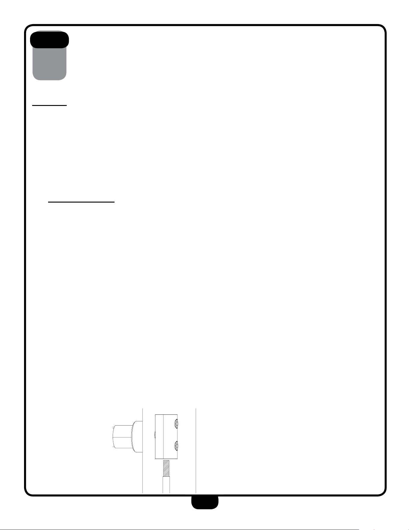
You have completed assembling your BFFT10B machine. The last thing
you’ll need to do is tighten the cables by stripping enough plastic coating
on one side of the cable that is attached to one of the Handle Assemblies
(J). Once their is no slack left, and the coating is stripped off secure the
cable by tightening the socket set screw (#24) that is pre-installed
on Handle Assembly (J) on both the left and right side. See pic. below.
*To see the BFFT10B built live on video go to www.bodysolid.com
nOTe:
Finger tighten all hardware first. wrench tighten all pulleys at the
end of this step, some components may be pre-assembled.
nylon lock nuts will not fully screw onto bolts, must wrench tighten.
strip the plastic coating o the cable
before your tighten it down. be sure to
tighten the allen key screw as much as
possible.
↑
↑
allen key screw
sTeP
8
27
L
C1
A
C2
C3
4
C4
C5
C6
C7
G
C8
C9
C10
B
C11
L
C
G
B
M
L
6
7
A
C
L
Y
19
27
8
27
29
19
27
8
27
29
19
27
8
27
29
19
27
8
27
29
29
27
8
27
19
29
27
8
27
19
29
27
8
27
19
29
27
8
27
19
28
eXPlODeD View DiagRaM
16
16
F
P
41
41
41
41

29
BFFT10B nOTes

1900 S. Des Plaines Ave.
Forest Park, Il 60130
1 (800) 556-3113
Hours: M-F 8:30 - 5:00 CST
c
Copyright 2003. Body-Solid. All rights reserved. Body-Solid reserves the right to change design and specications when we feel it will improve the product.
Body-Solid machines maintain several patented and patent pending features and designs. All rights reserved on all design patents and utility patents.
www.BestFitness.com
BFFT10B
S/N # ������-��-��-����-����
please write your serial number in the boxes below