
&
Assembly Instructions
OWNER’S MANUAL
v. S2FT-112216
S2FT
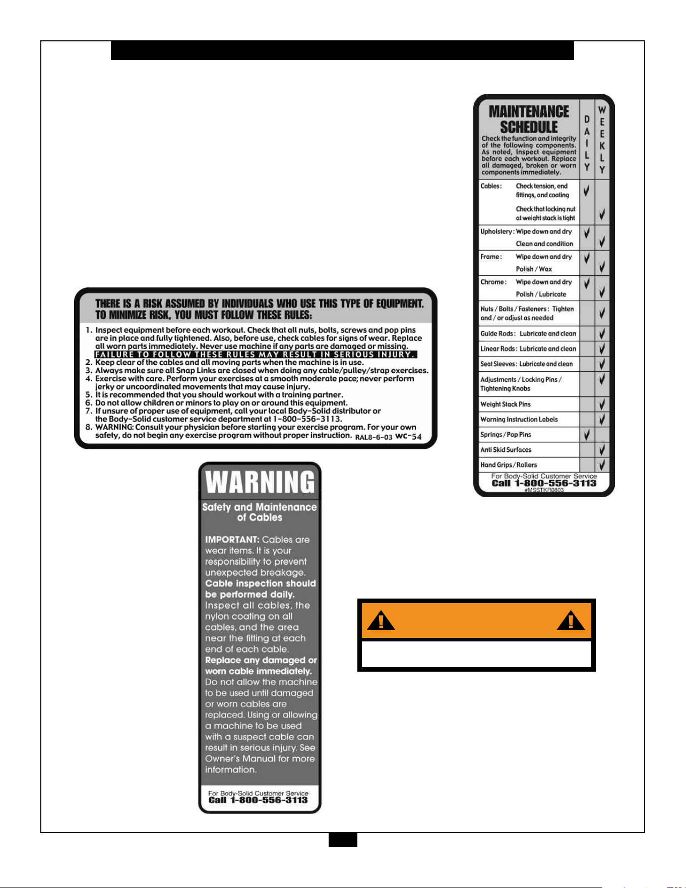
Warning, Safety & Maintenance
2
Be sure that all users carefully read and understand all
warning, safety and maintenance labels on the machine
before each use. Failure to do so may result in death or
serious injury.
It is imperative that you retain this Owner’s Manual and be
sure all warning labels are legible and intact. Replacement
Owner’s Manuals and warning labels are available from your
local Body-Solid dealer.
If you have any questions about the operation, set up or
maintenance of this machine please call our customer service
department at 1 (800) 556-3113.
#DWSM-5
WARNING
Bolt machine to the ground before use

Table of Contents
3
• SAFETY INSTRUCTIONS.............................. PAGE 4
• PREPARATION............................................... PAGE 5
• HARDWARE LIST........................................... PAGE 6
• HARDWARE ILLUSTRATION......................... PAGE 8
• PART / LIST ILLUSTRATION......................... PAGE 13
• ASSEMBLY INSTRUCTIONS........................ PAGE 22
• EXPLODED VIEW......................................... PAGE 36
• CONTACT PAGE........................................... PAGE 38

Important Safety Instructions
4
Beforebeginninganytnessprogram,youshouldobtainacompletephysicalexaminationfromyourphysician.
Il est conseille de subir un examen medical complet avant d’entreprendre tout programme d’exercise.
Si vous avez des etourdissements ou des faiblesses, arretez les exercices immediatement.
Antes de comenzar cualquier programma de ejercicios, deberias tener un examen sico con su doctor.
When using exercise equipment, you
should always take basic precautions,
including the following:
m ReadallinstructionsbeforeusingtheS2FT.
Theseinstructionsarewrittentoensureyoursafety
andtoprotecttheunit.
m Do not remove any safety labels from the
machine.
m Donotallowchildrenonorneartheequipment.
m Usetheequipmentonlyforitsintendedpurpose
asdescribedinthisguide.Donotuseaccessory
attachmentsthatarenotrecommendedbythe
manufacturer.Suchattachmentsmightcause
injuries.
m Wearproperexerciseclothingandshoesforyour
workout,nolooseclothing.
m Keephands,limbs,looseclothing,andlonghairwell
outofthewayofallmovingparts.
m Usecarewhengettingonorofftheunit.
m Donotoverexertyourselforworktoexhaustion.
m Ifyoufeelanypainorabnormalsymptoms,stop
yourworkoutimmediatelyandconsultyour
physician.
m Neveroperateunitwhenithasbeendroppedor
damaged.Returntheequipmenttoaservice
centerforexaminationandrepair.
m Neverdroporinsertobjectsintoanyopeningin
theequipment.
m Alwayschecktheunitanditscablesbeforeeach
use.Makesurethatallfastenersandcablesare
secureandingoodworkingcondition.
m Donotusetheequipmentoutdoorsornearwater.
Personal Safety During Assembly
m Beforebeginningassembly,pleasetakethetime
toreadtheinstructionsthoroughly.
m Readeachstepintheassemblyinstructionsand
followthestepsinsequence.Donotskipahead.
Ifyouskipahead,youmaylearnlaterthatyou
havetodisassemblecomponentsandthatyou
mayhavedamagedtheequipment.
m Assembleandoperatethe
S2FTonasolid,level
surface.Locatetheunitafewfeetfromthewalls
orfurnituretoprovideeasyaccess.
TheS2FT isdesignedforyourenjoyment.Byfollowing
theseprecautionsandusingcommonsense,youwill
havemanysafeandpleasurablehoursof
healthfulexercisewithyourBody-Solid Pro-Club
Functional Trainer.
Afterassembly,youshouldcheckallfunctionsto
ensurecorrectoperation.Ifyouexperienceproblems,
rstrechecktheassemblyinstructionstolocateany
possibleerrorsmadeduringassembly.Ifyouareunable
tocorrecttheproblem,callthedealerfromwhomyou
purchasedthemachineorcall1-800-556-3113forthe
dealernearestyou.
Obtaining Service
PleaseusethisOwner’sManualtomakesurethatall
partshavebeenincludedinyourshipment.When
orderingparts,youmustusethepartnumberand
descriptionfromthisOwner’sManual.Useonly
Body-Solidreplacementpartswhenservicingthis
machine.Failuretodosowillvoidyourwarrantyand
couldresultinpersonalinjury.
Forinformationaboutproductoperationorservice,
checkouttheofcialBody-Solidwebsiteat
www.bodysolid.comorcontactanauthorized
Body-SoliddealeroraBody-Solidfactory-authorized
servicecompanyorcontactBody-Solidcustomer
serviceatoneofthefollowing:
Toll Free: 1-800-556-3113
Phone: 1-708-427-3555
Fax: 1-708-427-3556
Hours: M-F 8:30-5:00 CST
E-Mail: [email protected]
Or write to: Body-Solid, Inc.
Service Department
1900 S. Des Plaines Ave.
Forest Park, IL 60130 USA
Retain this Owner’s Manual for future
reference. If you need to order replacement
parts please be prepared to provide the
following information when contacting us so
that we can assist you better.
1. Model Number
2. Place of Purchase
3. Serial Number (S/N)
4. Part # and Description
Preparation
5
Thankyouforpurchasingthe
S2FT
.ThismachineispartoftheBody-Solidlineofqualitystrengthtraining
machines,whichletsyoutargetspecicmusclegroupstoachievebettermuscletoneandoverallbody
conditioning. To maximize your use of the equipment please study this Owner’sManual thoroughly.
Body-Solidcontinuallyseekswaystoimprovetheperformance,specicationsandproductmanualsinordertoensurethatonly
superiorproductsarereleasedfromourfactories.Pleasetakethetimetocarefullyreadthroughthismanualthoroughly.Instructions
containedinthisdocumentarenotintendedtocoveralldetailsorvariationspossiblewithBody-Solidequipment,ortocoverevery
contingencythatmaybemetinconjunctionwithinstallation,operation,maintenanceortroubleshootingoftheequipment.Even
thoughwehavepreparedthismanualwithextremecare,neitherthepublishernortheauthorcanacceptresponsibilityforanyerrors
in,oromissionfrom,theinformationgiven.Shouldadditionalinformationberequired,orshouldsituationsarisethatarenotcovered
bythismanual,themattershouldbedirectedtoyourlocalBody-Solidrepresentative,ortheServiceDepartmentatBody-SolidInc.
inForestPark,Illinois.
Required Tools
Thebasictoolsthatyoumustobtainbeforeassembling
the
S2FTincludebutarenotlimitedto:
m MetricAllenKeySet
m StandardAllenKeySet
m StandardWrenchSet
m MetricWrenchSet
m AdjustableWrench
m Screwdriver(standardand/orphillips)
Installation Requirements
Followtheseinstallationrequirementswhenassembling
the
S2FT:
Setupthe
S2FTonasolid,atsurface.Asmooth,at
surfaceunderthemachinehelpskeepitlevel.A
levelmachinehasfewermalfunctions.
Provideamplespacearoundthemachine.Open
spacearoundthemachineallowsforeasieraccess.
Insertallboltsinthesamedirection.Foraesthetic
purposes,insertallboltsinthesamedirectionunless
specied(intextorillustrations)todootherwise.
Leaveroomforadjustments.Tightenfastenerssuchas
bolts,nuts,andscrewssotheunitisstable,butleave
roomforadjustments.Donotfullytightenfasteners
untilinstructedintheassemblystepstodoso.
Fill out and mail the warranty card.
Assembly Tips
Readall“Notes”oneachpagebeforebeginningeach
step.
Whileyoumaybeabletoassemblethe
S2FTusingthe
illustrationsonly,importantsafetynotesandothertips
areincludedinthetext.
Somepiecesmayhaveextraholesthatyouwillnotuse.
Useonlythoseholesindicatedintheinstructionsand
illustrations.
NOTE: Withsomanyassembledparts,proper
alignmentandadjustmentiscritical.While
tighteningthenutsandbolts,besuretoleave
roomforadjustments.
NOTE: Thebottlesthataremarked“Poison”isyour
touchuppaint.Keepawayfromchildren.
CAUTION: Obtainassistance!Ifyoufeellikeyoucan’t
assemblethe
S2FTbyyourselfthendo
notattempttodosoasthiscouldresultin
inju
ry.Reviewtheinstallationrequirements
beforeproceedingwiththefollowingsteps.
YourS/N#can
befoundhere
↑

6
S2FT Hardware List
Part# Size Description Quantity
1
2
3
4
5
6
7
8
9
10
11
12
13
14
15
16
M10X105mm
M10X100mm
M10X95mm
M10X90mm
M10X55mm
M10X50mm
M10X30mm
M10X25mm
M8X100mm
M8X25mm
M6X16mm
M8X8mm
3/8”X2.0”
10-32X1/8”
5/16”X1.25”
M5X20mm
HEX HEAD BOLT
HEX HEAD BOLT
HEX HEAD BOLT
HEX HEAD BOLT
HEX HEAD BOLT
HEX HEAD BOLT
BUTTON HEAD CAP SCREW
SOCKET HEAD CAP SCREW
HEX HEAD BOLT
BUTTON HEAD CAP SCREW
PHILLIPS HEAD SCREW
SET SCREW
SOCKET HEAD CAP SCREW
SET SCREW
SHOULDER BOLT
BUTTON HEAD CAP SCREW
20 PCS.
4 PCS.
2 PCS.
4 PCS.
4 PCS.
14 PCS.
4 PCS.
8 PCS.
2 PCS.
8 PCS.
6 PCS.
8 PCS.
2 PCS.
8 PCS.
2 PCS.
2 PCS.

Part# Size Description Quantity
7
S2FT Hardware List
40
41
42
43
44
50
51
52
53
54
55
56
M10
M8
M5
5/16”-18
1/2”
M10
M8
M6
M5
3/8”
M10
M10
NYLON LOCK NUT
NYLON LOCK NUT
NYLON LOCK NUT
NYLON LOCK NUT
FLANGE HEX NUT
FLAT WASHER
FLAT WASHER
FLAT WASHER
FLAT WASHER
LOCK WASHER
LOCK WASHER
LARGE FLAT WASHER
48 PCS.
10 PCS.
4 PCS.
1 PCS.
6 PCS.
96 PCS.
20 PCS.
6 PCS.
2 PCS.
2 PCS.
2 PCS.
8 PCS.
45
8
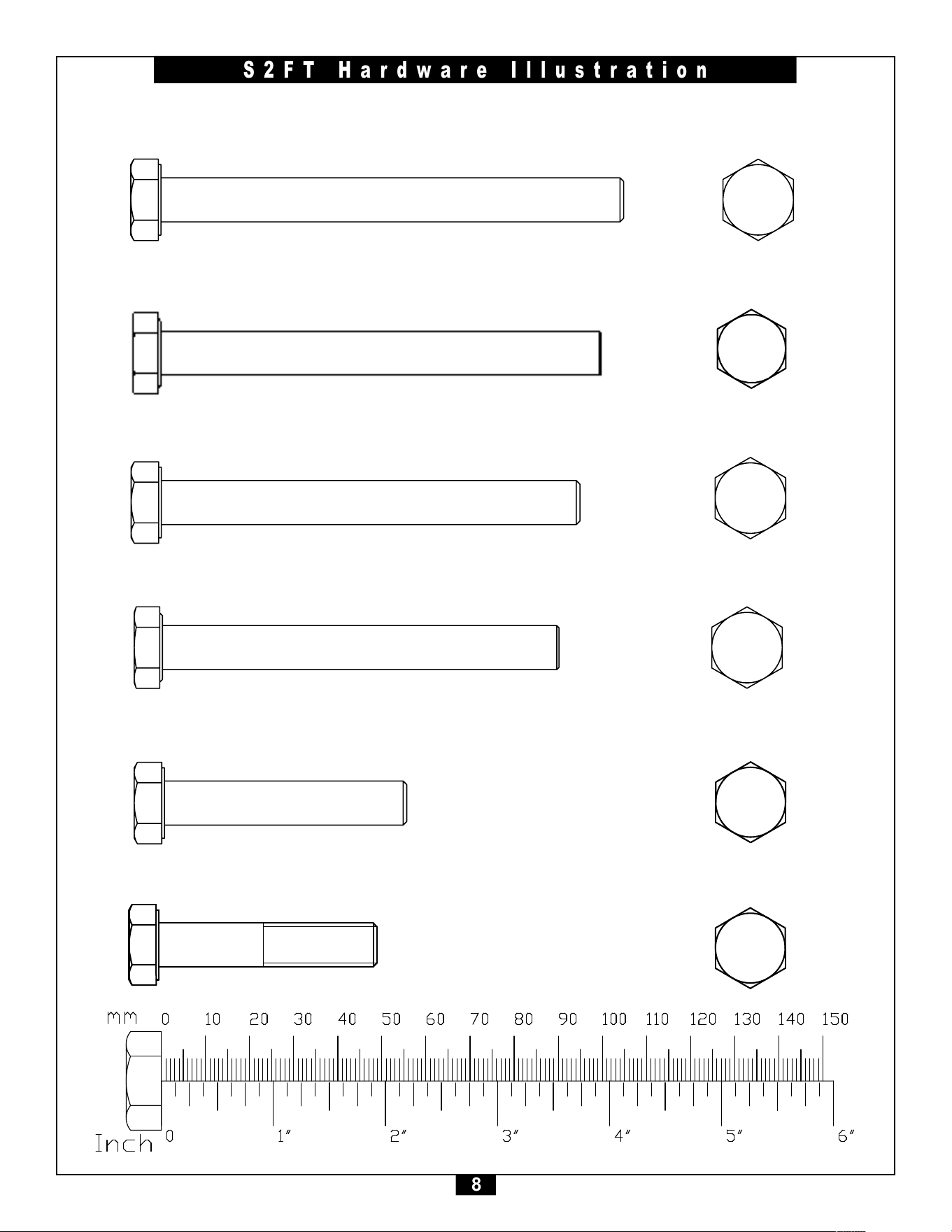
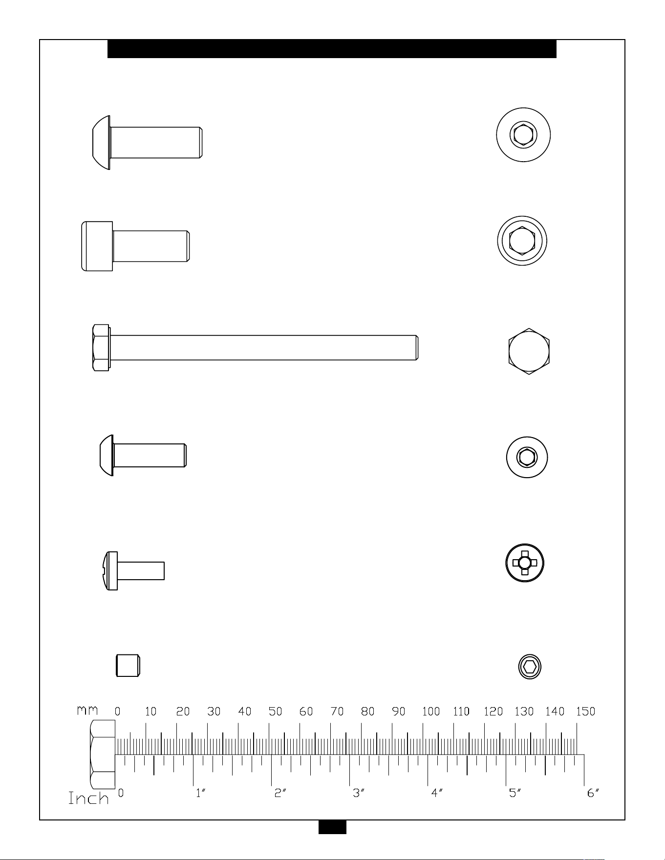
S2FT Hardware Illustration
Part#1 HEX HEAD BOLTM10X105mm QTY.20
Part#2 HEXHEADBOLTM10X100mm QTY.4
Part#3 HEXHEADBOLTM10X95mm QTY.2
Part#4 HEXHEADBOLTM10X90mm QTY.4
Part#5 HEXHEADBOLTM10X55mm QTY.4
Part#6 HEXHEADBOLTM10X50mm QTY.14
Part #1 HEX HEAD BOLT M10X105mm PARTIAL QTY. 4
Part #2 HEX HEAD BOLT M10X35mm PARTIAL QTY. 1
Part #3 HEX HEAD BOLT M10X45mm PARTIAL QTY. 2
Part #4 HEX HEAD BOLT M10X50mm PARTIAL QTY. 8
Part #5 HEX HEAD BOLT M10X65mm PARTIAL QTY. 3
Part #6 HEX HEAD BOLT M10X75mm PARTIAL QTY. 5
Part #7 HEX HEAD BOLT M10X80mm PARTIAL QTY. 2
45
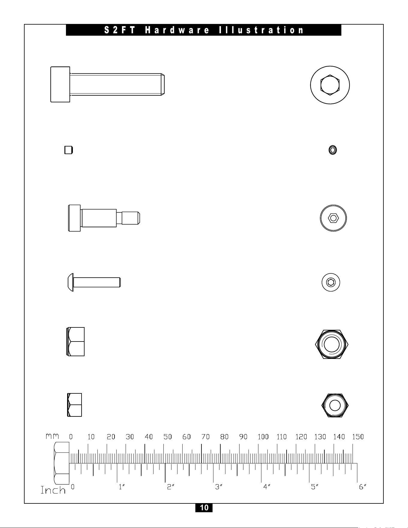
9
S2FT Hardware Illustration
Part#7 BUTTON HEAD CAP SCREWM10X30mm QTY.7
Part#8 SOCKET HEAD CAP SCREW M10X25mm QTY.8
Part#9 HEXHEADBOLTM8X100mm QTY.2
Part#10 BUTTONHEADCAPSCREWM8X25mm QTY.8
Part#11 PHILLIPSHEADSCREWM6X16mm QTY.6
Part#12 SETSCREWM8X8mm QTY.4
45
10
S2FT Hardware Illustration
Part#13 SOCKET HEAD CAP SCREW3/8”X2.0” QTY.1
Part#14 SETSCREW10-32X1/8” QTY.8
Part#15 SHOULDERBOLT5/16”X1.25” QTY.1
Part#40 NYLON LOCK NUT M10 QTY.48
Part#41 NYLON LOCK NUT M8 QTY.10
Part#16 BUTTONHEADCAPSCREWM5X20mm QTY.2
45
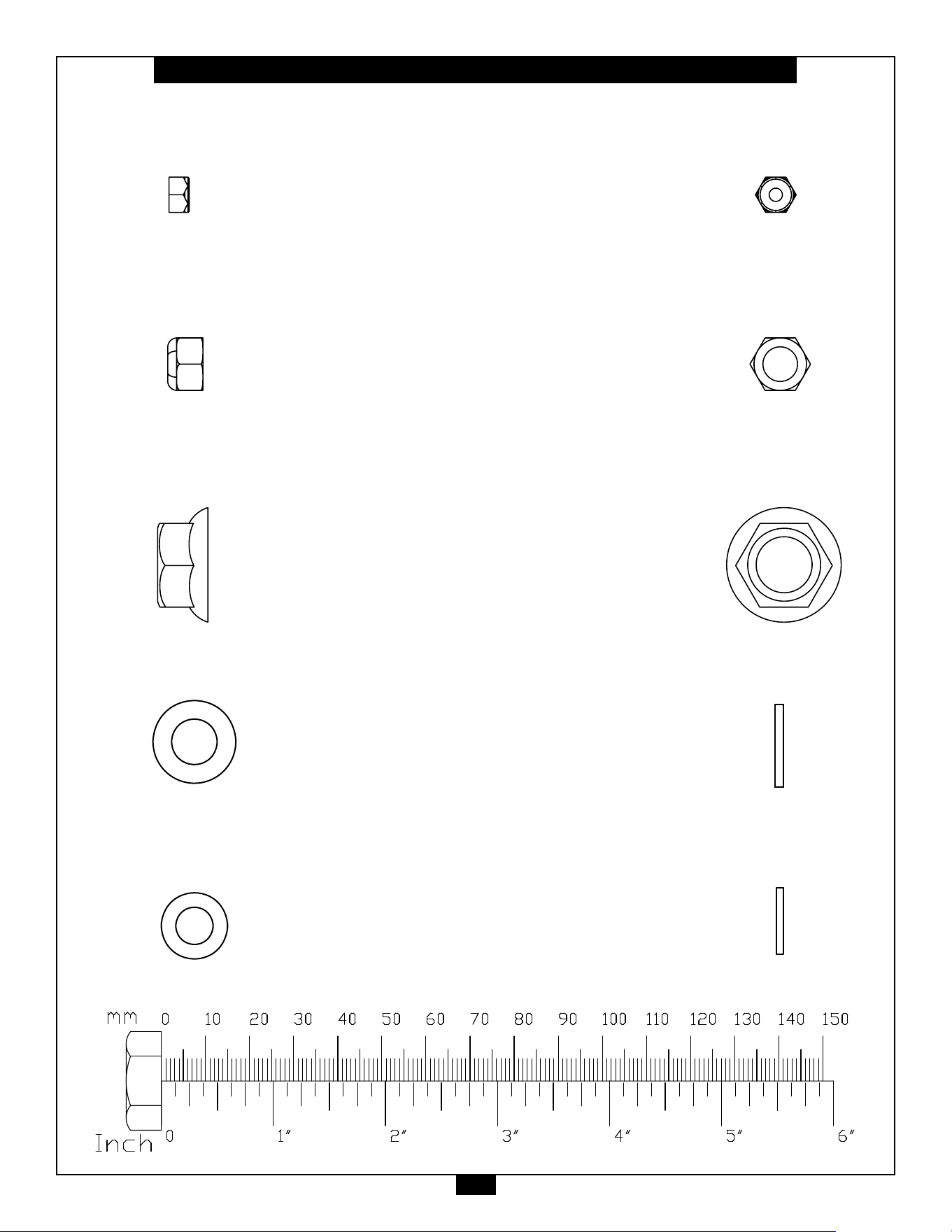
11
S2FT Hardware Illustration
Part#42 NYLON LOCK NUTM5 QTY.4
Part#43 NYLONLOCKNUT5/16” QTY.1
Part#44 FLANGENUT1/2” QTY.6
Part#50 FLAT WASHER M10 QTY.96
Part#51 FLAT WASHER M8 QTY.20
ijij
ijij
ijij
ijij
ij
ijij
ijij
ijij
ijij
ij
ijij
ijij
ijij
ijij
ij
ijij
ijij
ijij
ijij
ij
45
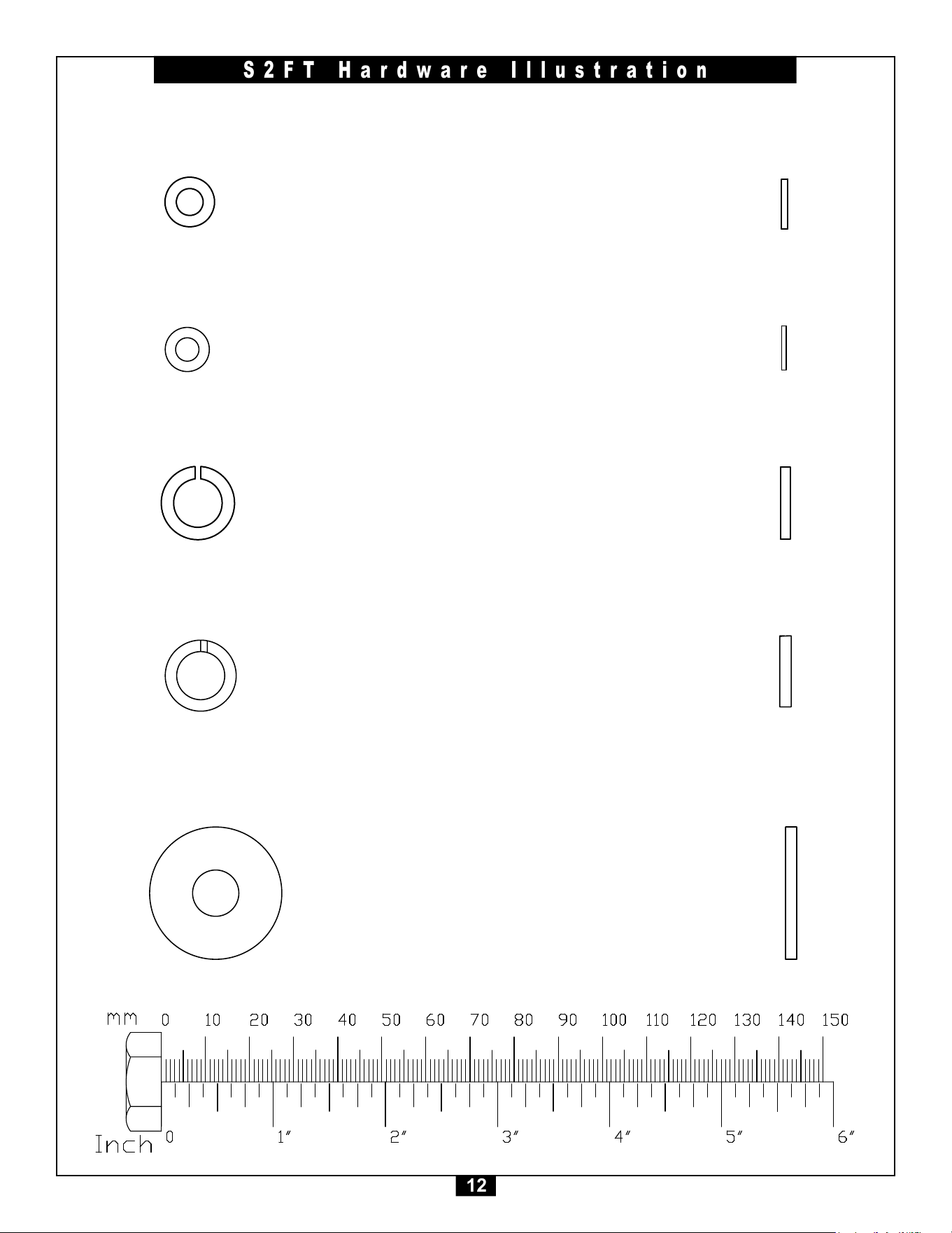
12
S2FT Hardware Illustration
Part#52 FLATWASHERM6 QTY.6
Part#53 FLATWASHERM5 QTY.2
Part#54 LOCKWASHER3/8” QTY.2
ijij
ijij
ijij
ijij
ij
ijij
ijij
ijij
ijij
ij
ijij
ijij
ijij
ijij
ij
ijij
ijij
ijij
ijij
ij
Part#55 LOCK WASHER M10 QTY.2
Part#56 LARGE FLAT WASHER M10 QTY.8
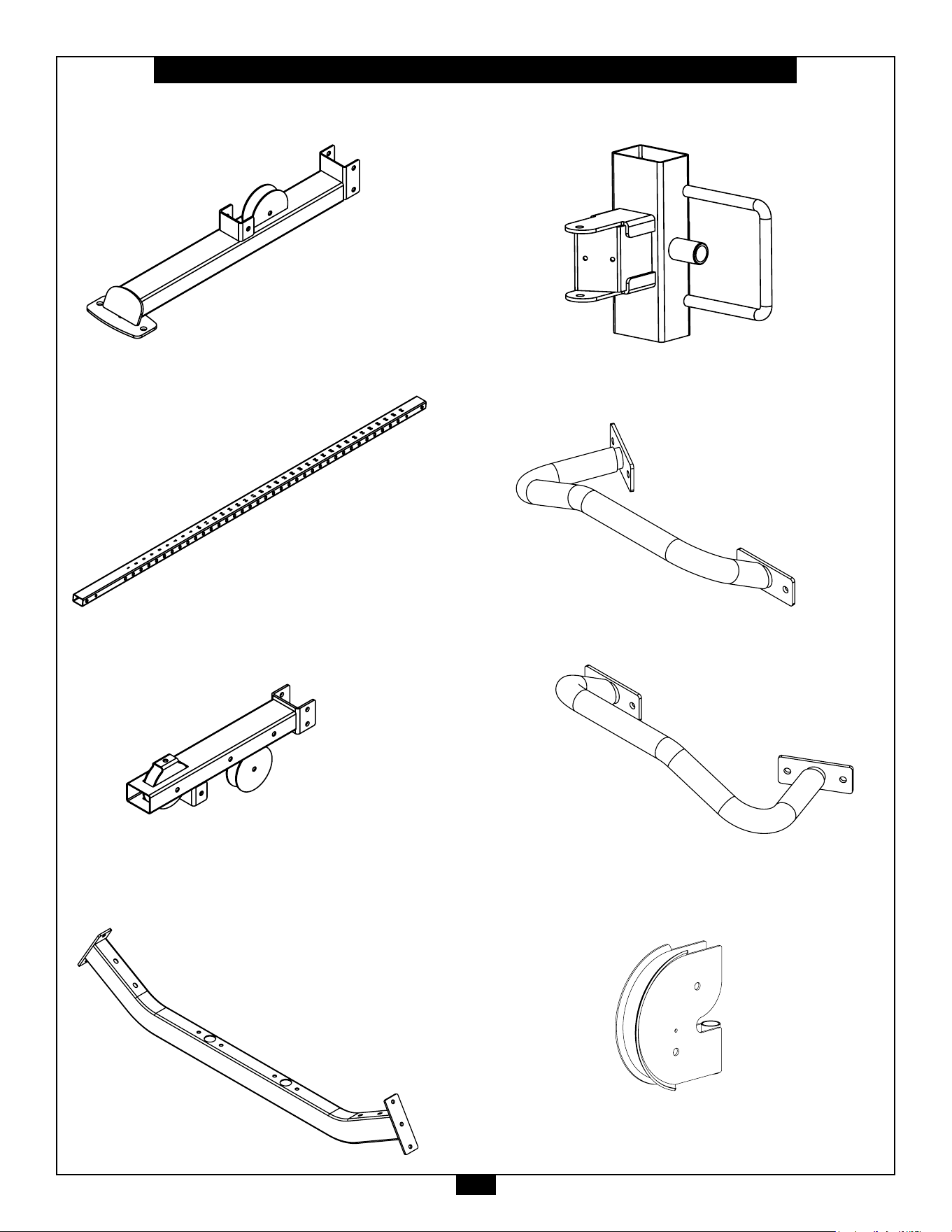
13
S2FT Parts List/Illustration
PART A - BASE FRAME, 2PCS.
PART B - RIGHT GUIDE POST, 1PC.
PART C - TOP SIDE FRAME, 2PCS.
PART D - CENTER TOP FRAME, 1PC.
PART E - RIGHT SWIVEL ADJUSTER, 1PC.
PART F - RIGHT CHIN UP HANDLE, 1PC.
PART G - LEFT CHIN UP HANDLE, 1PCS.
PART H - PULLEY HOLDER, 2PCS.
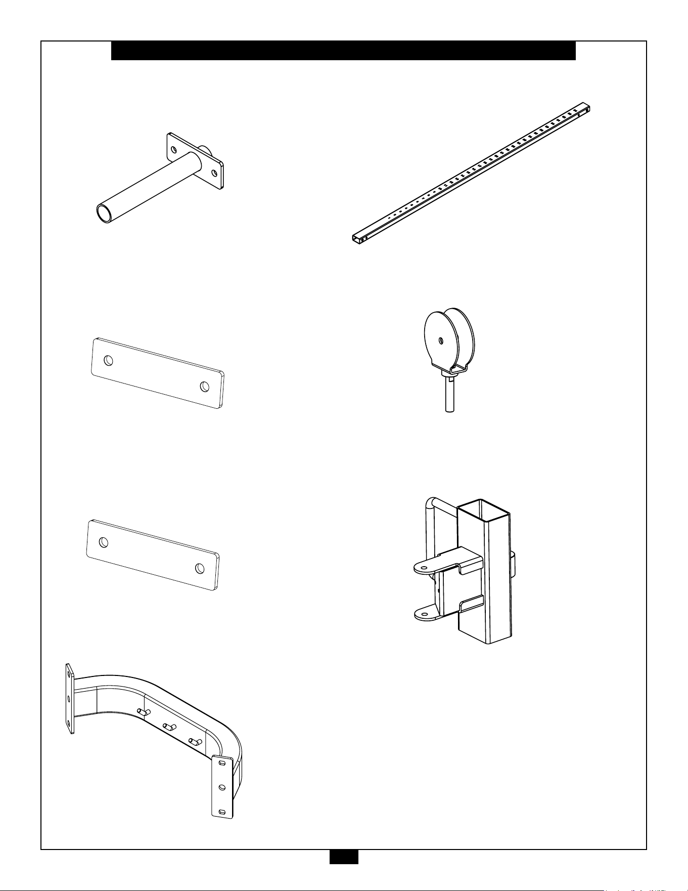
14
S2FT Parts List/Illustration
PART J - PULL UP HANDLE, 2PCS.
PART K - STEEL PLATE, 2PCS.
120mm x 50mm x 5mm
PART L - STEEL PLATE 2PCS.
170mm x 50mm x 5mm
PART M - CENTER FRAME, 2PCS.
PART N - LEFT GUIDE POST , 1PC.
PART P - SWIVEL PULLEY BRACKET, 2PCS.
PART Q - LEFT SWIVEL ADJUSTER, 1PC.
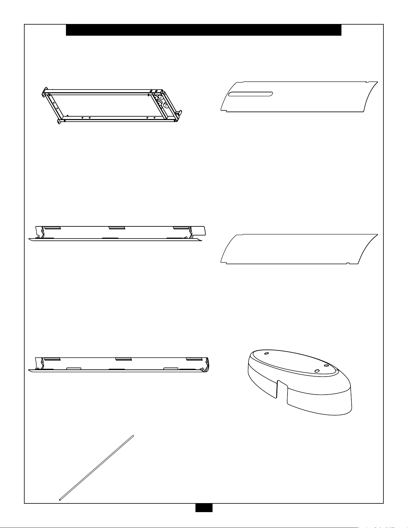
15
S2FT Parts List/Illustration
PART WA - WEIGHT STACK FRAME, 2PCS.
PART WD - CHROME GUIDE ROD, 4PCS.
PART WB - SHORT SIDE SHROUD, 2PCS.
PART WC - LONG SIDE SHROUD, 2PCS.
PART WE - RIGHT FRONT SHROUD, 1PC.
PART WF - RIGHT REAR SHROUD, 1PCS.
PART WG - TOP SHROUD, 2PCS.
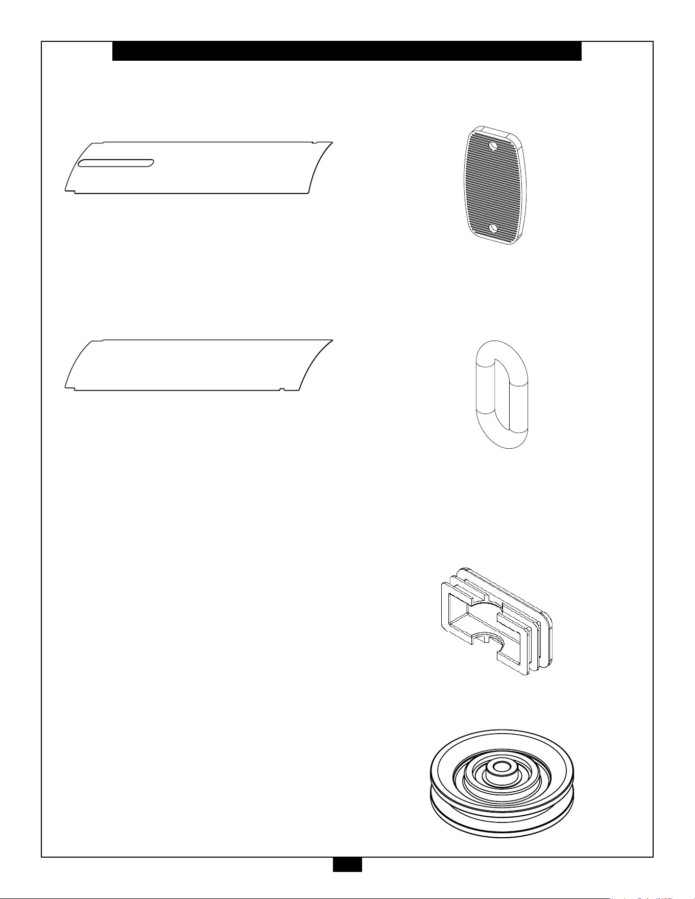
16
S2FT Parts List/Illustration
PART WH - LEFT FRONT SHROUD, 1PC.
PART WJ - LEFT REAR SHROUD, 1PCS.
PART #60 - FOOT PAD, 8PCS.
PART #61 - CHAIN LINK, 2PCS.
PART #62 - PLASTIC END CAP, 2PCS.
75x50mm
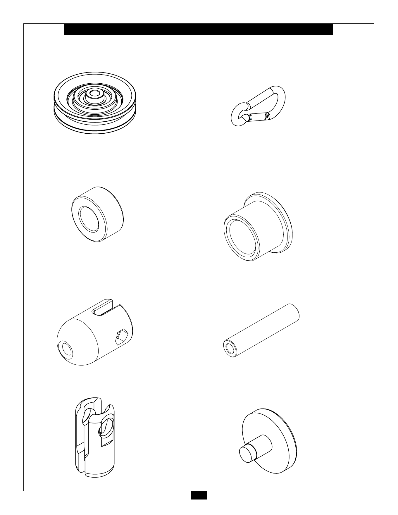
PART #63 - LARGE PULLEY, 6PCS.
17
S2FT Parts List/Illustration
PART #64 - SMALL PULLEY, 14PCS.
PART #65 - RUBBER SLEEVE, 8PCS.
PART #66 - CABLE BUMPBER, 2PCS.
PART #67 - CABLE CONNECTOR, 2PCS.
PART #68 - SNAP LINK, 2PCS.
PART #69 - BUSHING, 4PCS.
ø28xø22x18mm
PART #70 - STEEL TUBE, 2PCS.
ø16xø8.5x75mm
PART #71 - PLASTIC STOPPER, 4PCS.
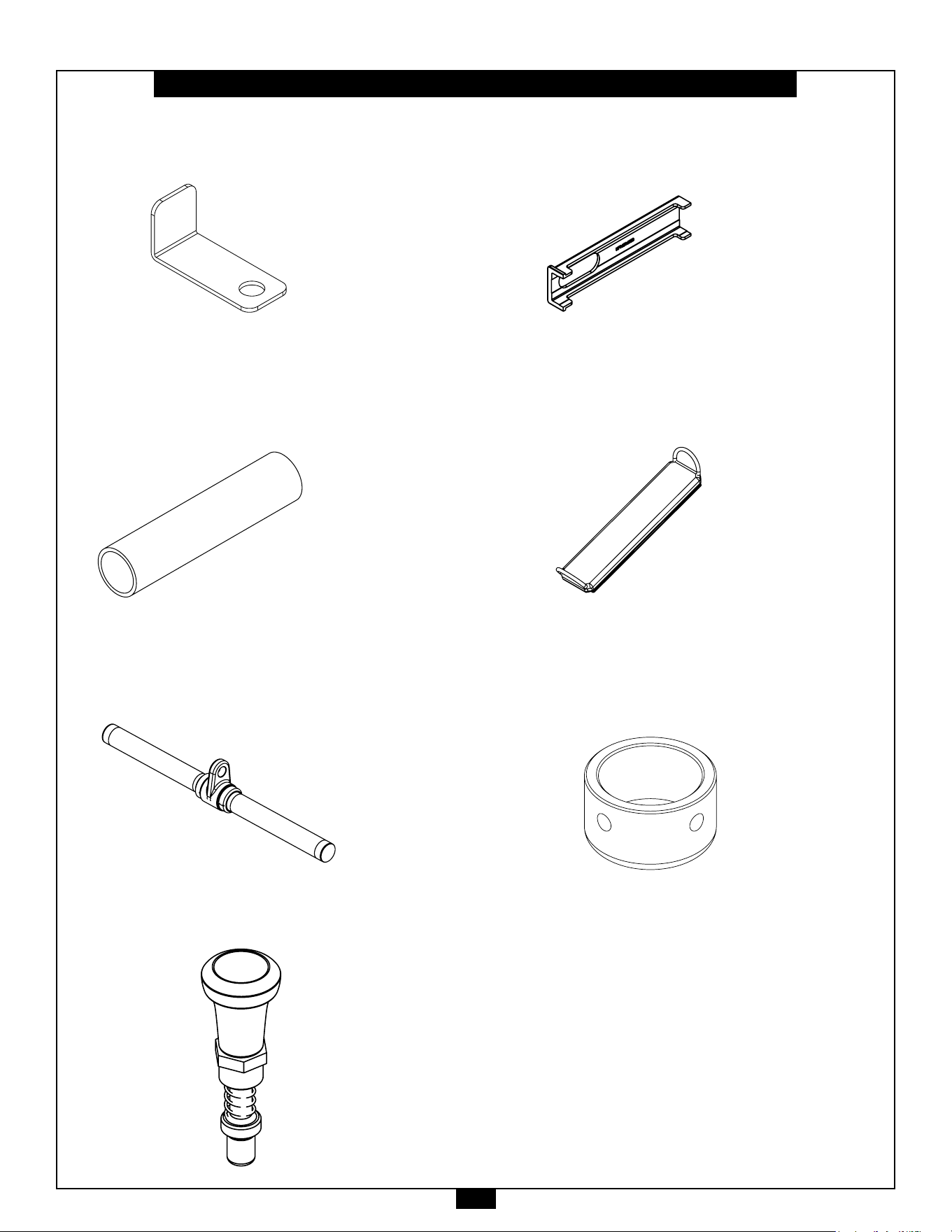
PART #72 - STEEL BRACKET, 4PCS.
PART #73 - HANDLE GRIP, 1PC.
PART #74 - LOW ROW BAR, 1PC.
PART #75 - POP PIN, 2PCS.
PART #76 - PLASTIC BUSHING, 4PCS.
PART #77 - ANKLE CUFF, 1PCS.
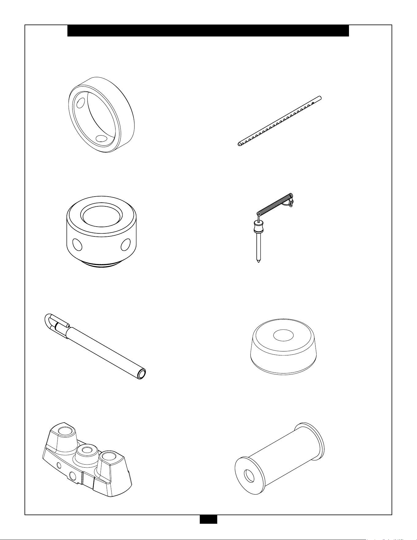
PART #79 - HANDLE END CAP, 2PCS.
ø39.5xø32.5x19mm
19
S2FT Parts List/Illustration
PART #80 - HANDLE END RING, 2PCS.
ø39.5xø32.5x9.5mm
PART #81 - SHAFT COLLAR, 4PCS.
PART #82 - SHORT BAR, 1PC.
PART #83 - TOP PLATE, 2PCS.
PART #84 - SELECTOR ROD, 2PCS.
PART #85 - SELECTOR PIN, 2PCS.
PART #86 - RUBBER DONUT, 4PCS.
PART #87 - WEIGHT RISER, 4PCS.
20
S2FT Parts List/Illustration
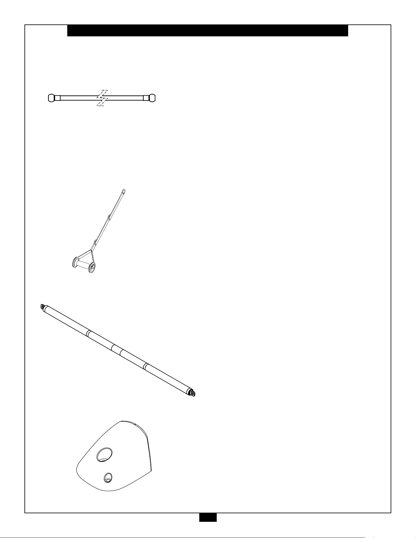
PART #88 - CABLE, 2PCS.
PART #89 - STRAP HANDLE, 2PCS.
PART #90 - LONG BAR, 1PC
PART #91 - ROCK CLIMBING GRIP, 2PCS.
3$5738//(<63&6
3$57&$%/(3&6
3$57&$33&6
3$57+$1'/((1'&$33&6
3$57+$1'/(5,1*3&6
6$&3DUWV/LVW,OOXVWUDWLRQ
PP
3$57%86+,1*3&6
45
21
Notes
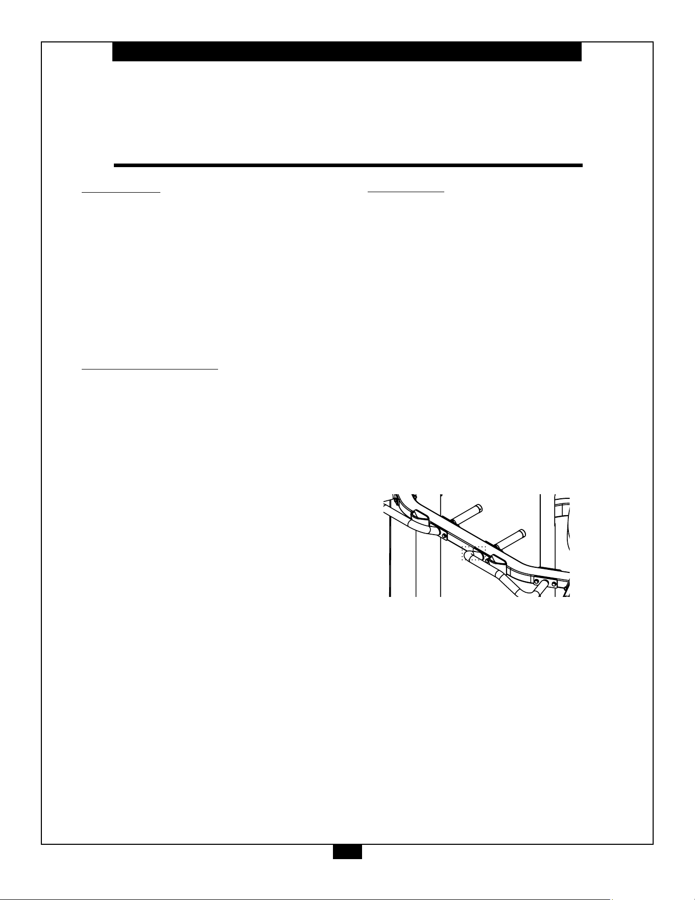
PCL Badge Location

22
STEP
1
Be careful to assemble all components
in the sequence they are presented.
NOTE:
Finger tighten all hardware in this step. DO NOT wrench tighten unless instructed.
Some components may be pre-assembled. Nylon lock nuts will not fully screw onto
bolts, they must be wrench tighten to fully go on.
1A. AttachtwoLongMetalShrouds(WC) totwoWeightStackFrames(WA)
using:
4 - (#10) M8X25mm Button Head Cap Screw
8 - (#51) M8 Flat Washer
4 - (#41) M8 Nylon Lock Nut
1. AttachtwoCenterFrames(M)toWeightStackFrames(WA)using:
8 - (#8) M10X25mm Socket Head Cap Screw
8 - (#56) M10 Large Flat Washer
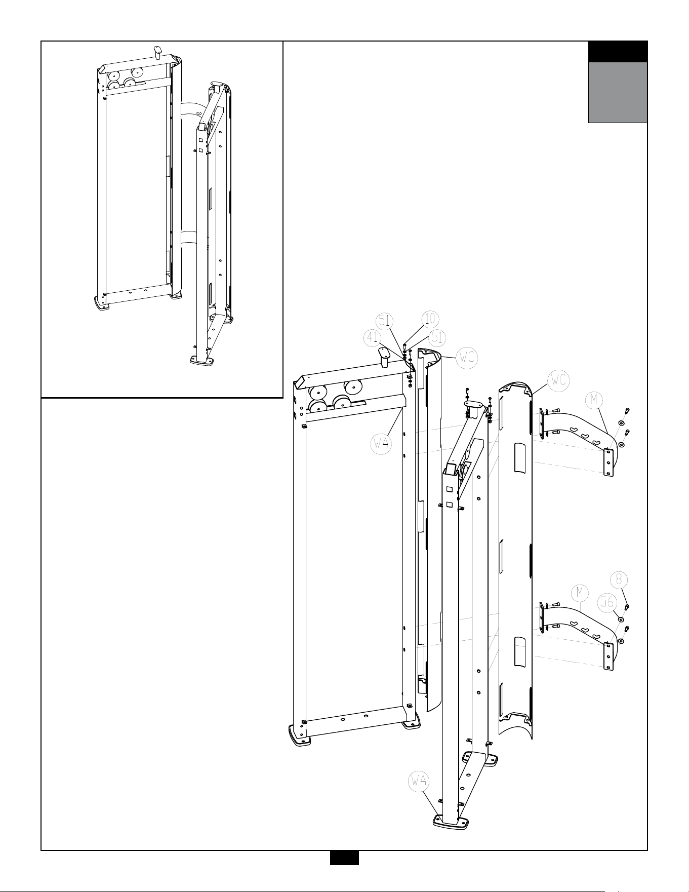
STEP
1
AboveshowsStep1assembledandcompleted.
23

24
STEP
2
Be careful to assemble all components
in the sequence they are presented.
NOTE:
Finger tighten all hardware in this step. DO NOT wrench tighten unless instructed.
Some components may be pre-assembled. Nylon lock nuts will not fully screw onto
bolts, they must be wrench tighten to fully go on.
2A. AttachtwoBaseFrames(A) toWeightStackFrames(WA)using:
4 - (#1) M10X105mm Hex Head Bolt
8 - (#50) M10 Flat Washer
4 - (#40) M10 Nylon Lock Nut
2B. AttachtwoTopSideFrames(C)toWeightStackFrames(WA)using:
4 - (#1) M10X105mm Hex Head Bolt
8 - (#50) M10 Flat Washer
4 - (#40) M10 Nylon Lock Nut
2C. AttachRightGuidePost(B)toRightSideofBaseFrame&TopSide
Frame(A & C)using:
2 - (#4) M10X90mm Hex Head Bolt
4 - (#50) M10 Flat Washer
2 - (#40) M10 Nylon Lock Nut
2D. AttachLeftGuidePost(N)toLeftSideofBaseFrame&TopSide
Frame(A & C)using:
2 - (#4) M10X90mm Hex Head Bolt
4 - (#50) M10 Flat Washer
2 - (#40) M10 Nylon Lock Nut
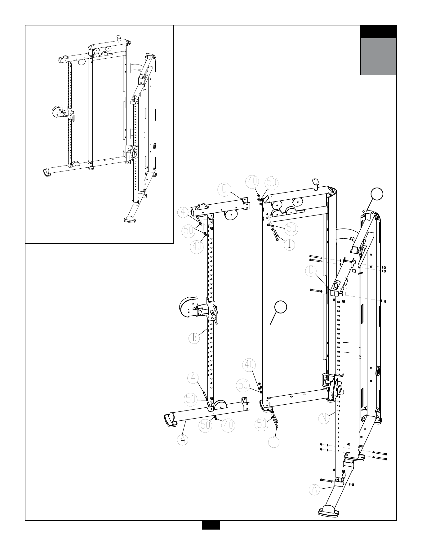
STEP
2
AboveshowsStep2assembledandcompleted.
25
WA
WA

26
STEP
3
Be careful to assemble all components
in the sequence they are presented.
NOTE:
Finger tighten all hardware in this step. DO NOT wrench tighten unless instructed.
Some components may be pre-assembled. Nylon lock nuts will not fully screw onto
bolts, they must be wrench tighten to fully go on.
3A. InstallChromeGuideRods(WD)intotheholesintheWeightStackFrames(WA).
3B. InstallWeightRisers(#87) & RubberDonuts(#67)andslidetothebottom
oftheGuideRods
Important Notes:
1. Install the rod ends with side holes into the bottom section of the Weight
Stack Frame.
2. If 20pcs of weight plates are to be installed, do not install Weight Risers (87)
3C. TiltGuideRods(WD) awayfromtheWeightStackFrame(WA) andinstall15pcs
ofweightplates.Becarefultoholdguiderodssteadilywheninstalling
weightplates.
3D. InstallTopPlate&SelectorRodAssembly(#83)ontotheGuideRods(WD) .
3E. InstallWeightStackPin(#85)usingthekeyringendthroughtheSwivelPully
Bracket(P).
3F. InstallTwo1/2”FlangeHexNut(#44) &SwivelPulleyBracket(P)ontothe
TopPlate(#83) .
3G. InstallShaftCollars(#81)ontotheGuideRods(WD)
3H. SlideShaftCollars(#81)upwardsotheylocktheguiderodsintopositionby
tighteningthefourM8x8mmSetScrews(#12).
3J. RepeattheSameSteps(3Ato3H)ontheothersideofthemachine.
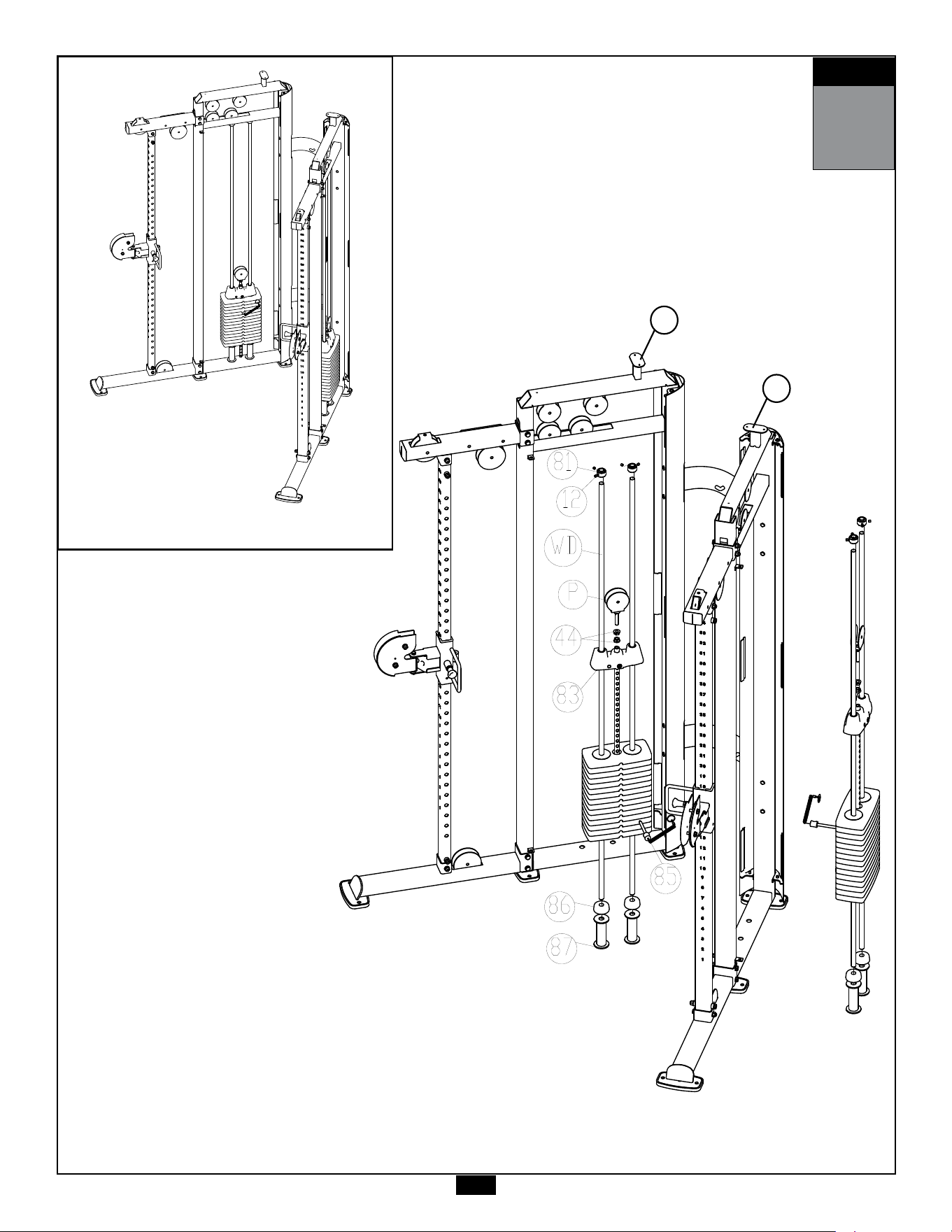
27
STEP
3
AboveshowsStep3assembledandcompleted.
WA
WA

28
STEP
4
Be careful to assemble all components
in the sequence they are presented.
NOTE:
Wrench tighten ALL hardware at the end of Step 4A. Some components may be
pre-assembled. Nylon lock nuts will not fully screw onto bolts, they must be wrench
tighten to fully go on.
4A. AttachCenterTopFrame(D) toTopSideFrames(C)using:
4 - (#1) M10X105mm Hex Head Bolt
8 - (#50) M10 Flat Washer
4 - (#40) M10 Nylon Lock Nut
2 - (L) Steel Plate
4B. AttachRightChinUpHandle(F)&PullUpHandle(J)toCenter
TopFrame(D)using:
4 - (#1) M10X105mm Hex Head Bolt
8 - (#50) M10 Flat Washer
4 - (#40) M10 Nylon Lock Nut
1 - (K) Steel Plate
4C. AttachLeftChinUpHandle(G) &PullUpHandle(J)toCenter
TopFrame(D)using:
4 - (#1) M10X105mm Hex Head Bolt
8 - (#50) M10 Flat Washer
4 - (#40) M10 Nylon Lock Nut
1 - (K) Steel Plate
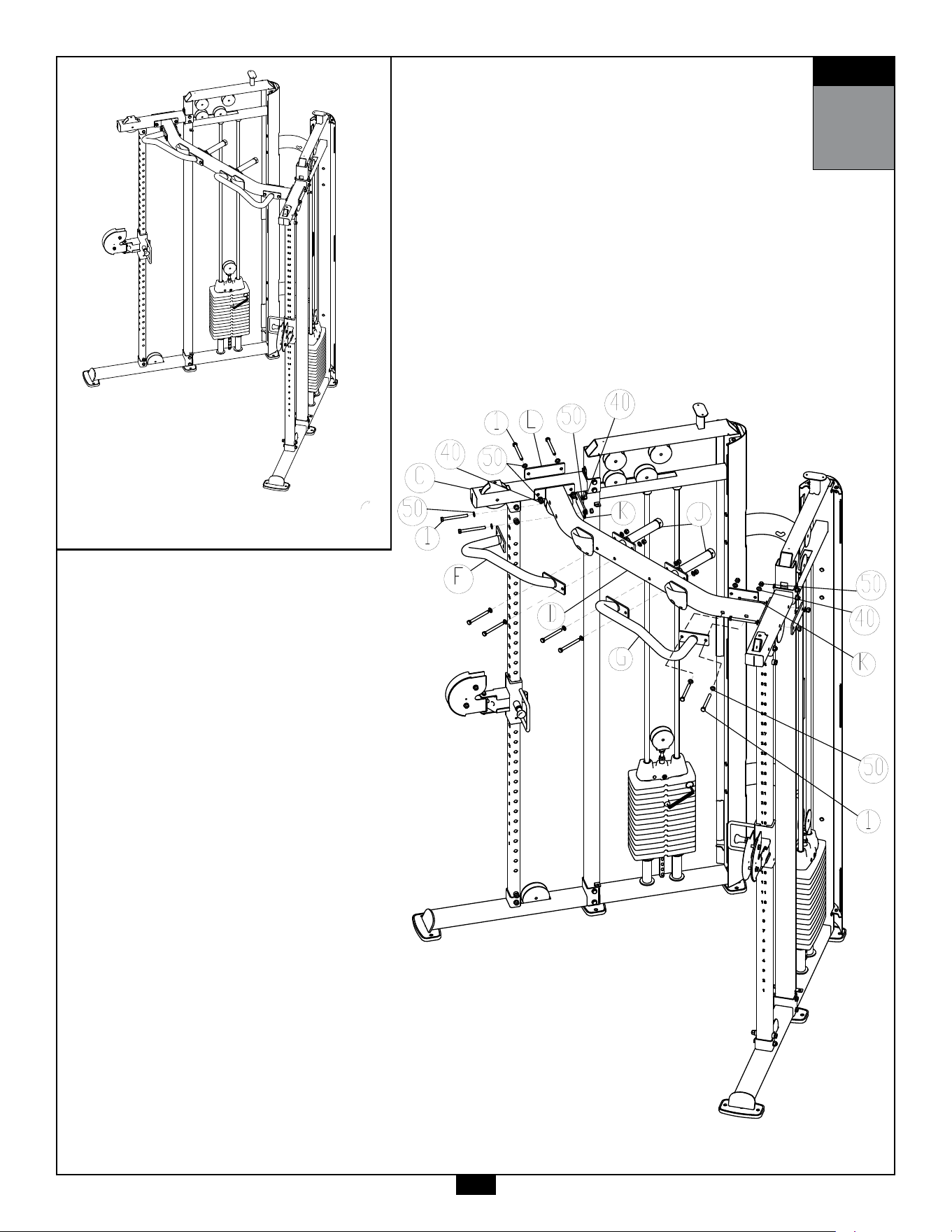
STEP
4
AboveshowsStep4assembledandcompleted.
29

30
STEP
5
Be careful to assemble all components
in the sequence they are presented.
NOTE:
Wrench tighten ALL hardware at the end of Each Step. Some components may be
pre-assembled. Nylon lock nuts will not fully screw onto bolts, they must be wrench
tighten to fully go on.
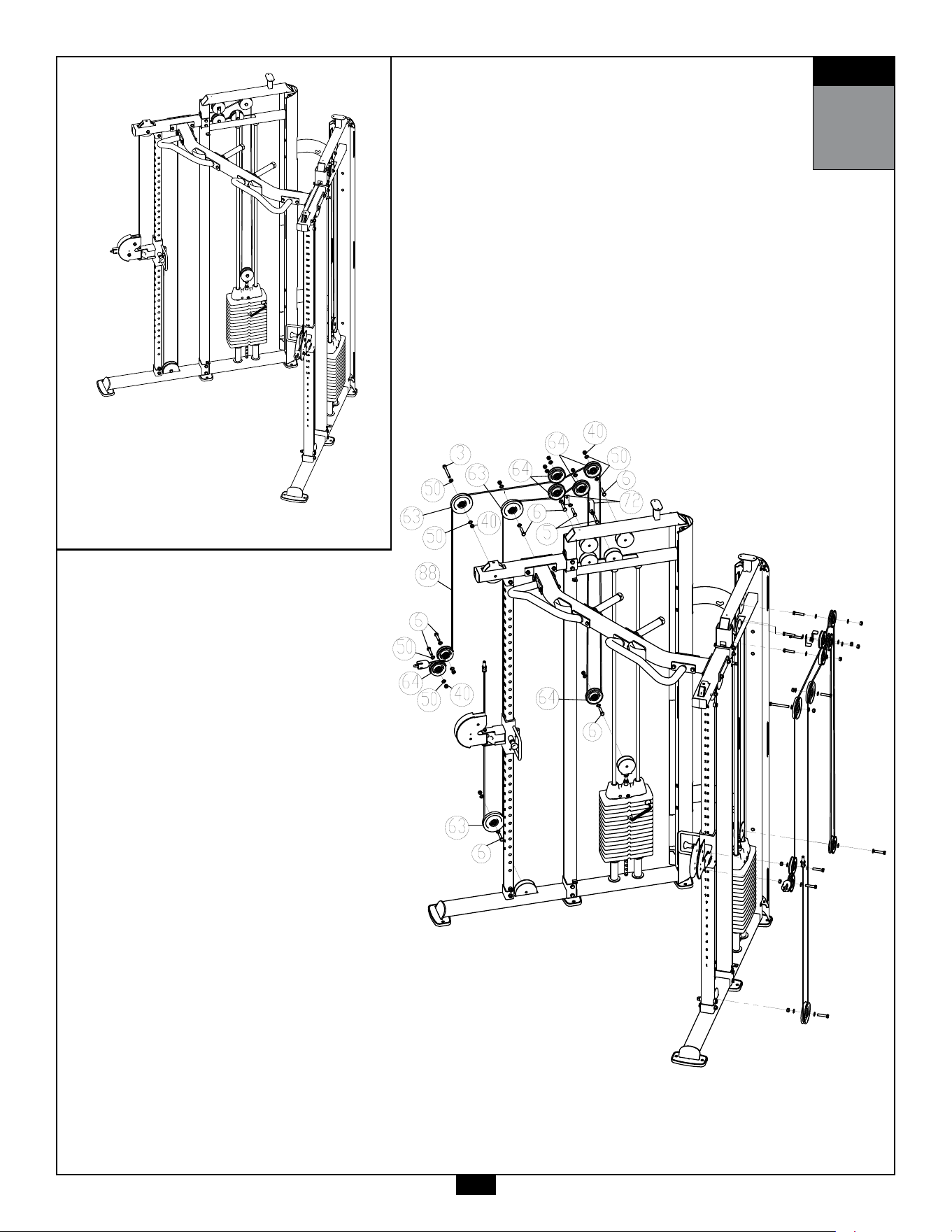
5A. InstallCable(#88)whileinstallingthreeLargePulleys(#63)and
SevenSmallPulleys(#64) ontheRightSideoftheMachineasshown
inStep5Drawingusing:
1 - (#3) M10X95mm Hex Head Bolt
2 - (#5) M10X55mm Hex Head Bolt
7 - (#6) M10X50mm Hex Head Bolt
20 - (#50) M10 Flat Washer
10 - (#40) M10 Nylon Lock Nut
2 - (#72) Steel Bracket
5B. RepeatthepreviousStep(5A)ontheothersideofthemachine.
31
STEP
5
AboveshowsStep5assembledandcompleted.

32
STEP
6
Be careful to assemble all components
in the sequence they are presented.
NOTE:
Wrench tighten ALL hardware at the end of Each Step. Some components may be
pre-assembled. Nylon lock nuts will not fully screw onto bolts, they must be wrench
tighten to fully go on.
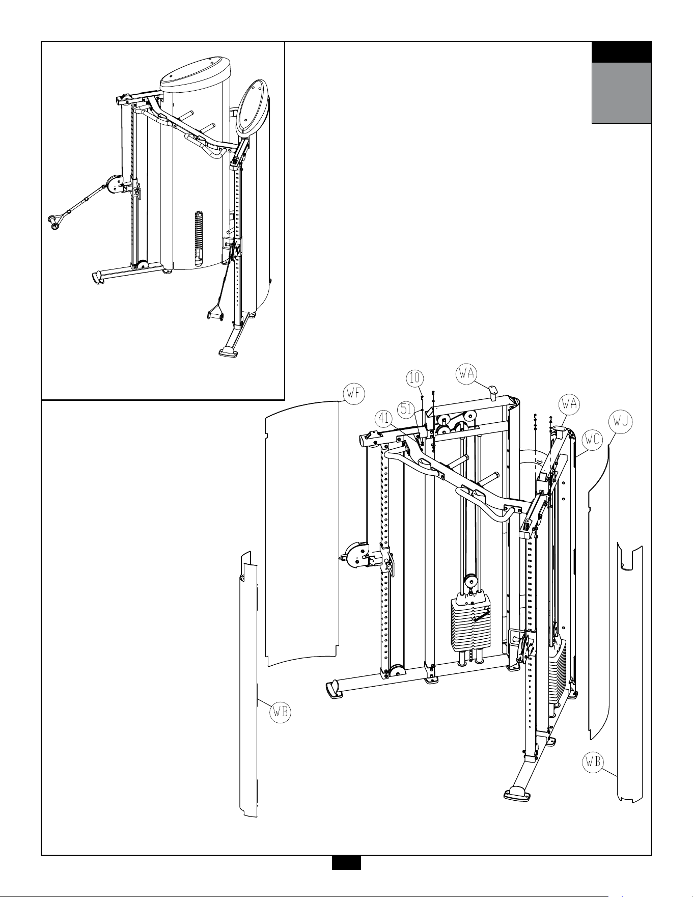
6A. AttachtwoShortMetalShrouds(WB)toWeightStackFrames(WA)
using:
4 - (#10) M8X25mm Button Head Cap Screw
8 - (#51) M8 Flat Washer
4 - (#41) M8 Nylon Lock Nut
6B. BendtheRightRearShroud(WF)andinsertittotheside
slotsoftheMetalShrouds(WB & WC).
6C. BendtheLeftRearShroud(WJ)andinsertittotheside
slotsoftheMetalShrouds(WB & WC).
33
STEP
6
AboveshowsStep6assembledandcompleted.

34
STEP
7
Be careful to assemble all components
in the sequence they are presented.
NOTE:
Wrench tighten ALL hardware at the end of Each Step. Some components may be
pre-assembled. Nylon lock nuts will not fully screw onto bolts, they must be wrench
tighten to fully go on.
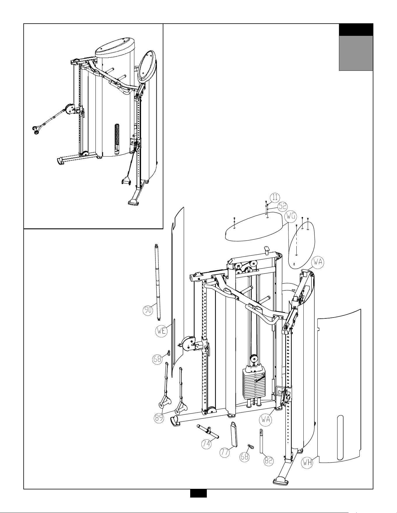
7A. BendtheRightFrontShroud(WE)andinsertittotheside
slotsoftheMetalShrouds(WB & WC).
7B. BendtheLeftRearShroud(WH)andinsertittotheside
slotsoftheMetalShrouds(WB & WC).
7C. AttachTwoTopShrouds(WG)toWeightStackFrames(WA)using:
6 - (#11) M6X16mm Phillips Head Screw
6 - (#52) M6 Flat Washer
35
STEP
7
AboveshowsStep7assembledandcompleted.
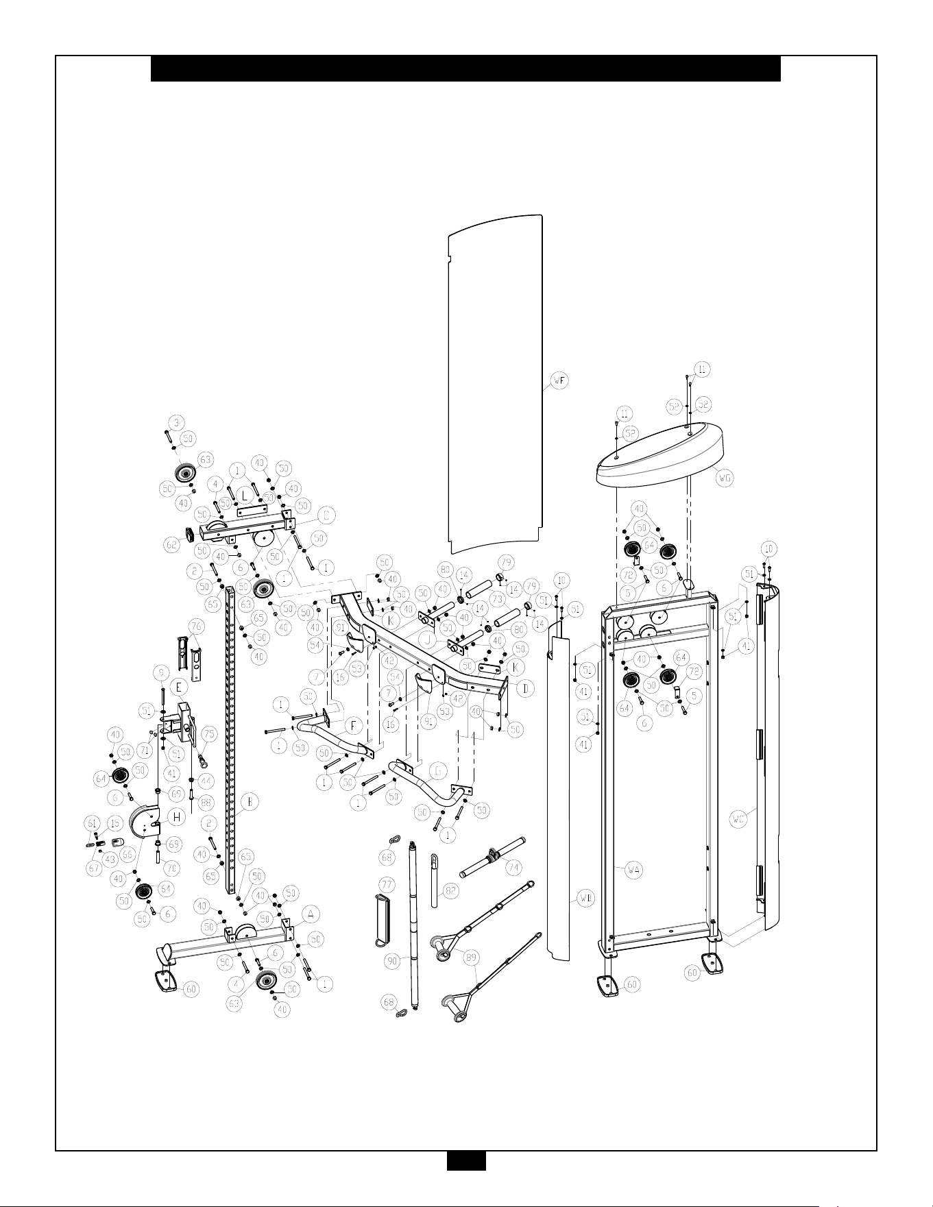
36
S2FT Exploded View
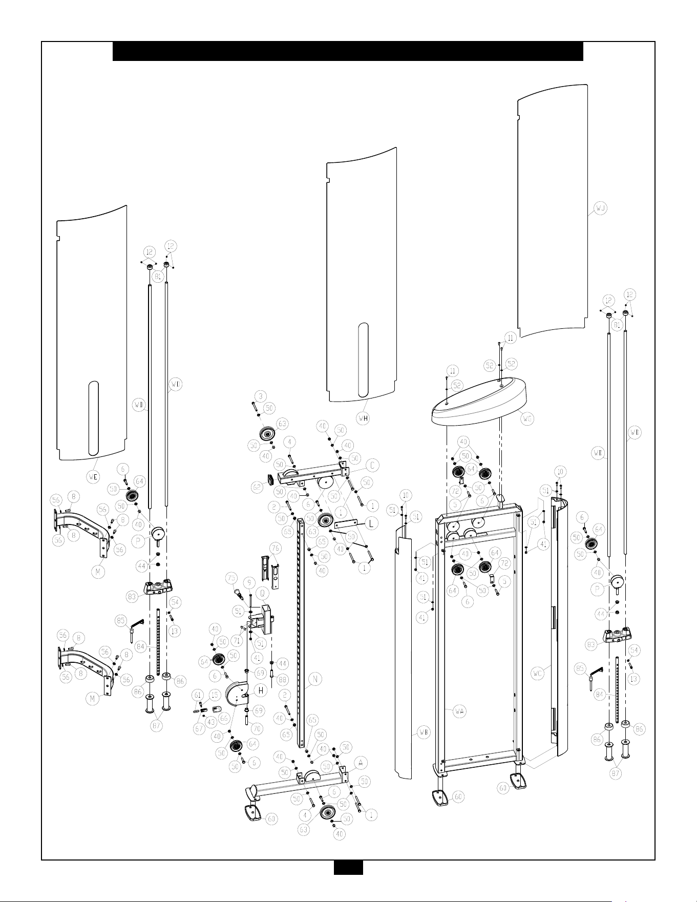
37
S2FT Exploded View (Continue)

1900S.DesPlainesAve.
ForestPark,Il60130
Phone:(708)427-3555
Fax:(708)427-3556
Hours:M-F8:30-5:00CST
www.bodysolid.com
Copyright 2009. Body-Solid. All rights reserved. Body-Solid reserves the right to change design and specications when we feel it will improve the product.
Body-Solid machines maintain several patented and patent pending features and designs. All rights reserved on all design patents and utility patents.
PLEASE WRITE YOUR SERIAL NUMBER IN THE BOXES BELOW
S/N#
011878-��-��-����-����
S2FT