


I m p o r t a n t S a f e t y I n s t r u c t i o n s
4
Before beginning any fitness program, you should obtain a complete physical examination from your physician.
Il est conseille de subir un examen medical complet avant d’entreprendre tout programme d’exercise.
Si vous avez des etourdissements ou des faiblesses, arretez les exercices immediatement.
Antes de comenzar cualquier programma de ejercicios, deberias tener un examen fisico con su doctor.
When using exe rc ise e quipme nt, you
should alw ays t ake ba sic prec aut ions,
including the follow ing:
m Read all instructions before using the GDCC250.
These instructions are written to ensure your safety
and to protect the unit.
m Do not allow children on or near the equipment.
m Use the equipment only for its intended purpose
as described in this guide. Do not use accessory
attachments that are not recommended by the
manufacturer. Such attachments might cause
injuries.
m Wear proper exercise clothing and shoes for your
workout, no loose clothing.
m Use care when getting on or off the unit.
m Do not overexert yourself or work to exhaustion.
m If you feel any pain or abnormal symptoms, stop
your workout immediately and consult your
physician.
m Never operate the unit when it has been dropped or
damaged. Return the equipment to a service
center for examination and repair.
m Never drop or insert objects into any opening in
the equipment.
m Always check the unit before each use. Make sure
that all fasteners are secure and in good working
condition.
m Do not use the equipment outdoors or near water.
Persona l Safet y During Asse mbly
m It is strongly recommended that a qualified dealer
assemble the equipment.
Assistance is required.
m Before beginning assembly, please take the time
to read the instructions thoroughly.
m Read each step in the assembly instructions and
follow the steps in sequence. Do not skip ahead.
If you skip ahead, you may learn later that you
have to disassemble components and that you
may have damaged the equipment.
m Assemble and operate the GDCC250 on a solid,
level surface. Locate the unit a few feet from the
walls or furniture to provide easy access.
The GDCC250 is designed for your enjoyment. By follow-
ing these precautions and using common sense, you will
have many safe and pleasurable hours of healthful exer-
cise with your Body-Solid GDCC250.
After assembly, you should check all functions to ensure
correct operation. If you experience problems, first re-
check the assembly instructions to locate any possible
errors made during assembly. If you are unable to correct
the problem, call the dealer from whom you purchased
the machine or call 1-800-556-3113 for the dealer near-
est you.
Obta ining Ser vice
Please use this Owner’s Manual to make sure that all
parts have been included in your shipment. When order-
ing parts, you must use the part number and description
from this Owner’s Manual. Use only Body-Solid replace-
ment parts when servicing this unit. Failure to do so will
void your warranty and could result in personal injury.
For information about product operation or service, check
out the official Body-Solid website at www.bodysolid.com
or contact an authorized Body-Solid dealer or a Body-Solid
factory-authorized service company or contact Body-Solid
customer service at one of the following:
Toll Free: 1-800-556-3113
Phone:
1-708-427-3555
Fax:
1-708-427-3556
Hours: M-F 8:30-5:00 CST
E-Mail: [email protected]
Or write to: Body-Solid, Inc.
Service Department
1900 S. Des Plaines Ave.
Forest Park, IL 60130 USA
Reta in this Ow ne r’s Ma nual for fut ure re fer-
enc e. Par t num bers are required w he n order-
ing re plac em ent par ts.

P r e p a r a t i o n s
6
CAU TION : To set up t his unit, you w ill need a ssist a nce . Do not at t em pt assem bly by yourself.
You must review and follow the instructions in this Owner’s Manual. If you do not assemble and use the GDCC250
according to these guidelines, you could void the Body-Solid warranty.
Require d Tools
The basic tools that you must obtain before assembling
the GDCC250 include but are not limited to:
m Standard Wrench Set
m Metric Wrench Set
m Adjustable Wrench
Inst allat ion Require me nts
Follow these installation requirements when assembling
the GDCC250:
Set up the GDCC250 on a solid, flat surface. A smooth,
flat surface under the machine helps keep it level. A level
machine has fewer malfunctions.
Provide ample space around the machine. Open space
around the machine allows for easier access.
Insert all bolts in the same direction. For aesthetic purpos-
es, insert all bolts in the same direction unless specified
(in text or illustrations) to do otherwise.
Leave room for adjustments. Tighten fasteners such as
bolts, nuts, and screws so the unit is stable, but leave
room for adjustments. Do not fully tighten fasteners until
instructed in the assembly steps to do so.
Fill out and mail the warranty card.
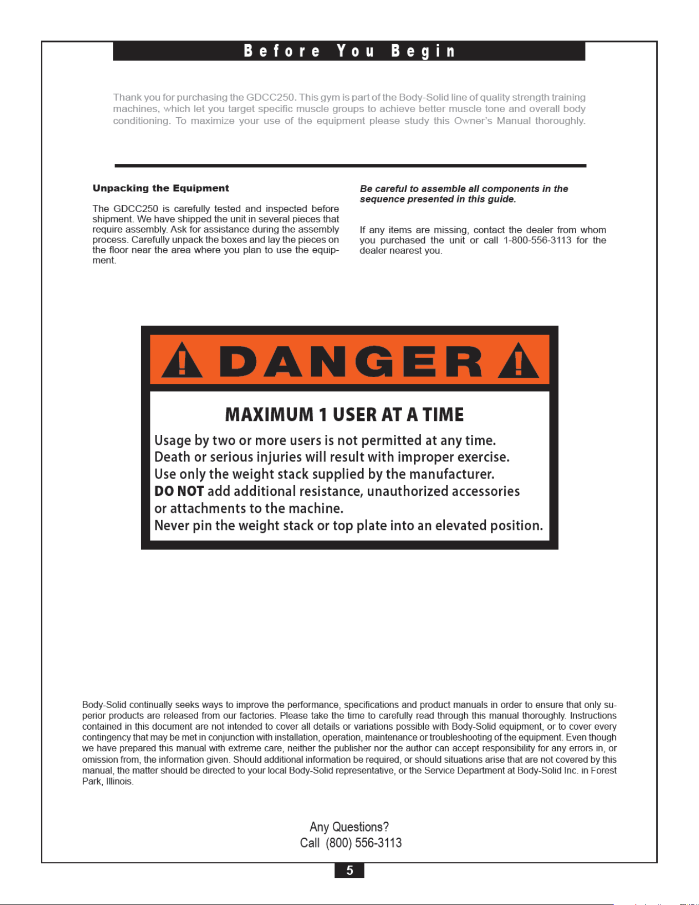
Be careful to assemble components in the sequence
presented in this guide.
NOTE: With so many assembled parts, proper
alignment and adjustment is critical. While
tightening the nuts and bolts, be sure to leave
room for adjustments.
CAUTION: Obtain assistance! Do not attempt to
assemble the GDCC250 by yourself.
Review the Installation Requirements
before proceeding with the following
steps.
7
A s s e m b l y I n s t r u c t i o n s
Assembly of the GDCC250 takes professional installers about 2 hours to complete. If this is the first time you have
assembled this type of equipment, plan on significantly more time.
Profe ssiona l inst allers a re highly re comm ended!
However, if you acquire the appropriate tools, obtain assistance, and follow the assembly steps sequentially,
the process will take time, but is fairly easy.
Assem bly T ips
Read all “Notes” on each page before beginning each
step.
While you may be able to assemble the GDCC250 using
the illustrations only, important safety notes and other tips
are included in the text.
Some pieces may have extra holes that you will not use.
Use only those holes indicated in the instructions and il-
lustrations.
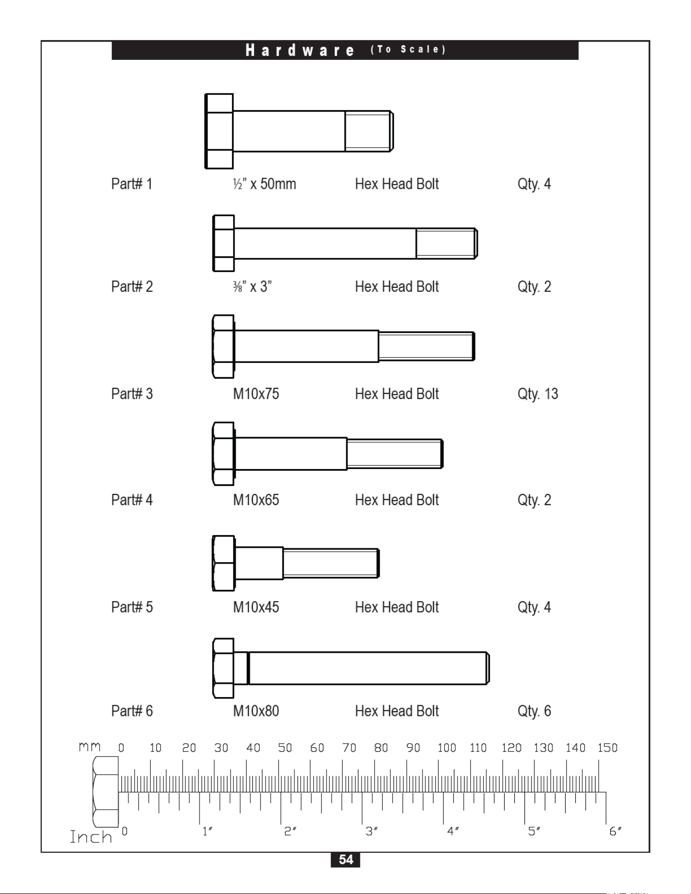
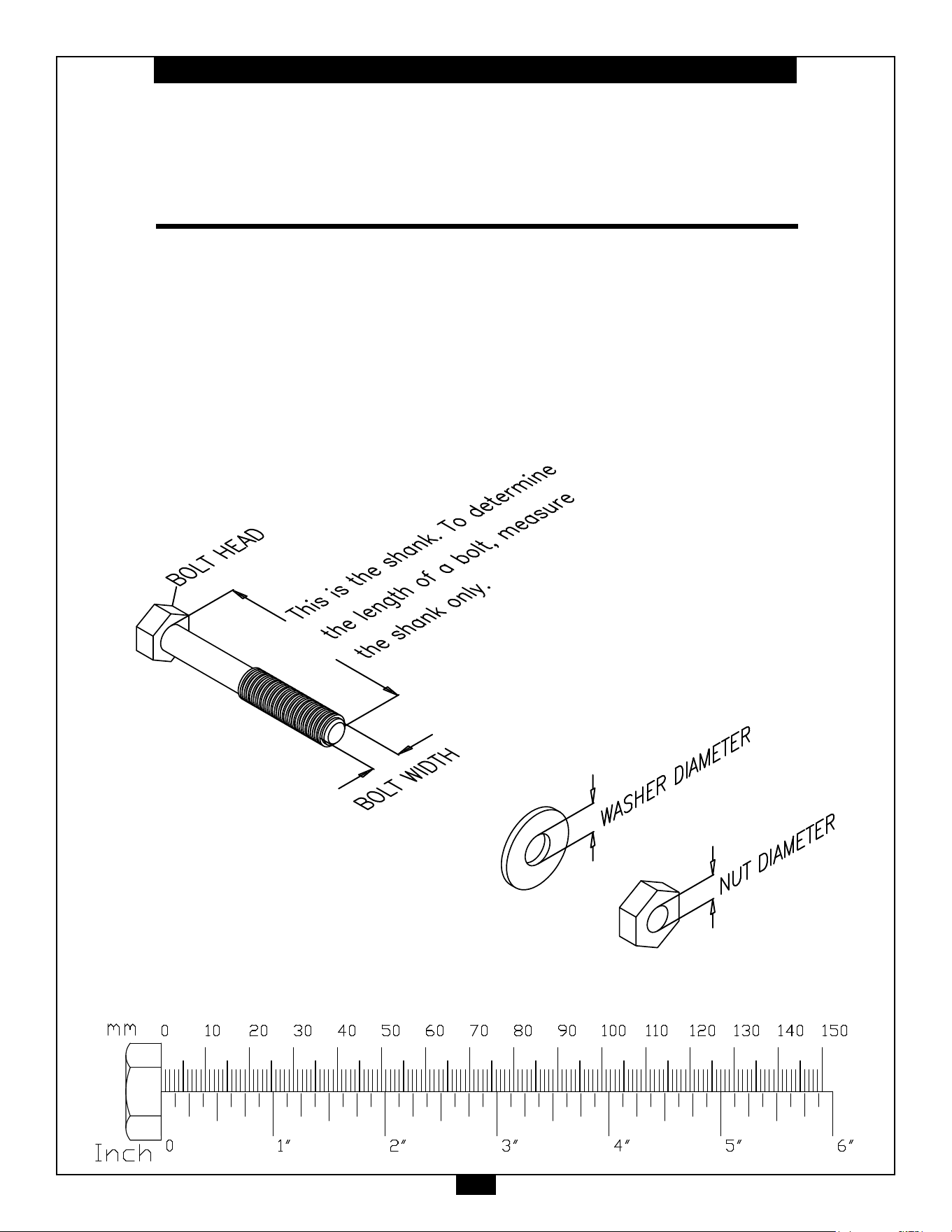
NOTE:
To find out the length of a particular bolt,
measure its shank (the long, narrow part
beneath the head). Refer to the following
diagram:
Do not fully tighten bolts until instructed to do so.
Note : Aft e r a sse m bly, you should check all functions
to ensure correc t ope ration. If you experience
problems,rstrechecktheassemblyinstructions
to loc at e any possible er rors m ade during a sse m bly.
If you are una ble to correc t the problem , c all the
dea ler from w hom you purchased the ma chine or
ca ll 1 -80 0 -55 6 -31 13 for the deale r nea re st you.
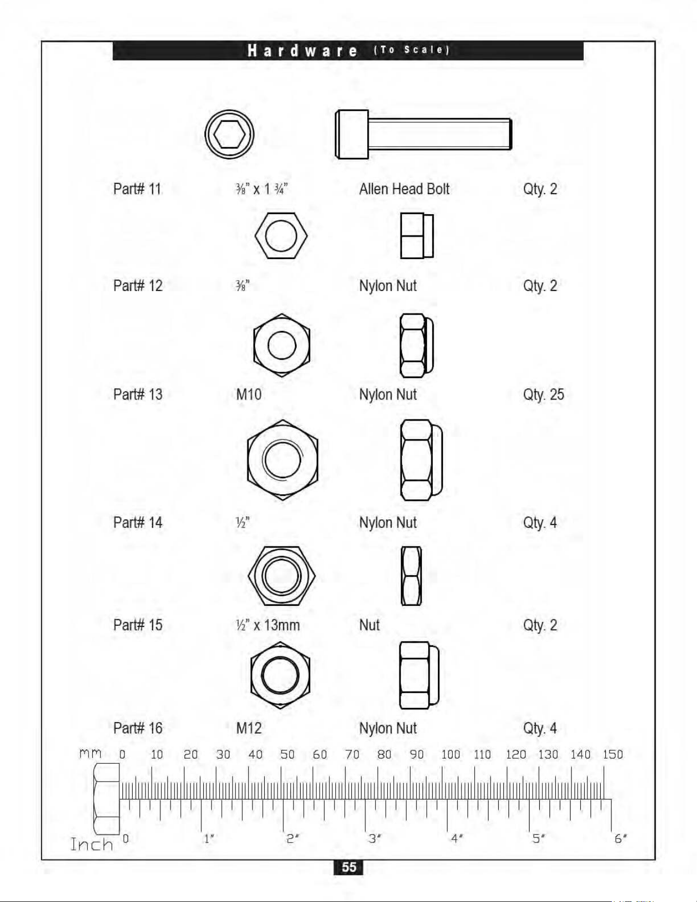
IM PORTANT!
Before you begin you should look at the quick reference
guide that shows all hardware parts (in actual size) along
with the corresponding key numbers on the assembly in-
structions.


10
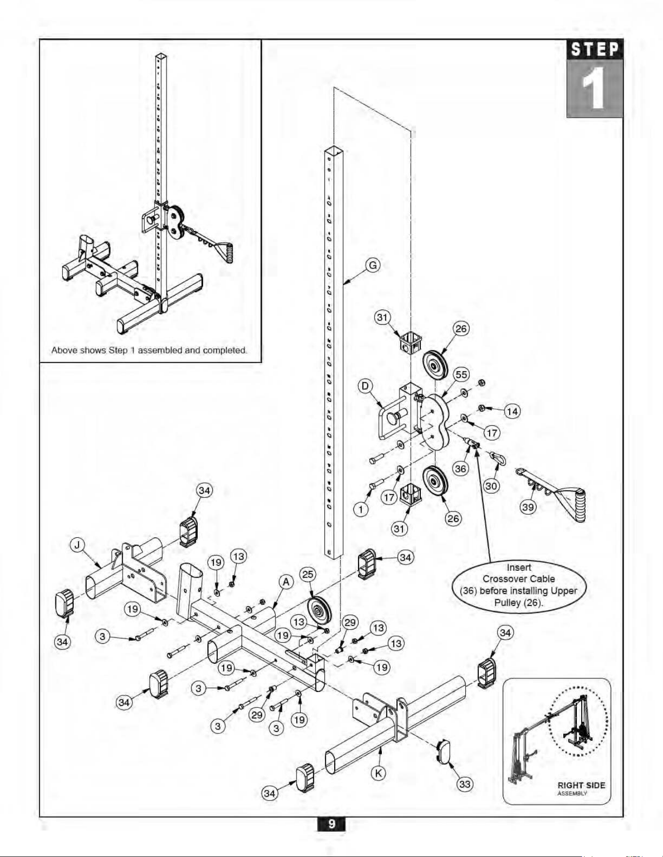
S T E P
2
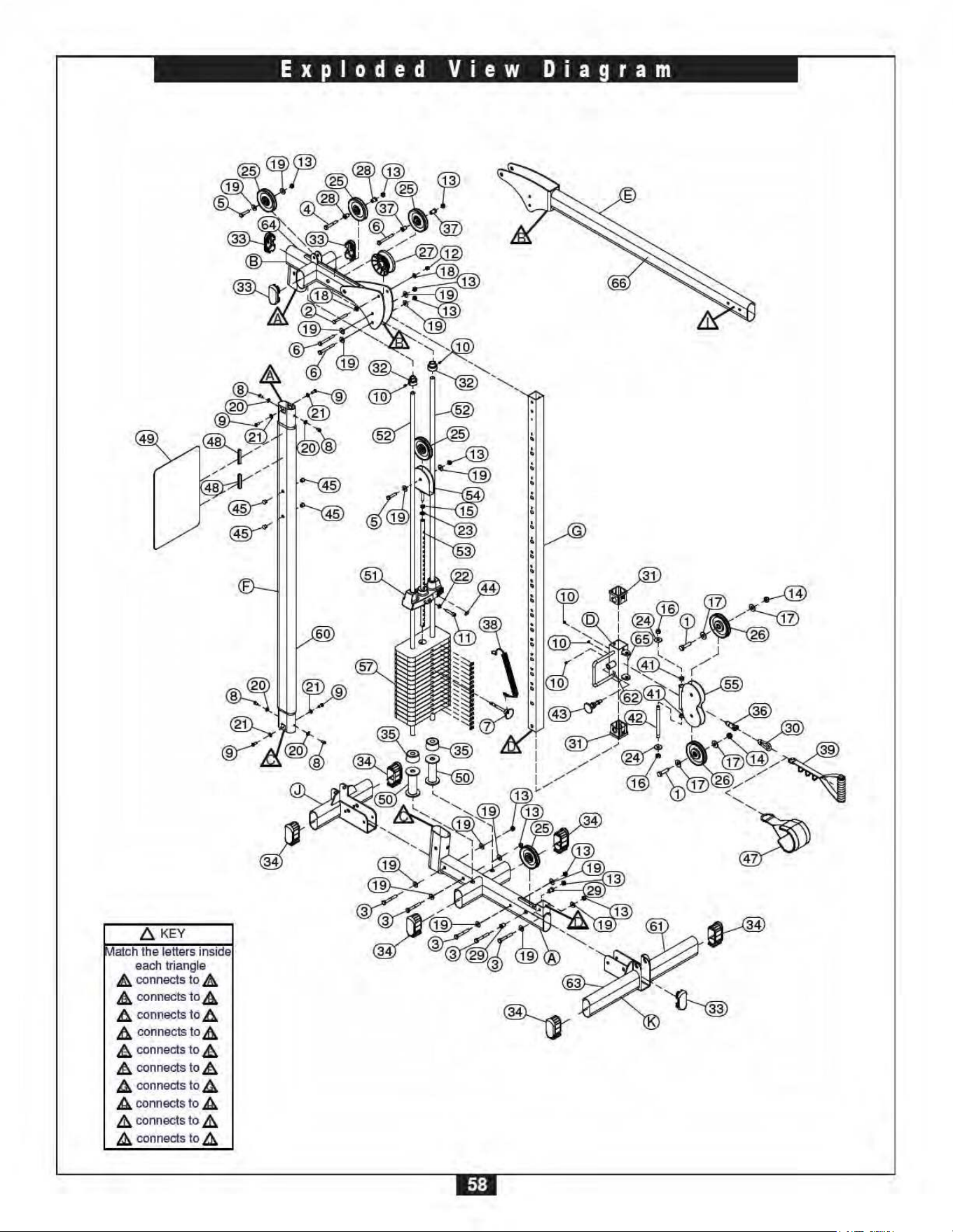
A. Insert Upright Frame (F) into Base Frame (A) and secure using:
Tw o 8 (M 8 x 1 5 hex head bolt )
Tw o 9 (M 8 x 2 0 hex head bolt )
Tw o 20 (M 8 arc w ashe r)
Tw o 21 (M 8 w ashe r)
NOTE: Pay special attention to the orientation of Upright Frame (F) as shown in the
diagram. Make sure the pre-drilled holes are positioned closest to Top Frame
(B).
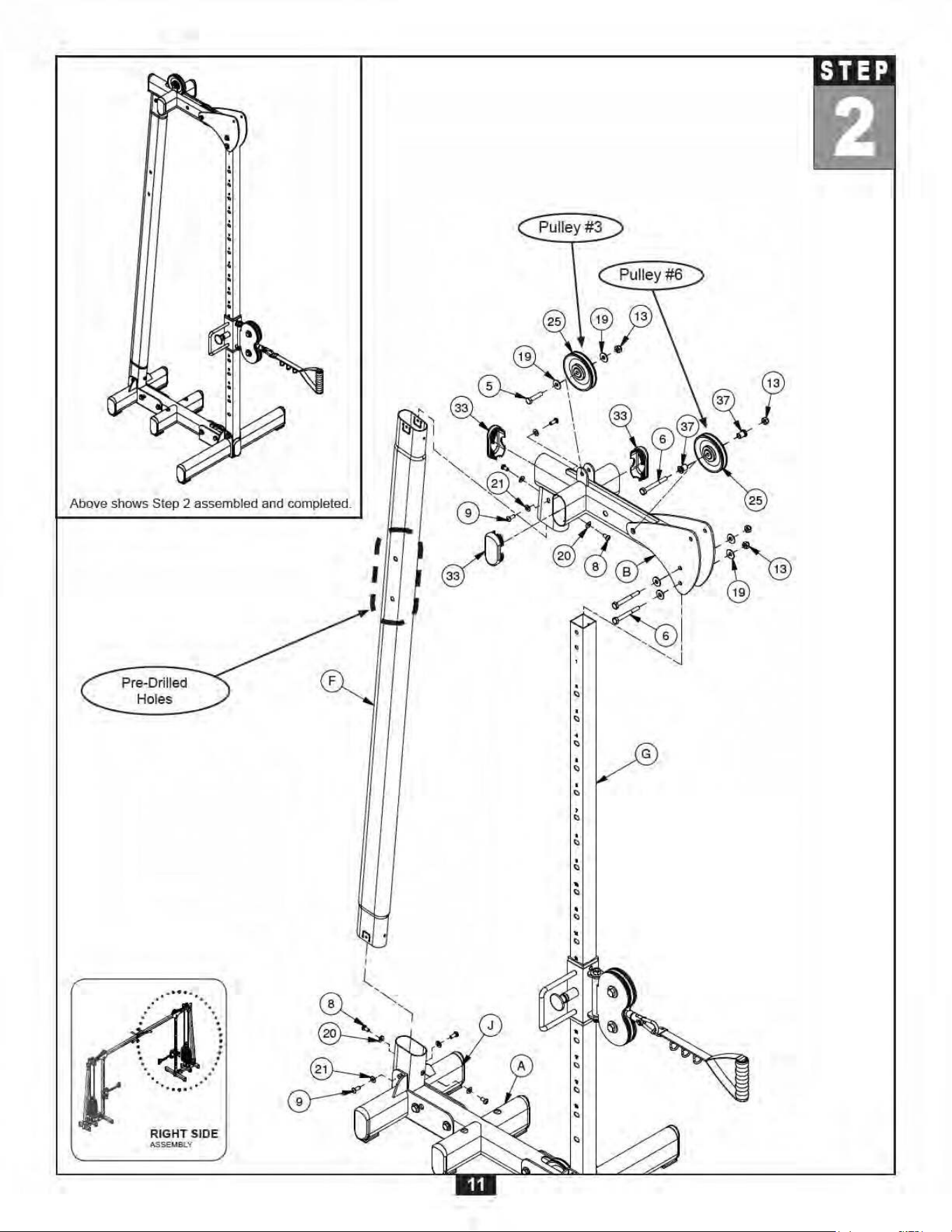
B. Insert three End Caps (33) into Top Frame (B) as shown.
C. Connect Pulley #3 (25) to Top Frame (B) using:
One 5 (M 1 0 x 4 5 hex he a d bolt)
Tw o 19 (M 1 0 w ashe r)
One 13 (M 1 0 nylon nut)
D. Connect Pulley #6 (25) to Top Frame (B) and secure using:
One 6 (M 1 0 x 8 5 hex he a d bolt)
Tw o 37 (steel bushing)
One 13 (M 1 0 nylon nut)
E. Place Top Frame (B) onto Upright Frame (F) and Guide Post (G) and secure
using:
Tw o 9 (M 8 x 2 0 hex head bolt )
Tw o 8 (M 8 x 1 5 hex head bolt )
Tw o 21 (M 8 w ashe r)
Tw o 20 (M 8 arc w ashe r)
Tw o 6 (M 1 0 x 8 0 hex head bolt )
Four 19 (M 1 0 w a sher)
Tw o 13 (M 1 0 nylon nut)
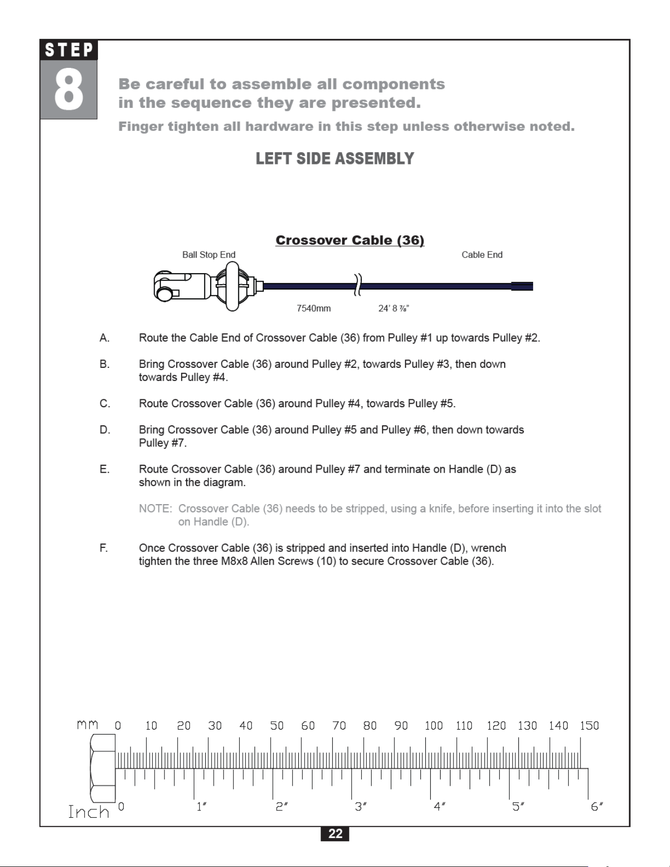
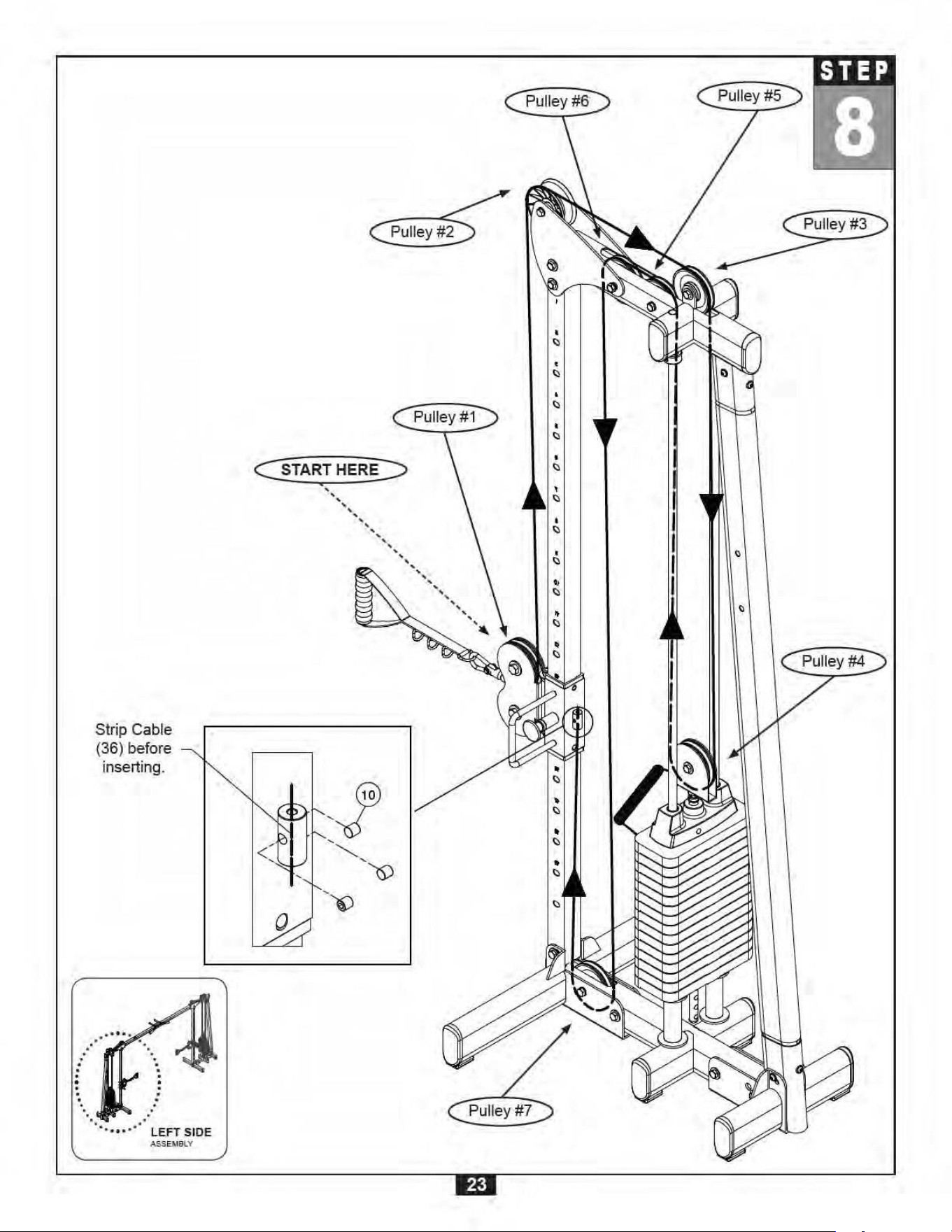
Be care ful to assemble all components
in the sequence they are pre se nt e d.
Finge r tight en a ll ha rdw are in this st ep unle ss ot he rw ise not ed.
RIGH T SIDE ASSEM BLY

12
S T E P
3
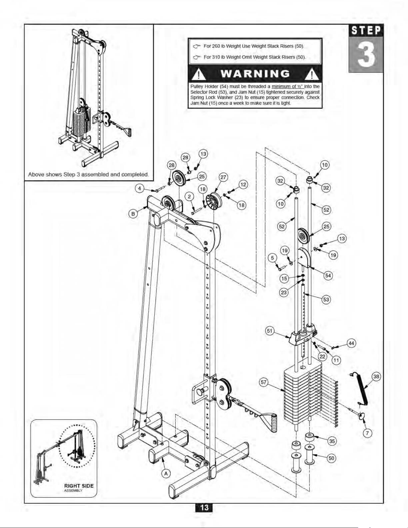
A. Insert Pulley (25) into Top Frame (B) and secure using:
One 4 (M 1 0 x 6 5 hex he a d bolt)
One 13 (M 1 0 nylon nut)
Tw o 28 (steel bushing)
B. Insert Pulley (27) into Top Frame (B) and secure using:
One 2 (3 /8 ” x 3” hex head bolt )
Tw o 18 (3 /8 ” w ashe r)
One 12 (3 /8 ” nylon nut)
C. Place both Weight Stack Risers (50) onto Base Frame (A) as shown in the diagram.
NOTE: Weight Stack Risers are omitted when using the upgrade 310 Lb Weight Stack.
D. Place a Rubber Donut (35) onto each Weight Stack Riser (50) or onto Base Frame (A) if Weight
Stack Risers (50) have been omitted.
E. Slide both Guide Rods (52) through Rubber Donuts (35) and Weight Stack Risers (50) and into
Base Frame (A). If Weight Stack Risers (50) have been omitted, slide both Guide Rods (52)
through Rubber Donuts (35) and into Base Frame (A).
F. Slide Weight Stack Plates (57) onto Guide Rods (52) one at a time.
G. Connect Selector Bar (53) to Top Plate (51) using:
One 11 (3 /8 ” x 1 3/4” a llen he a d bolt)
One 22 (3 /8 ” spring w a sher)
H. Thread Pulley Holder (54) into Selector Bar (53) a minimum of ½” using:
One 15 (½ ” nut )
One 23 (½ ” spring w ashe r)
I. Slide Pulley (25) into Pulley Holder (54) and secure using:
One 5 (M 1 0 x 4 5 hex he a d bolt)
Tw o 19 (M 1 0 w ashe r)
One 13 (M 1 0 nylon nut)
J. Slide the Top Plate Assembly just constructed onto Guide Rods (52).
K. Slide Shaft Collars (32) onto Guide Rods (52).
L. Bring Guide Rods (52) toward the pre-drilled holes on Top Frame (B) and secure by pushing
Shaft Collar (32) upwards into the hole. Turn to lock Shaft Collars (32) in place then secure by
tightening M8x8 Allen Screws (10). Make sure Guide Rods (52) are completely secured.
M. Connect Weight Stack Pin (7) to Weight Stack Pin Lanyard (38) and then secure Weight Stack
Pin (7) to Weight Stack (57) at any position.
N. Apply Weight Stack Stickers (44) onto Weight Stack (57) as shown in the diagram starting with
the application of sticker 1 onto Top Plate (51).
Be care ful to assemble all components
in the sequence they are pre se nt e d.
Finge r tight en a ll ha rdw are in this st ep unle ss ot he rw ise not ed.
RIGH T SIDE ASSEM BLY


18
S T E P
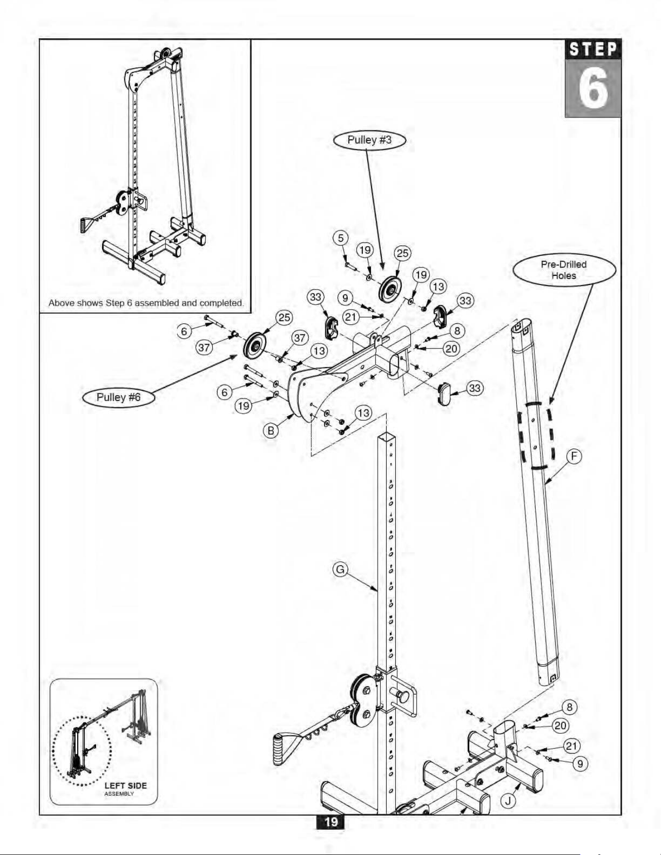
6
Be care ful to assemble all components
in the sequence they are pre se nt e d.
Finge r tight en a ll ha rdw are in this st ep unle ss ot he rw ise not ed.
LEFT SI DE ASSEMBLY
A. Insert Upright Frame (F) into Base Frame (A) and secure using:
Tw o 8 (M 8 x 1 5 hex head bolt )
Tw o 9 (M 8 x 2 0 hex head bolt )
Tw o 20 (M 8 arc w ashe r)
Tw o 21 (M 8 w ashe r)
NOTE: Pay special attention to the orientation of Upright Frame (F) as shown in the
diagram. Make sure the pre-drilled holes are positioned closest to Top Frame
(B).
B. Insert three End Caps (33) into Top Frame (B) as shown.
C. Connect Pulley #3 (25) to Top Frame (B) using:
One 5 (M 1 0 x 4 5 hex he a d bolt)
Tw o 19 (M 1 0 w ashe r)
One 13 (M 1 0 nylon nut)
D. Connect Pulley #6 (25) to Top Frame (B) and secure using:
One 6 (M 1 0 x 8 5 hex he a d bolt)
Tw o 37 (2 6 .5mm st e e l bushing)
One 13 (M 1 0 nylon nut)
E. Place Top Frame (B) onto Upright Frame (F) and Guide Post (G) and secure
using:
Tw o 9 (M 8 x 2 0 hex head bolt )
Tw o 8 (M 8 x 1 5 hex head bolt )
Tw o 21 (M 8 w ashe r)
Tw o 20 (M 8 arc w ashe r)
Tw o 6 (M 1 0 x 8 0 hex head bolt )
Four 19 (M 1 0 w a sher)
Tw o 13 (M 1 0 nylon nut)

20
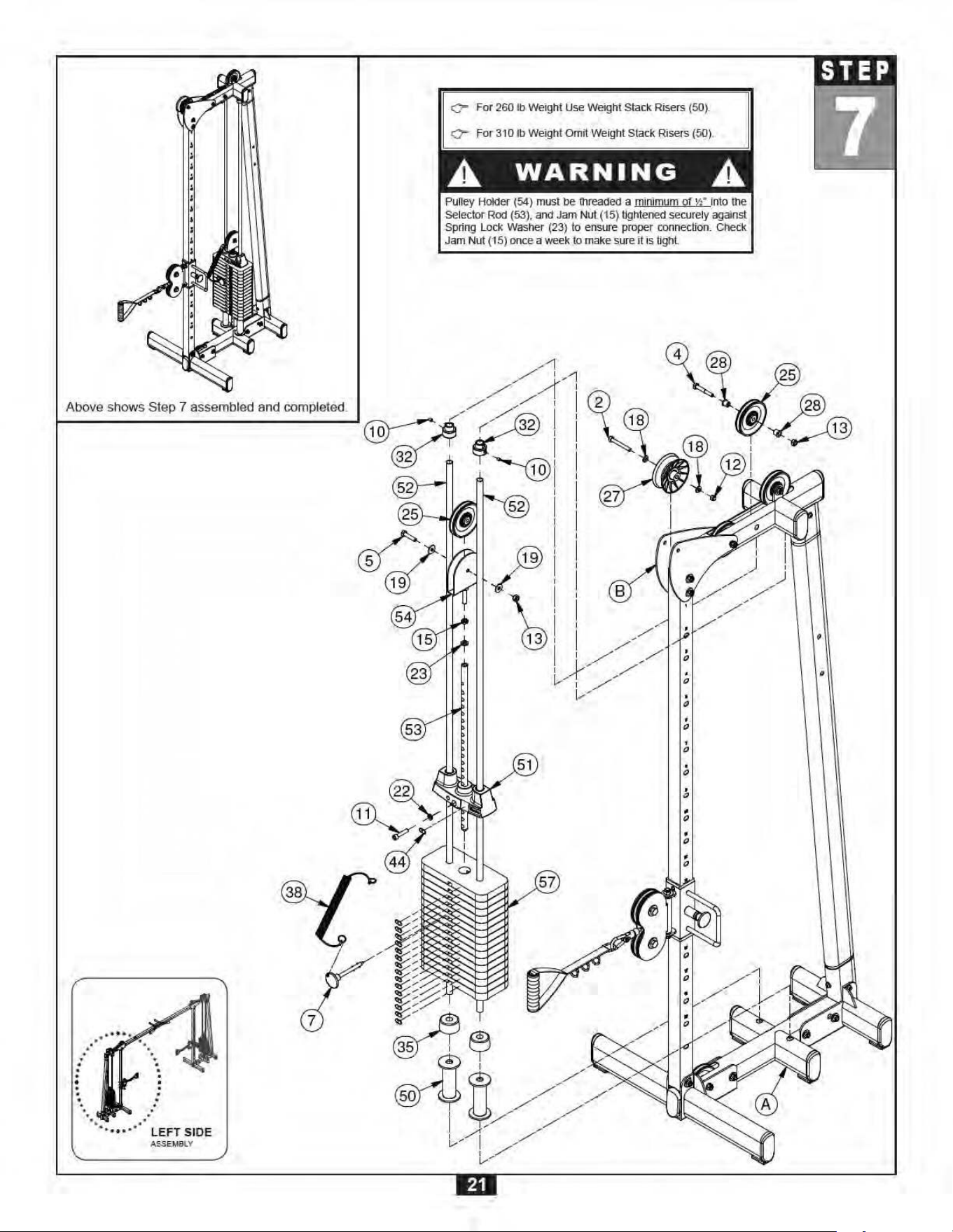
S T E P
7
Be care ful to assemble all components
in the sequence they are pre se nt e d.
Finge r tight en a ll ha rdw are in this st ep unle ss ot he rw ise not ed.
LEFT SI DE ASSEMBLY
A. Insert Pulley (25) into Top Frame (B) and secure using:
One 4 (M 1 0 x 6 5 hex he a d bolt)
One 13 (M 1 0 nylon nut)
Tw o 28 (steel bushing)
B. Insert Pulley (27) into Top Frame (B) and secure using:
One 2 (3 /8 ” x 3” hex head bolt )
Tw o 18 (3 /8 ” w ashe r)
One 12 (3 /8 ” nylon nut)
C. Place both Weight Stack Risers (50) onto Base Frame (A) as shown in the diagram.
NOTE: Weight Stack Risers are omitted when using the upgrade 310 Lb Weight Stack.
D. Place a Rubber Donut (35) onto each Weight Stack Riser (50) or onto Base Frame (A) if Weight
Stack Risers (50) have been omitted.
E. Slide both Guide Rods (52) through Rubber Donuts (35) and Weight Stack Risers (50) and into
Base Frame (A). If Weight Stack Risers (50) have been omitted, slide both Guide Rods (52)
through Rubber Donuts (35) and into Base Frame (A).
F. Slide Weight Stack Plates (57) onto Guide Rods (52) one at a time.
G. Connect Selector Bar (53) to Top Plate (51) using:
One 11 (3 /8 ” x 1 3/4” a llen he a d bolt)
One 22 (3 /8 ” spring w a sher)
H. Thread Pulley Holder (54) into Selector Bar (53) a minimum of ½” using:
One 15 (½ ” nut )
One 23 (½ ” spring w ashe r)
I. Slide Pulley (25) into Pulley Holder (54) and secure using:
One 5 (M 1 0 x 4 5 hex he a d bolt)
Tw o 19 (M 1 0 w ashe r)
One 13 (M 1 0 nylon nut)
J. Slide the Top Plate Assembly just constructed onto Guide Rods (52).
K. Slide Shaft Collars (32) onto Guide Rods (52).
L. Bring Guide Rods (52) toward the pre-drilled holes on Top Frame (B) and secure by pushing
Shaft Collar (32) upwards into the hole. Turn to lock Shaft Collars (32) in place then secure by
tightening M8x8 Allen Screws (10). Make sure Guide Rods (52) are completely secured.
M. Connect Weight Stack Pin (7) to Weight Stack Pin Lanyard (38) and then secure Weight Stack
Pin (7) to Weight Stack (57) at any position.
N. Apply Weight Stack Stickers (44) onto Weight Stack (57) as shown in the diagram starting with
the application of sticker 1 onto Top Plate (51).

24
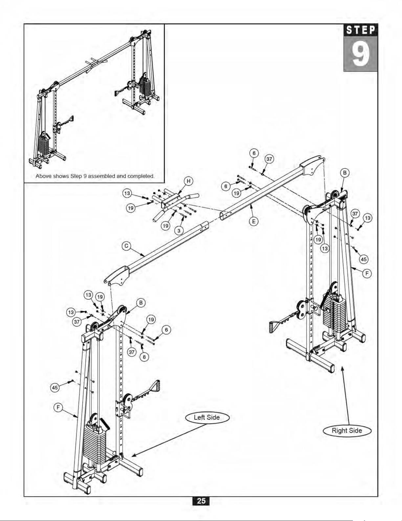
S T E P
9
A. Face the Left Side and Right Side of the GDCC250 towards each other as shown in the
diagram.
NOTE: Certain hardware may need to be removed to complete this installation.
The hardware was pre-installed to aid with finalizing the assembly.
B. Connect Cross Frame (E), Cross Frame with Insert (C) and Pull Up bar (H) using:
T hre e 3 (M 1 0 x 7 5 hex he a d bolt)
Six 1 9 (M 1 0 w a sher)
T hre e 1 3 (M 1 0 nylon nut)
C. Remove the following pre-installed hardware in order to install the Cross Frame Assembly:
Six 6 (M 1 0 x 80 hex he a d bolt)
Eight 1 9 (M10 w ashe r)
Six 1 3 (M 1 0 nylon nut)
Four 37 (2 6 .5 m m steel bushing)
D. Install the Cross Frame Assembly onto Top Frame (B) and secure using:
Six 6 (M 1 0 x 80 hex he a d bolt)
Eight 1 9 (M10 w ashe r)
Six 1 3 (M 1 0 nylon nut)
Four 37 (2 6 .5 m m steel bushing)
E. Insert four Round Cap (45) into Right Side Upright Frame (F) and four Round End Cap (45) into
Left Side Upright Frame (F).
F. Now you may wrench tighten all hardware on the unit.
Be care ful to assemble all components
in the sequence they are pre se nt e d.
Finge r tight en a ll ha rdw are in this st ep unle ss ot he rw ise not ed.


W a r n i n g , S a f e t y & M a i n t e n a n c e
30
Precision craftsmanship assures Body-Solid’s ability to
consistently deliver products of the highest standards. Our
products have been carefully designed to ensure safe, ef-
ficient long term operation.
However, it must be realized that safe use of this equip-
ment requires that owners carefully read and follow the
Body-Solid use recommendations, warnings, and mainte-
nance guidelines in this Owners Manual.
Routine inspection and maintenance is of critical impor-
tance to ensure maximum safety and performance. Body-
Solid uses the highest quality materials available, but wear
is inevitable. Therefore, you must carefully inspect your
equipment as outlined in the Maintenance Schedule.
Be advised that dangerous conditions can arise even dur-
ing a warranty period. A warranty does not negate the
owner’s responsibility to thoroughly, carefully and daily
inspect the machine.
Including maintaining the equipment, the owner’s respon-
sibility is also to:
m Be sure to always provide adequate supervision to
all end-users.
m Be sure to instruct all end-users of proper usage.
m Be sure all supervisors and personal trainers who
instruct end-users on equipment use are properly
trained and know the function and importance of
every adjustment and setting.
Also, be sure these trainers provide proper
instruction to end-users on the fundamentals of
strength training.
CABLES:
m While the machine is not in use, carefully run your
fingers along the cable to feel for thinning or bulging
areas. Replace cables immediately at the first sign of
damage or wear. Do not use equipment until
damaged cable has been replaced.
m Visually inspect the cables for fraying, cracking,
peeling or discoloration.
m Check slack in cables and re-adjust cable tension if
needed.
m Check that the jam nut on the selector rod top bolt is
tight.
UPH OLSTERY:
m Wipe down after every workout.
m Periodically take the time to use a mild soap or a
mild vinyl upholstery cleaner. Avoid using any
abrasive cleaner not intended for use on vinyl.
m Keep sharp or pointed objects out of your pockets
and clear of all upholstery.
NU TS/BOLT S/FASTEN ERS:
m Periodically inspect all nuts and bolts. Tighten if
needed. If bolts seem to loosen periodically, use
Loctite 242 for a long-term cure.
m Go through a re-tightening sequence periodically to
ensure that all hardware is properly tensioned.
GUI DE RODS:
m Wipe clean with a dust free rag. Lubricate with a
Silicon or Teflon based lubricant.
ADJU STM ENT S / LOCKIN G PIN S /
TI GHT ENI NG K NOBS:
m Check all pieces for signs of visible wear or damage.
m Check springs in Snap Links and Pop Pins for proper
tension and alignment.
m If the spring sticks or has lost its rigidity, replace it
immediately.
ANT I-SK ID SU RFACES:
m Replace if they appear worn or become slippery.
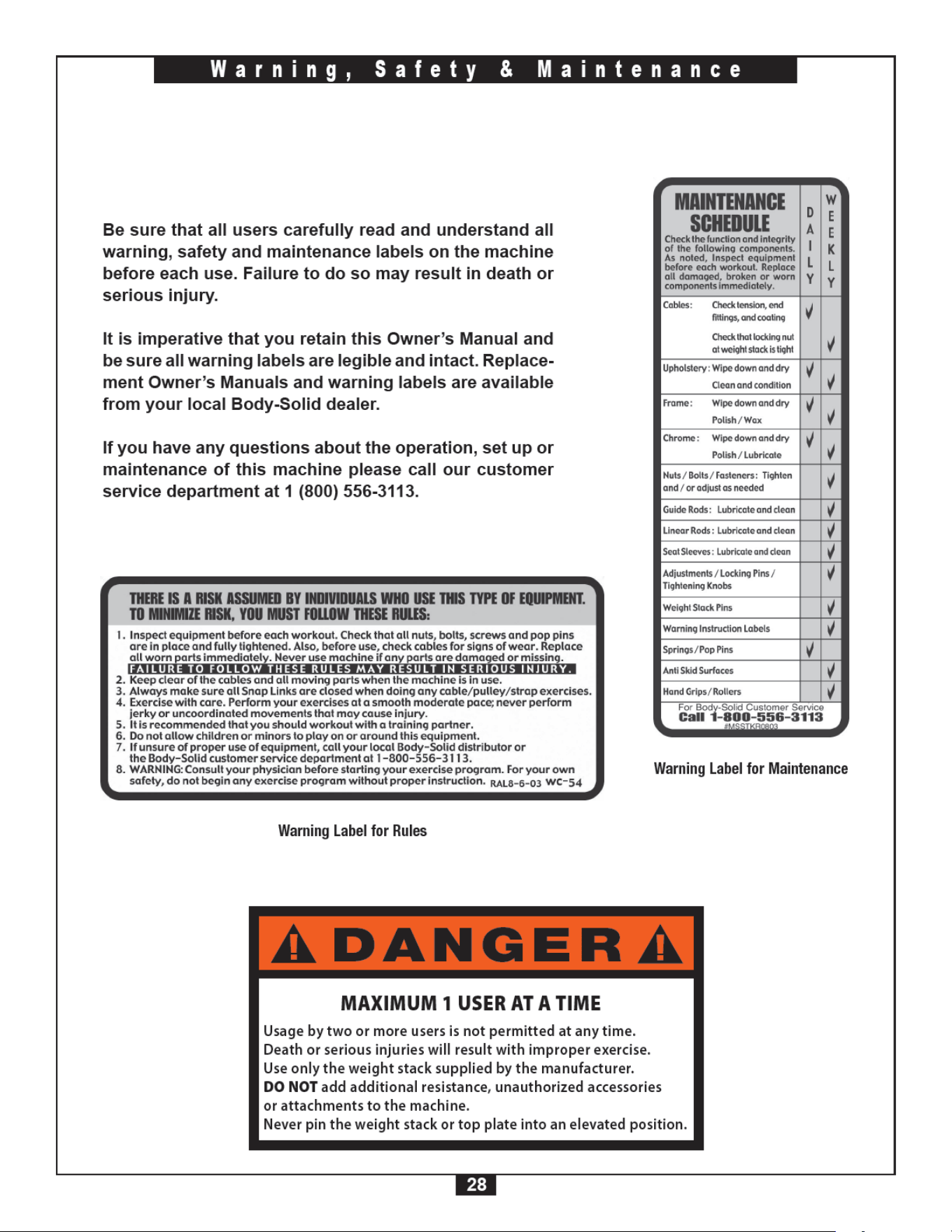
WARNI NG I NST RUCTI ON LABELS:
m Inspect and familiarize yourself with all safety
warnings and other user information on decals.


52
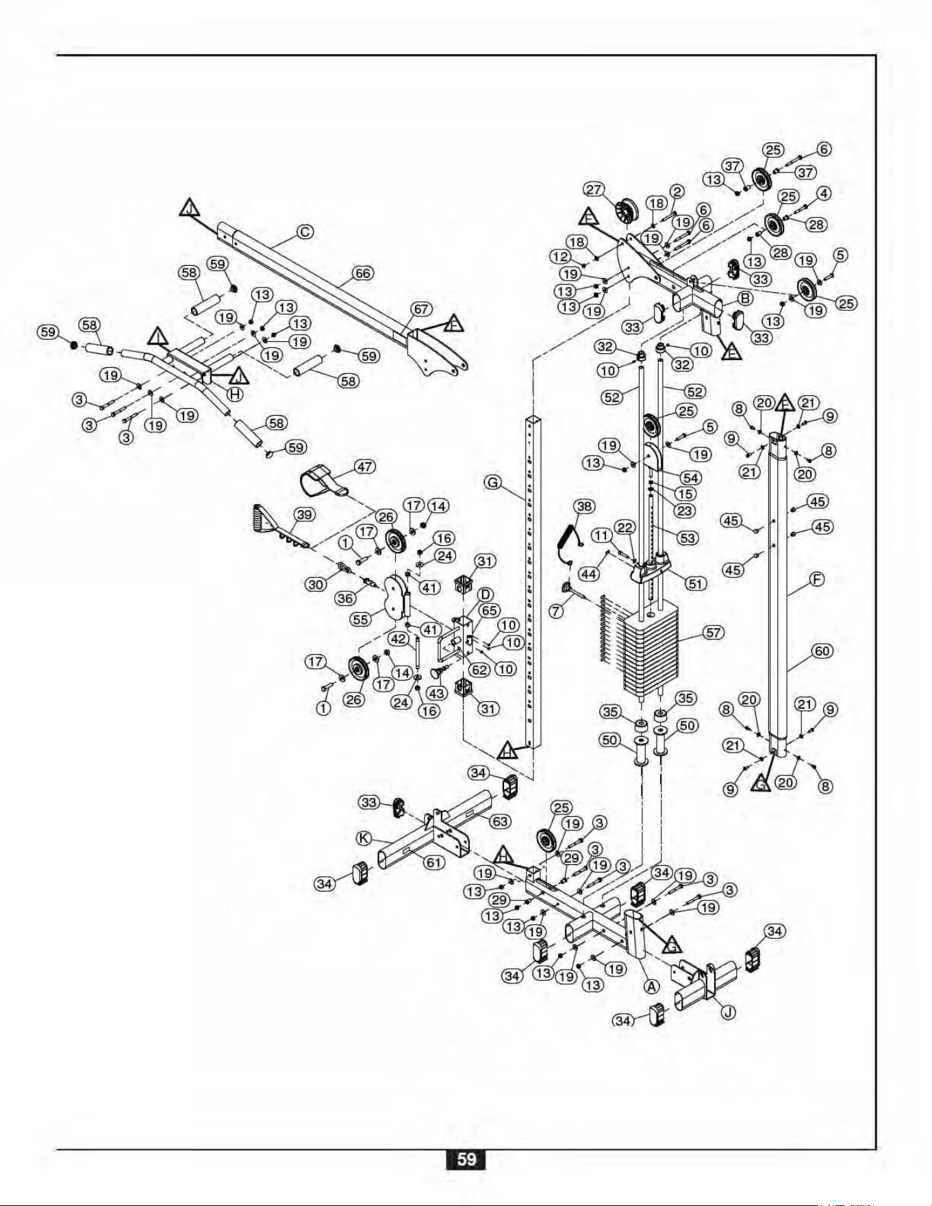
M a i n f r a m e P a r t s L i s t
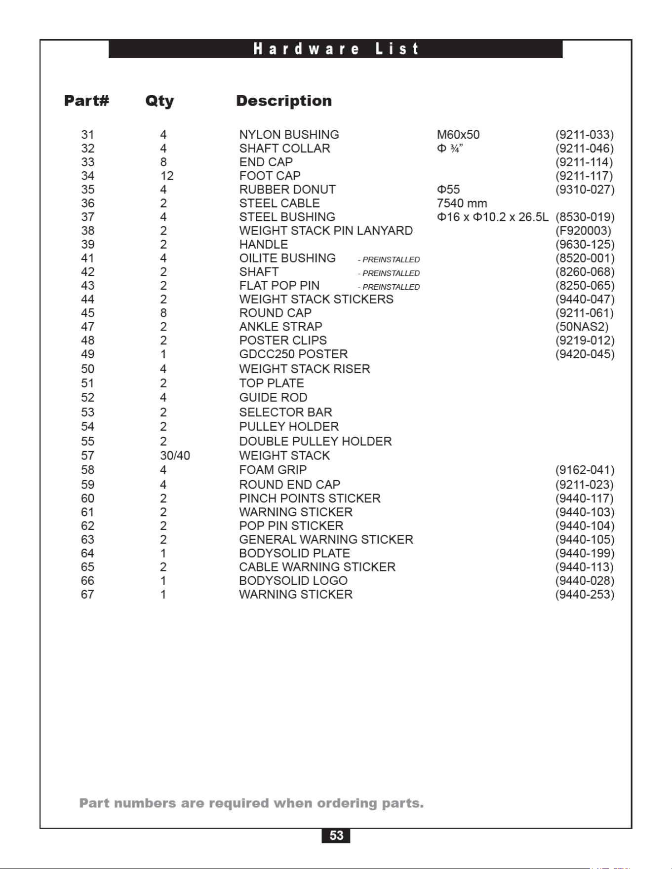
Par t num be rs a re re quired w hen orde ring pa rt s.
Part# Qt y Description
A 2 BASE FRAME
B 2 TOP FRAME
C 1 CROSS FRAME WITH INSERT
D 2 HANDLE
E 1 CROSS FRAME
F 2 UPRIGHT FRAME
G 2 GUIDE POST
H 1 PULL UP BAR
K 2 LARGE STABILIZER FRAME
J 2 SMALL STABILIZER FRAME
1 4 HEX HEAD BOLT ½” x 50 mm
2
2 HEX HEAD BOLT 3⁄8” x 3”
3
13 HEX HEAD BOLT M10x75
4
2 HEX HEAD BOLT M10x65
5
4 HEX HEAD BOLT M10x45
6
6 HEX HEAD BOLT M10x85
7
2 WEIGHT STACK PIN (8250-071)
8 8 HEX HEAD BOLT
- PREINSTALLED M8x15
9 8 HEX HEAD BOLT
- PREINSTALLED M8x20
10 10 ALLEN SCREW
- PREINSTALLED M8x8
11 2 ALLEN HEAD BOLT 3⁄8” x 1 ¾”
12
2 NYLON NUT 3⁄8”
13
25 NYLON NUT M10
14 4 NYLON NUT
½”
15
2 NUT ½” x 13 mm
16
4 NYLON NUT
- PREINSTALLED M12
17 8 WASHER ½” ID
18
4 WASHER 3⁄8” ID
19
38 WASHER M10 ID
20 8 ARC WASHER
- PREINSTALLED M8
21 8 WASHER
- PREINSTALLED M8 ID
22 2 SPRING WASHER 3⁄8”
23
2 SPRING WASHER ½”
24
4 WASHER
- PREINSTALLED M12
25 10 Pulley Φ110 (9213-002C)
26
4 Pulley Φ4½
(9213-010B)
27 2 Pulley Φ109 (9213-022A)
28 4 SteelBuShing Φ16
xΦ10
x 16.5L (8530-009)
29 4 STEEL BUSHING
Φ20xΦ10x 21.5L (8530-010)
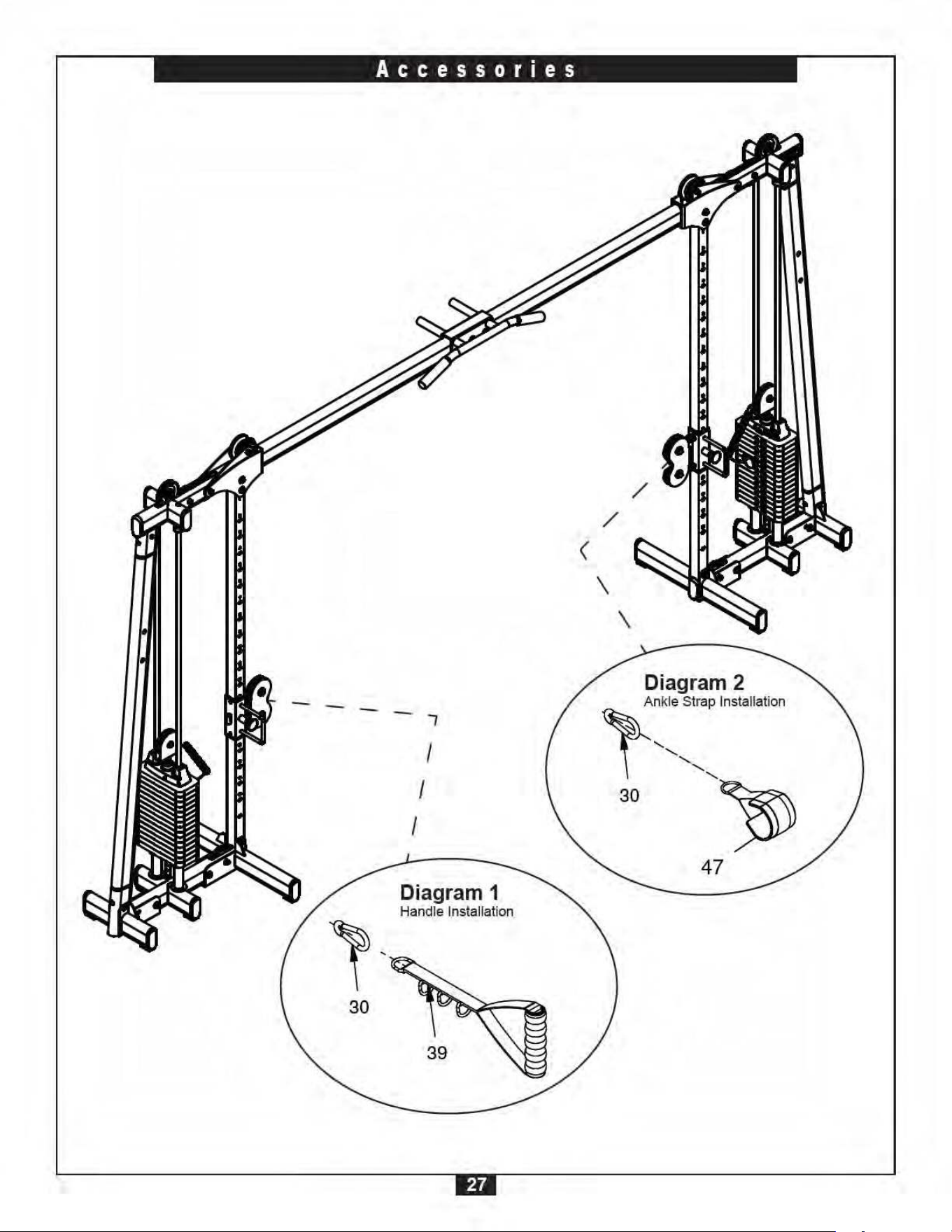
30 2 SnAPlink Φ8 (8810-001)
H a r d w a r e L i s t