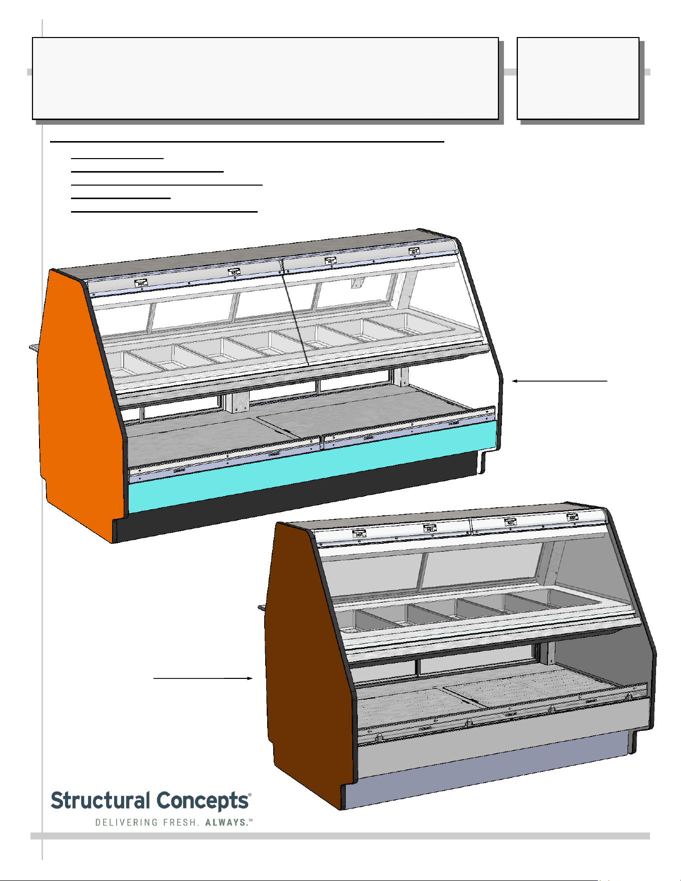
SERVICE/SELF-SERVICE HEATED COMBINATION MERCHANDISER:
> THERMOSTATS: STRUCTURAL CONCEPTS THERMOSTATS
> SERVICE HEATED UPPER: PANS
> SELF-SERVICE HEATED LOWER: DECK
> UPPER SECTION: CERAMIC OVERHEAD HEATERS AND CERAMIC METAL HALIDE LAMPS
> UPPER AND LOWER SECTIONS: HEATER ROD SYSTEM / SLIDING, REMOVABLE DOORS
USER MANUALS\21-04572_FUSION_USER MANUAL_GCD(L)(H)HHLB_HTD_SVC_SELF-SVC_COMBO CASE REV E DATE: 09/21/2023
SCC P/N
21-04572
USER
MANUAL
FUSION
CAREFULLY FOLLOW THESE INSTRUCTIONS
Model
GCD656HHLB
Model
GCD856HHLB
Structural Concepts Corp. ∙ 888 E. Porter Rd ∙ Muskegon, MI 49441 Phone: 231.798.8888 Fax: 231.798.4960 ∙ www.structuralconcepts.com
2
TABLE OF CONTENTS / MODEL LENGTH, DEPTH & HEIGHT
TABLE OF CONTENTS ...………………………………………………………………………………………..
OVERVIEW / TYPE / COMPLIANCE / WARNINGS / PRECAUTIONS / WIRING DIAGRAM / PLUGS .
INSTALLATION: REMOVAL FROM PALLET / REMOVING & REPLACING TOE-KICKS ..…………...
INSTALLATION, CONT’D: IMPORTANT! HEATED SHELF “DANGER - HOT” LABEL
PLACEMENT ………………………………………………………………………………………...…..
CASE OVERVIEW: HEATED PANS, FRONT GLASS, END PANEL, DECKS, TOE-KICK ...……..…..
CASE OVERVIEW, CONT’D: UPPER/LOWER SECTION REAR SLIDING DOORS,
THERMOSTATS, ETC………………………………………………………………………………......
CASE OVERVIEW, CONT’D: CERAMIC HEATERS / CERAMIC METAL HALIDE LAMPS …………..
CASE OVERVIEW, CONT’D: FIELD ACCESS WIRING / SWITCHES / THERMOMETER /
THERMOSTATS ………………………………………………………………………………………...
CASE OVERVIEW, CONT’D: HEATER ROD ASSEMBLIES (UPPER SECTION) ……………………...
CASE OVERVIEW, CONT’D: HEATER ROD ASSEMBLIES (LOWER DECK) ………………………….
CASE OPERATION: MAIN POWER / LIGHTS / THERMOSTATS / OPERATING TIPS / SHUTDOWN ...
CASE OPERATION, CONT’D: CERAMIC METAL HALIDE LIGHT FIXTURES ………………………...
MAINTENANCE: UPPER AND LOWER REAR SLIDING DOORS / LED LIGHT FIXTURES ………….
MAINTENANCE, CONT’D: FRONT GLASS ALIGNMENT & ADJUSTMENT / CLAMSHELL …………
MAINTENANCE, CONT’D: CUTTING BOARD/ REAR LEDGE REMOVAL ……………………………..
CLEANING SCHEDULE - TO BE PERFORMED BY STORE PERSONNEL (INTERIOR) ….…………..
CLEANING SCHEDULE - TO BE PERFORMED BY STORE PERSONNEL (EXTERIOR) ..…………...
TROUBLESHOOTING - GENERAL ISSUES ………………….……………………..…………...……….....
SERIAL LABEL INFORMATION & LOCATION ..…………………………………...…....……………....….
PROGRAMMABLE CONTROLLER (SELECT, CLICK ON OR SCAN QR CODE FOR INFO ………...
TECHNICAL SERVICE CONTACT INFORMATION / WARRANTY INFORMATION ....…………..........
2
3-4
5
6
7
8
9
10
11
12
13
14
15
16
17
18
19
20-21
22
23
24
3
OVERVIEW
• These Structural Concepts cases should be installed and
operated according to these instructions to ensure proper
performance. Improper use will void warranty.
• This unit is designed to display products in ambient store
conditions with a maximum temperature of 80 °F (27 °C) .
DRY HEAT PURPOSES / PRE-HEATING PRODUCT, ETC.
This case is designed for dry heating operations throughout the
product area. Heat is generated from heated shelving/deck.
• Structural Concepts® heated merchandisers are designed
for packaged foods at 140 °F to 165 °F (60 °C to 74 °C).
• Product must be pre-heated to these temperatures PRIOR
TO being places in merchandiser. This case is NOT
designed to heat product from cold or ambient conditions.
• This merchandiser is designed to display perishable,
packaged products. Improper use will void warranty.
• Depending upon model, overhead incandescent lamps
may be used on shelving and header of merchandiser.
COMPLIANCE
This equipment MUST be installed in compliance with
all applicable NEC, federal, state and local
electrical and plumbing codes.
WARNING
Shelves and decks are hot!
Disconnect and allow to cool 45 minutes before cleaning,
servicing or removing from case.
WARNING
HOT
SURFACE
OVERVIEW / TYPE / COMPLIANCE / WARNINGS / PRECAUTIONS / WIRING / PLUGS - PAGE 1 of 2
INTEGRATED AVERAGE PRODUCT TEMPERATURE
• These units are designed to merchandise product at an
integrated average product temperature of 150 °F (66 °C).
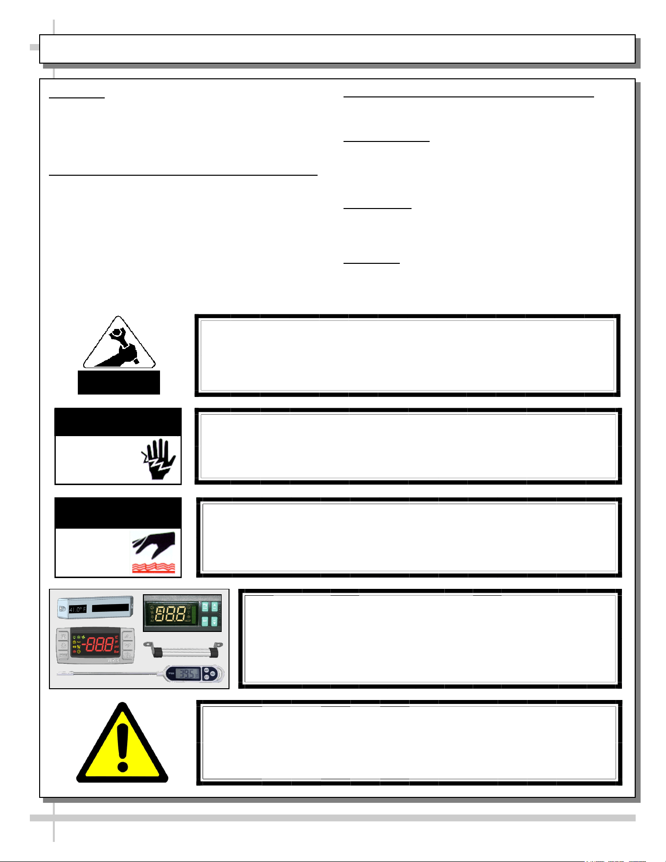
THERMOMETERS
• Thermometers in equipment reflect internal air temperature
only (not actual food temperature).
• Use probe thermometers to determine actual product
temperatures.
COMPLIANCE
• Performance issues when in violation of applicable NEC,
federal, state and local electrical and plumbing codes are
not covered by warranty. Please see below.
WARNINGS
• This page contains important warnings to prevent injury or
death. Please read carefully!
ATTENTION
CONTRACTORS
WARNING
This product can expose you to chemicals, including
Urethane (Ethyl Carbamate), which are known to the state of
California to cause cancer and birth defects or other reproductive
harm. For more information go to P65Warnings.ca.gov.
WARNING
Risk of electric shock.
Disconnect ALL ELECTRICAL SOURCES before servicing.
WARNING
ELECTRICAL
HAZARD
CAUTION! DO NOT RELY ON THERMOMETERS OR
THERMOSTATS FOR PRODUCT (FOOD) TEMPERATURES.
• Thermometers & thermostats reflect air temperatures ONLY.
• For ACTUAL product (food) temperatures, use a calibrated food
probe thermometers ONLY.
• For accurate readings, DO NOT use infrared food thermometers.
4
CAUTION! LAMP REPLACEMENT GUIDELINES
Incandescent lamps reflect specific size, shape and overall design.
Replacement lamps must be replaced with similar incandescent
lamps meeting the same factory specifications.
CAUTION
CAUTION! ADVERSE CONDITIONS / SPACING ISSUES
• Performance issues caused by adverse conditions are NOT warranted.
• To prevent damage to end panels due to condensation, apply industrial grade
silicone sealant and tightly join to opposite end panels. When not adjoining
cases, keep end panels at least 6” away from walls/structures. Rear panels
must also be kept at least 6” from walls and structures.
• Case must not be exposed to direct sunlight or any heat source.
• To maintain proper case temperature, keep case at least 15-feet from exterior
doors, overhead HVAC vents or any air curtain disruption.
• Self-contained case clearance: 6” min. air intake / 6” min. air discharge.
CAUTION
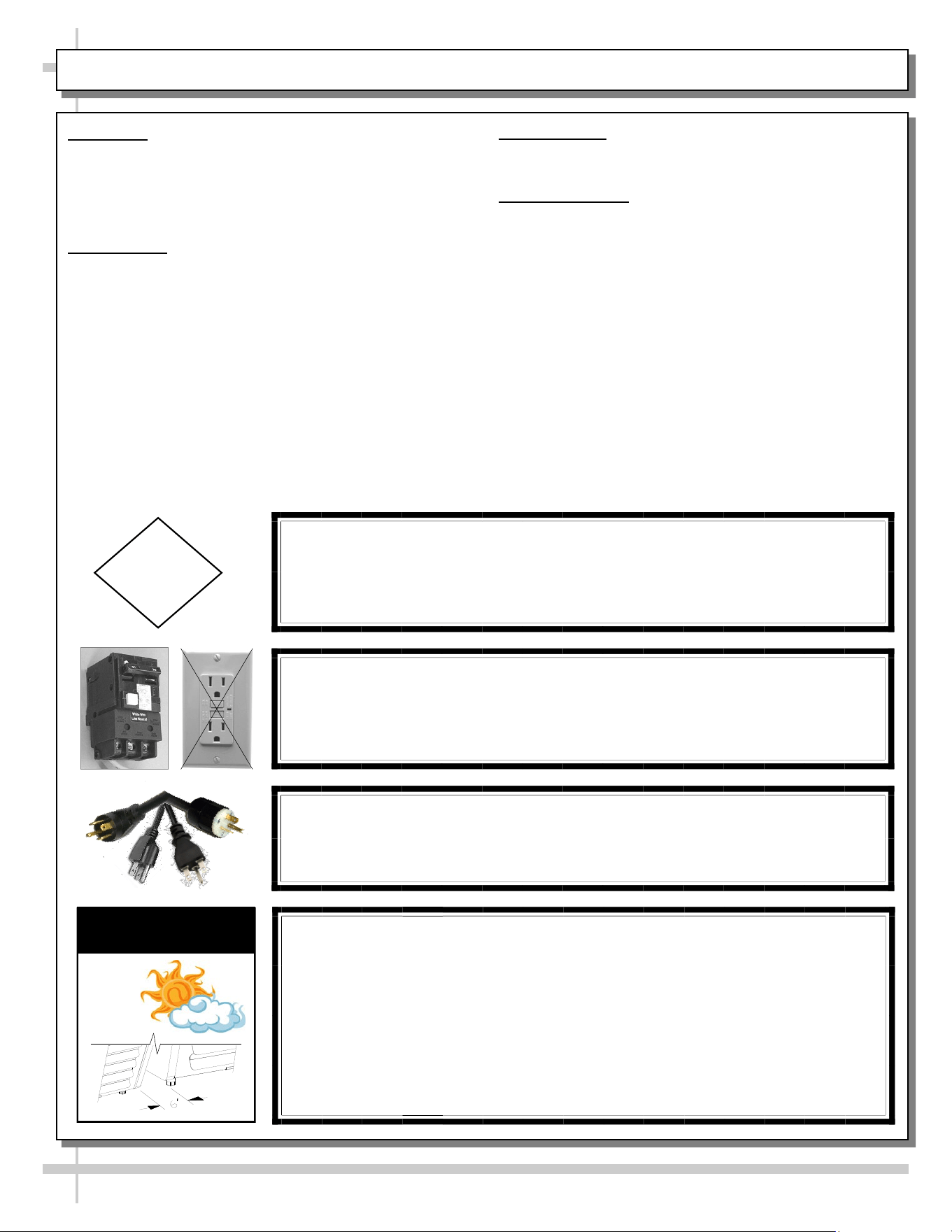
CAUTION! POWER CORD AND PLUG MAINTENANCE
Risk of electric shock. If cord or plug becomes damaged,
replace only with cord and plug of same type.
OVERVIEW / TYPE / COMPLIANCE / WARNINGS / PRECAUTIONS / WIRING / PLUGS - PAGE 2 of 2
CAUTION! GFCI BREAKER USE REQUIREMENT
If N.E.C. (National Electric Code) or your local code
requires GFCI (Ground Fault Circuit Interrupter) protection,
you MUST use a GFCI breaker in lieu of a GFCI receptacle.
OVERVIEW
• These Structural Concepts cases should be installed and
operated according to these instructions to ensure proper
performance. Improper use will void warranty.
• This unit is designed to display of products in ambient
store conditions with a max. temperature of 80 °F (27 °C) .
COMPLIANCE
• Performance issues when in violation of applicable NEC,
federal, state or local electrical codes are not covered by
warranty. See below.
PRECAUTIONS
• Following are important precautions to prevent damage
to unit or merchandise. Please read carefully!
WIRING DIAGRAM
• Each case has its own wiring diagram folded and in its
own packet. It may be placed near ballast box, field
wiring box, raceway cover, or other related location.
5
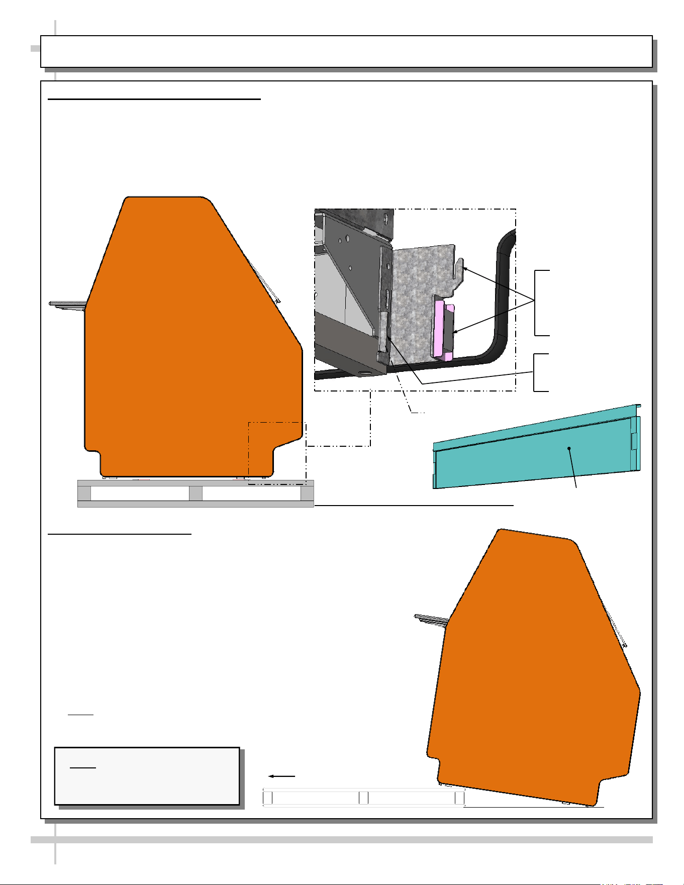
INSTALLATION: REMOVAL FROM PALLET / REMOVING & REPLACING TOE-KICKS
2. Remove From Pallet
• Remove shipping brace that may be securing case to
skid.
• Make sure front and rear toe-kicks are removed from
case before attempting to remove case from skid.
• Caution! Frame support rails can be damaged if case
hits floor with heavy force!
• Support case to prevent tipping.
• Carefully slide unit to rear of skid and tip backward off
skid.
• After case is in position attach front and rear toe-kicks.
• Illustration may not reflect every feature or option of
your particular case.
• Note: Blocking may be necessary to obtain adequate
height.
Slide Skid Out
Note: Illustration shown may
not reflect every feature or
option of your particular case.
J-Bar / Fork-Lift
Tab (Typ.)
Typical
J-Bar Lift
Hook And Magnet
For Front Panel
(No Screw Removal
Required)
1. Remove Toe-Kicks From Case
• Make sure front and rear toe-kicks are removed
from case before removing case from pallet.
• Caution! Frame support rails can be damaged if
case hits floor with heavy force!
• Front and/or rear toe-kicks consist of slots to
connect to hooks and connect to magnets.
• Panels may be lifted up and off case hooks (no
screw removal) and separated from magnets.
• Illustration below shows front panel after removal.
Front Panel (With Slot
For Hook (No Screw
Removal Required)
6
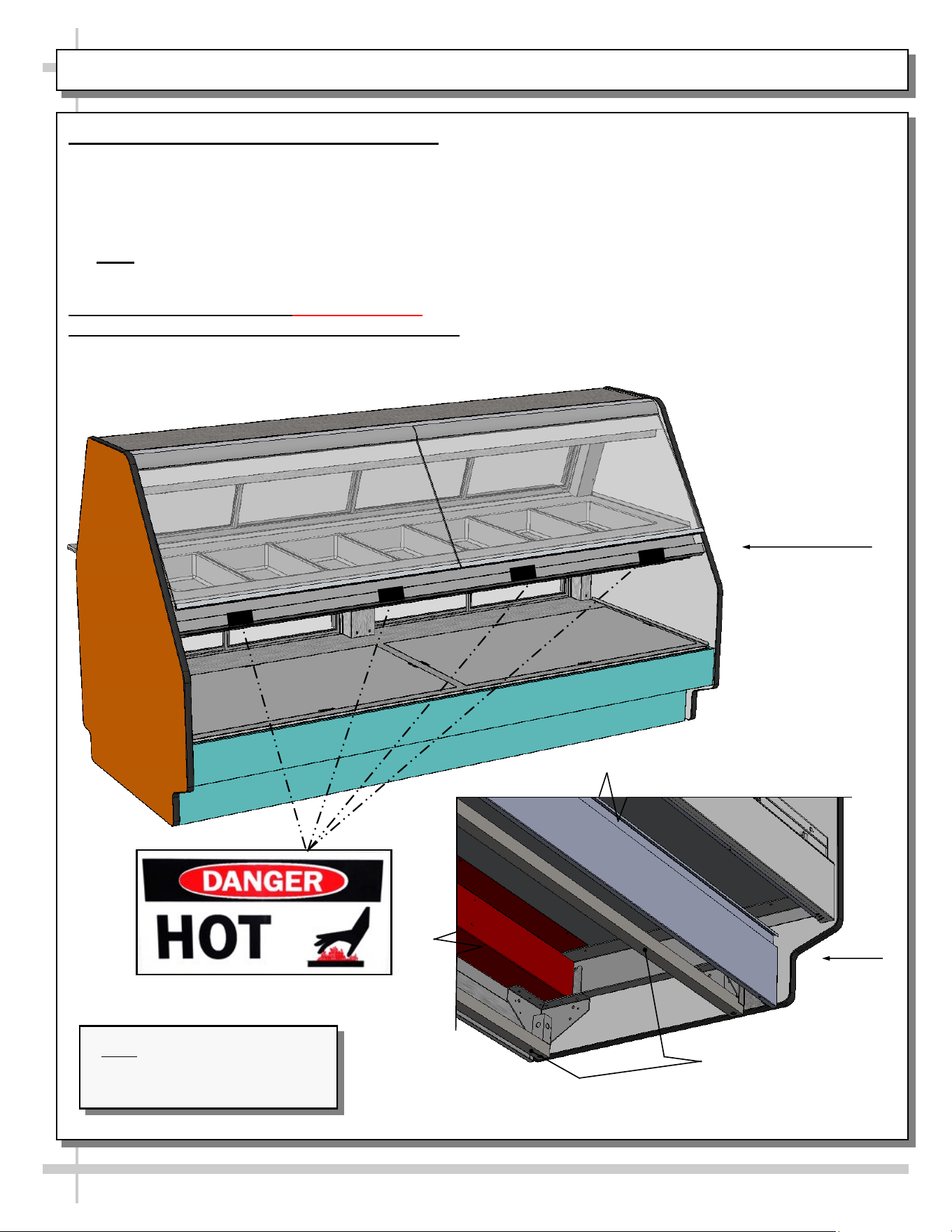
INSTALLATION, CONT’D: IMPORTANT! HEATED SHELF “DANGER - HOT” LABEL PLACEMENT
3. Frame Support Rails Must Be Shimmed
• Illustration below shows case with frame support
rails.
• Shims are provided with all cases that have frame
support rails.
• Use shims to level case.
• Note: After case is in position, seal to floor to
prevent entry or leakage of liquid or moisture.
4. Important! Check That “Danger - Hot”
(Or “Caution”) Labels Are Attached To Case
• Shelves can get extremely hot and cause severe
burns.
• Illustration below shows proper placement of
“Danger - Hot” Labels.
• Two labels must be placed on each shelf and
lower panel (as shown below).
• If labels are not properly attached, contact
Structural Concepts regarding label
P/N 20-11836.
• See SCC TECHNICAL SERVICE CONTACT
INFORMATION section in manual for contact
information.
Case
Front
Frame
Support Rails
Note: Illustration shown may
not reflect every feature or
option of your particular case.
Model
GCD856HHLB
Model
GCD656HHLB
7
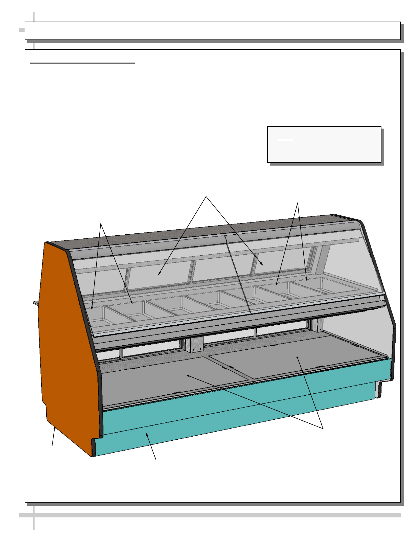
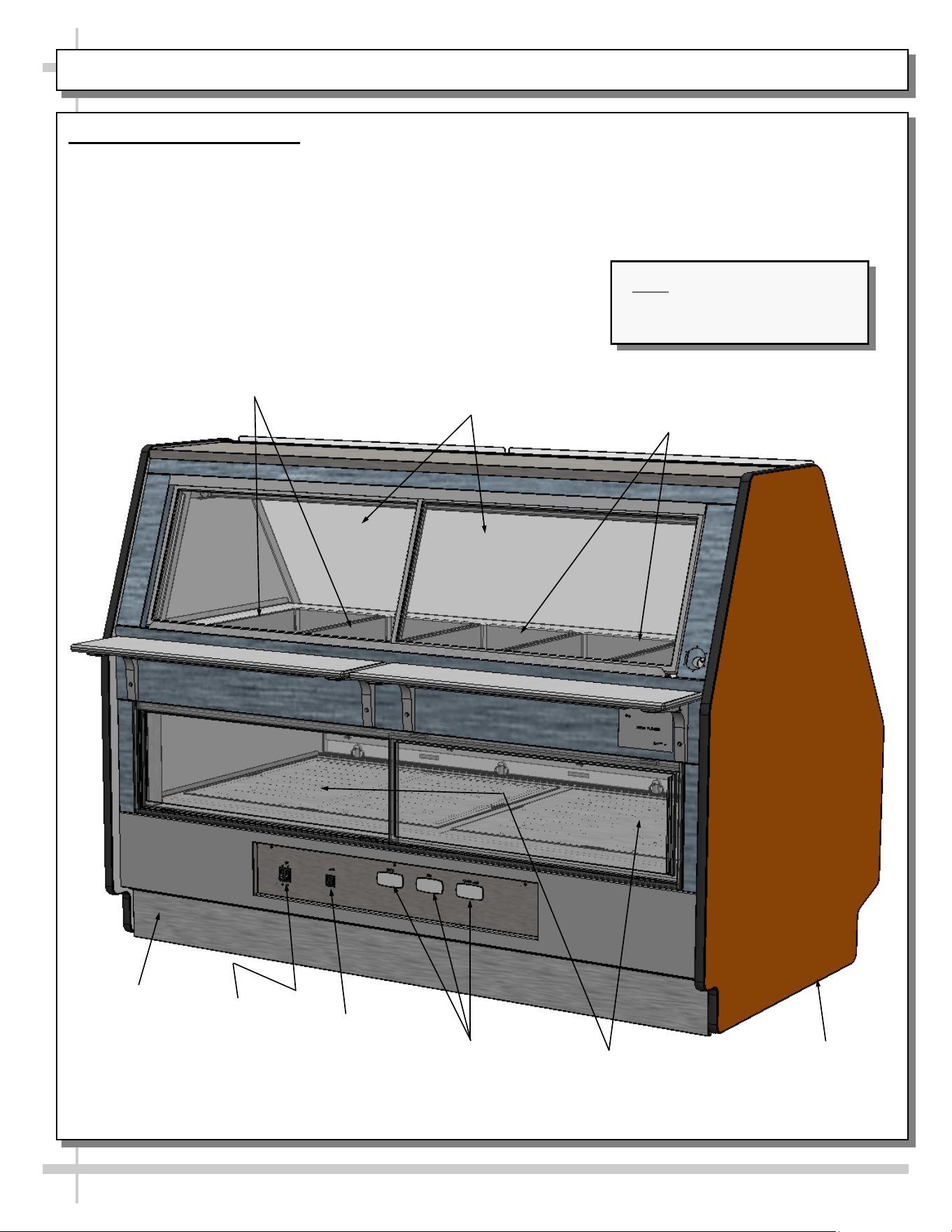
CASE OVERVIEW: HEATED PANS, FRONT GLASS, END PANEL, DECKS, TOE-KICK
1. Case Front Components
• Illustration shown may not reflect every feature or option of your particular case.
• See next page for case rear.
Decks
Toe-Kick
End Panel
Front Glass
Heated Pans (Typ.)
Heated Pans (Typ.)
Note: Illustration shown may
not reflect every feature or
option of your particular case.
Model
GCD856HHLB
8
CASE OVERVIEW, CONT’D: UPPER/LOWER SECTION REAR SLIDING DOORS, THERMOSTATS, ETC.
2. Case Rear Components
• Illustration shown may not reflect every feature or option of your particular case.
• See previous page for case front.
Toe-Kick
End Panel
Upper Section Rear
Sliding Doors (Typ.)
Heated Pans (Typ.)
Heated Pans (Typ.)
Lower Section Rear
Sliding Doors (Typ.)
Thermostats
Lights
Switch
Main Power
Throw Switch
Note: Illustration shown may
not reflect every feature or
option of your particular case.
Model
GCD656HHLB
9
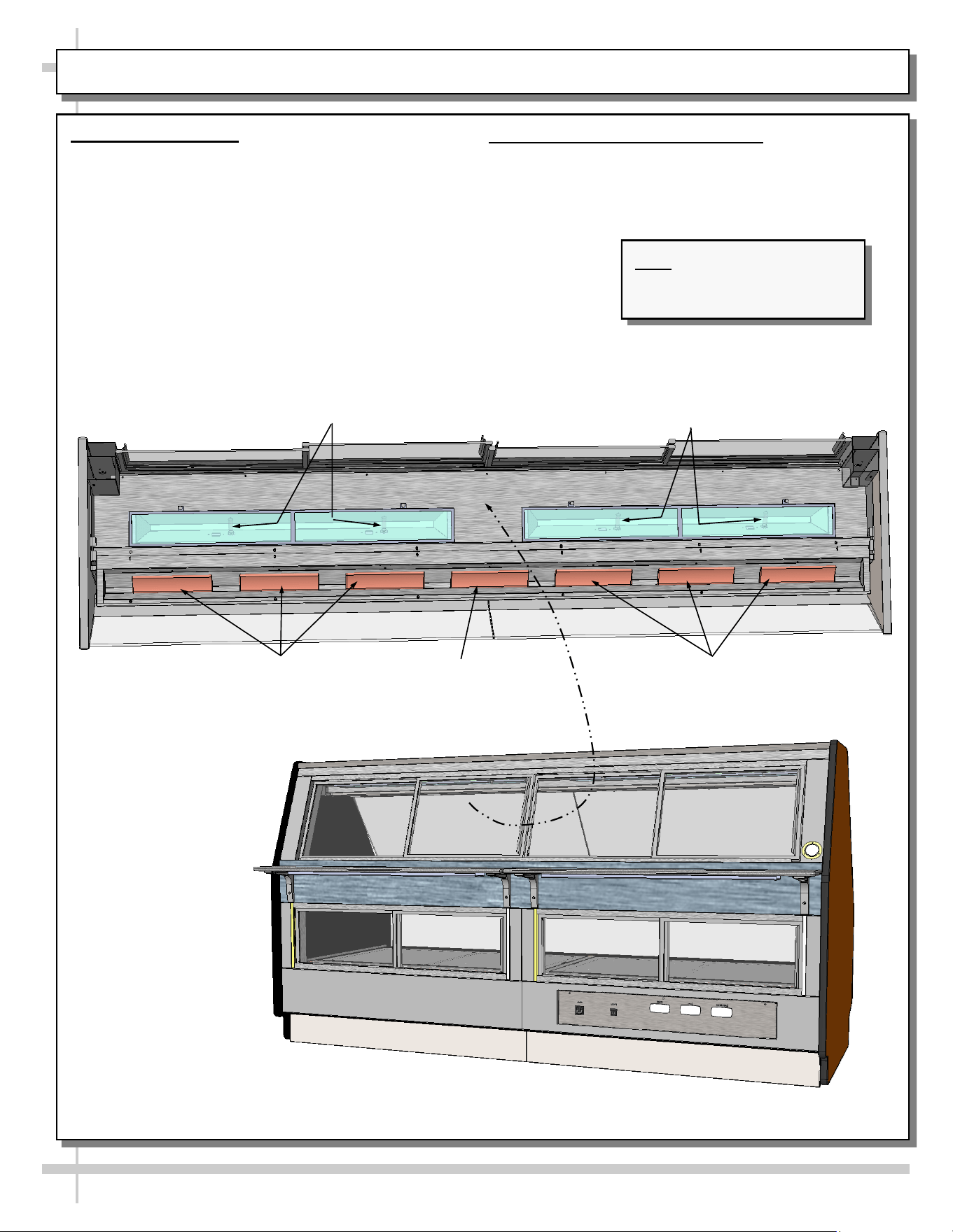
CASE OVERVIEW, CONT’D: CERAMIC HEATERS / CERAMIC METAL HALIDE LAMPS
Overhead
Ceramic Heater
Overhead
Ceramic Heaters
Overhead
Ceramic Heaters
3. Ceramic Heaters
• Red PREHEAT light will come on when MAIN
POWER SWITCH is turned on.
• Red PREHEAT light will turn off when
temperature has reached factory pre-set level.
Ceramic Metal Halide Lamps
4. Ceramic Metal Halide Lamps
• Ceramic metal halide lamps provide light to upper
service section of case.
Ceramic Metal Halide Lamps
--- Sectioned Upper View Shown Below ---
Note: Illustration shown may
not reflect every feature or
option of your particular case.
Model
GCD856HHLB
10
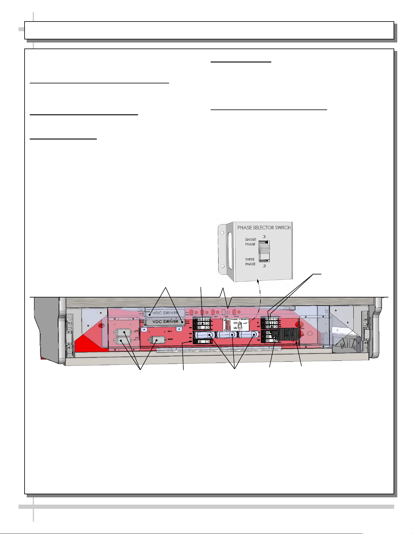
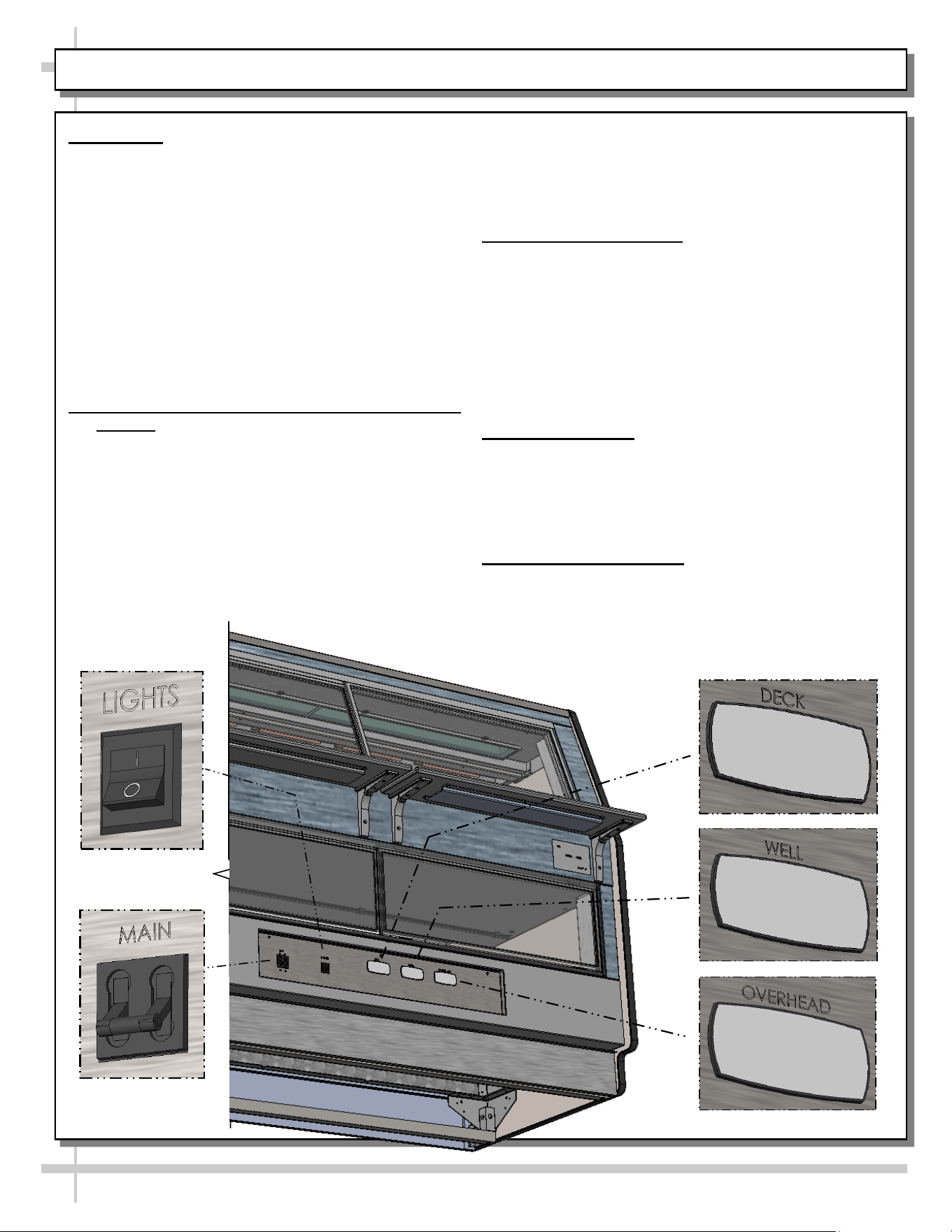
CASE OVERVIEW, CONT’D: FIELD ACCESS WIRING / SWITCHES / THERMOMETER / THERMOSTATS
Gain access to field wiring / electrical raceway by
removing rear panel (removal of screws is required).
5. Field Access Wiring Connections
Field wiring connection location is at rear-lower
section of case (as shown below).
6. MAIN Power Lever Switch
• See illustration below.
7. LIGHTS Switch
• See illustration below.
• Power to LED lights (lower section) and ceramic
metal halide lights (upper) are controlled by this
switch.
8. Thermometer
• Thermometer in equipment reflect internal air
temperature only (not actual food temperature).
• Use probe thermometers to determine actual
product temperatures.
9. Programmable Thermostats
• Separate upper and lower section thermostats are
provided.
Phase Selector
Switch
Terminal
Block
LED
Drivers
Lights
MAIN Power
Programmable
Thermostats
Relays
Terminal Blocks
--- Case Rear ---
Terminal
Block
11
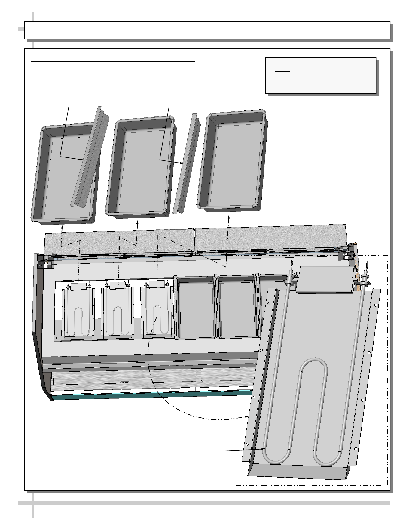
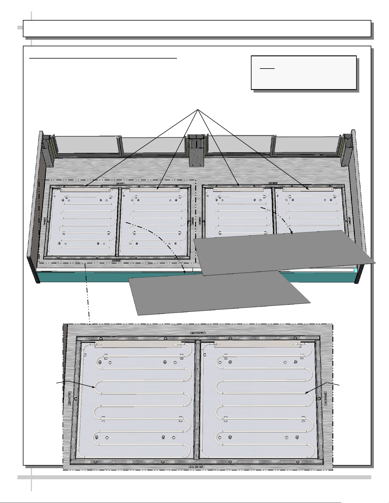
CASE OVERVIEW, CONT’D: HEATER ROD ASSEMBLIES (UPPER SECTION)
10. Heater Rod Assemblies (Upper Section)
• Heated wells are each controlled with individual heater rods.
• View below is sectioned for illustrative purposes only.
• See wiring diagram for more specifics.
Model GCD856HHLB
Shown Sectioned For Illustrative
Purposes Only
Heater
Rod (Typ.)
Divider
Divider
Pan Pan
Pan
Note: Illustration shown may
not reflect every feature or
option of your particular case.
12
CASE OVERVIEW, CONT’D: HEATER ROD ASSEMBLIES (LOWER DECK)
11. Heater Rod Assemblies (Lower Deck)
• Lower deck heat emanates via individual heater rods.
• View below is sectioned for illustrative purposes only.
• See wiring diagram for more specifics.
Model GCD856HHLB
Shown Sectioned For Illustrative Purposes Only
Heater
Rod
(Typ.)
Deck
Deck
Heater
Rod
(Typ.)
Note: Illustration shown may
not reflect every feature or
option of your particular case.
13
CASE OPERATION: MAIN POWER / LIGHTS / THERMOSTATS / OPERATING TIPS / SHUTDOWN
1. Start-Up - Note: This Section Is For
Authorized Personnel Only!
• Control panel is at case rear. It may be
accessed by removing rear panel (no screw
removal required).
• Main power switch, lights switch and thermostats
are on control panel. Replace front panel after
energizing control panel
• Turn main power switch on to energize case
(heated deck, heated shelves and lights).
• Turn on light switch for case lights to come on.
• Caution! Deck, shelving and overhead lights are
HOT! Do not touch until case has been turned off
and allowed to cool for 45 minutes!
2. Pre-Cooking Food / Checking Food Temp.
• Caution! Food MUST BE cooked PRIOR to
being placed in the case. Food should be heated
to between 150 °F to 160 °F (65.6 °C - 71 °C)
prior to placing it in the case.
• Temperatures of all food products are to be at
140 °F to 165 °F (60 °C to 74 °C), for shelves
and deck.
• Food temperature must NOT be allowed to be
below FDA guidelines of 140 °F (60 °C).
• Use ONLY food probe to check product
temperature before placing it in case.
DECK
• DO NOT rely on case thermometer or
infrared thermometer gun!
• After product is placed in case, check product
temperature (again) after one hour to verify that
proper food temperatures are maintained.
3. Thermostat Settings
• Important! Default thermostat settings are set
at the factory. This case should rarely require
adjustments to thermostat settings.
• If thermostat settings need to be adjusted, see
Programmable Controller section in user manual.
• If temperature is adjusted, allow 20 minutes at
NEW settings to determine if product
temperatures are acceptable.
• Check food temperature again after one hour.
4. Operating Tips
• When restocking, place new product at back and
rotate older product to front of case.
• Display product expected to sell within 4 hours.
• Clean up residue immediately. Spills will harden to
surface very quickly!
5. Shutting Down Case
• Remove all product from case.
• Turn main power switch to “OFF” position.
• Allow case to cool for 45 minutes before cleaning.
• See Cleaning Schedule section in User Manual
for specific cleaning instructions.
14
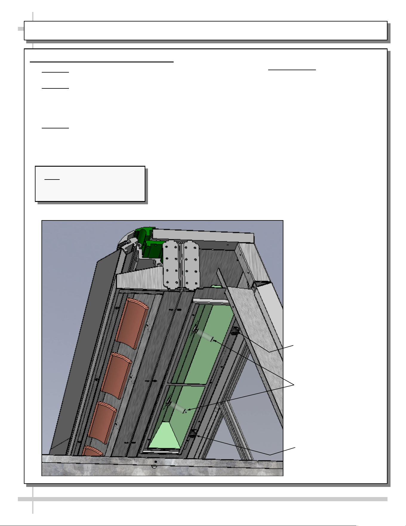
CASE OPERATION, CONT’D: CERAMIC METAL HALIDE LIGHT FIXTURES
6. Ceramic Metal Halide Light Fixtures
• Warning! Disconnect power before providing
maintenance & service to unit.
• Warning! Lamps are NOT manufactured to
resist breakage. Replace with same wattage
ceramic metal halide lamps (similarly
manufactured). If uncertain of wattage, refer to
label near rear sliding doors for specifics.
• Warning! As ceramic heaters may also heat up
light fixture area, make certain that entire area
has been allowed to cool before touching light
fixtures.
• As ceramic metal halide lamps may take up to 15
minutes to gain full illumination, turn on lamps
BEFORE loading product into case. This will
allow proper time for proper illumination.
• Find overhead light switch location on START-UP /
LIGHTING / CASE TEMP. / PRODUCT
HEATING / SCC TEMPERATURE
CONTROLLERS section in manual.
• Light switch turns on lamps to entire overhead
section of case.
• To access light fixtures, remove fasteners.
• Then, slide overhead lamp housing toward case
center (allowing screw to housing slot) and lower
housing down from case.
• Replace light fixtures as necessary.
Thumb Screw For
Lamp Access (Typical)
Ceramic Metal Halide
Lamps (Typical)
Thumb Screw For
Lamp Access (Typical)
Note: Illustration shown may
not reflect every feature or
option of your particular case.
15
Warning! Disconnect power before providing
maintenance and service to unit.
Caution: Lamps are treated to resist breakage
and must be replaced with similarly treated
lamps.
Note: Warranty will be void if claims arise from
negligence, misuse of goods, extreme
environmental conditions or improper
maintenance.
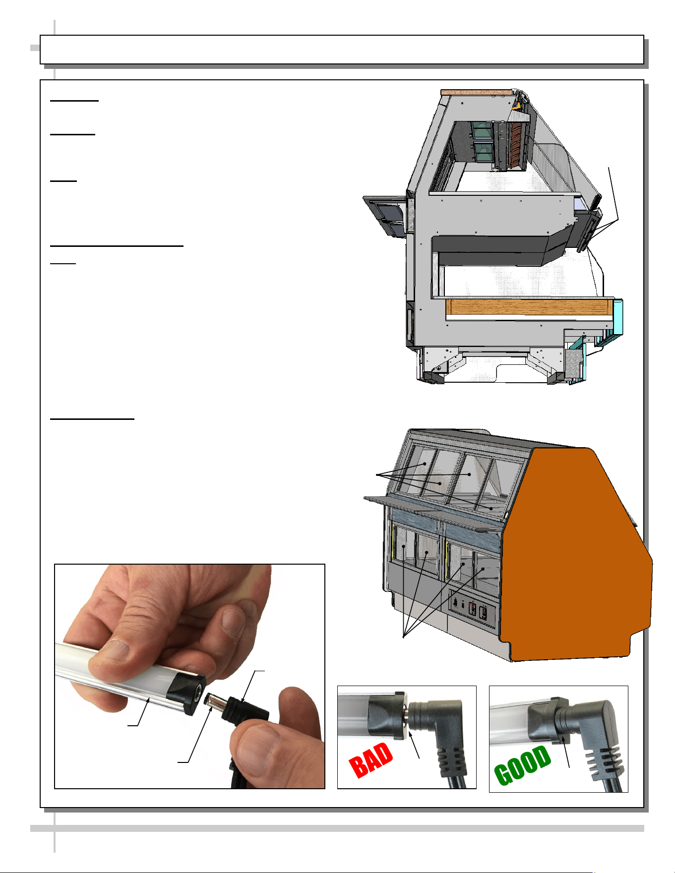
1. Rear Sliding Doors
Note: Doors are NOT interchangeable. There is an
inner and outer door. Outer door must be removed
first and replaced last.
• The outer door is the right hand door (from the
service side or rear of case).
• Move doors toward the center of the case.
• Individually lift each door up toward the top of the
case; pivot the bottom of the door out.
• Replace rear sliding doors in reverse order they
were removed.
2. LED Lights
• LED lights are located at both header
and shelving of case (as shown below).
• Check that ALL of the light plugs are
properly connected to the LED light.
• Plug must be inserted ALL THE WAY
into the LED light orifice (with no gap)
to work properly.
• See TROUBLESHOOTING section in manual
if LED lights malfunction.
MAINTENANCE: UPPER AND LOWER REAR SLIDING DOORS / LED LIGHT FIXTURES
LED Light
Fixtures
End Panel Removed
For Illustrative Purposes Only
Lower Rear
Sliding Doors
Upper Rear
Sliding Doors
No Gap
Gap
LED Light
Plug
LED’s Barrel
Shaped Insert
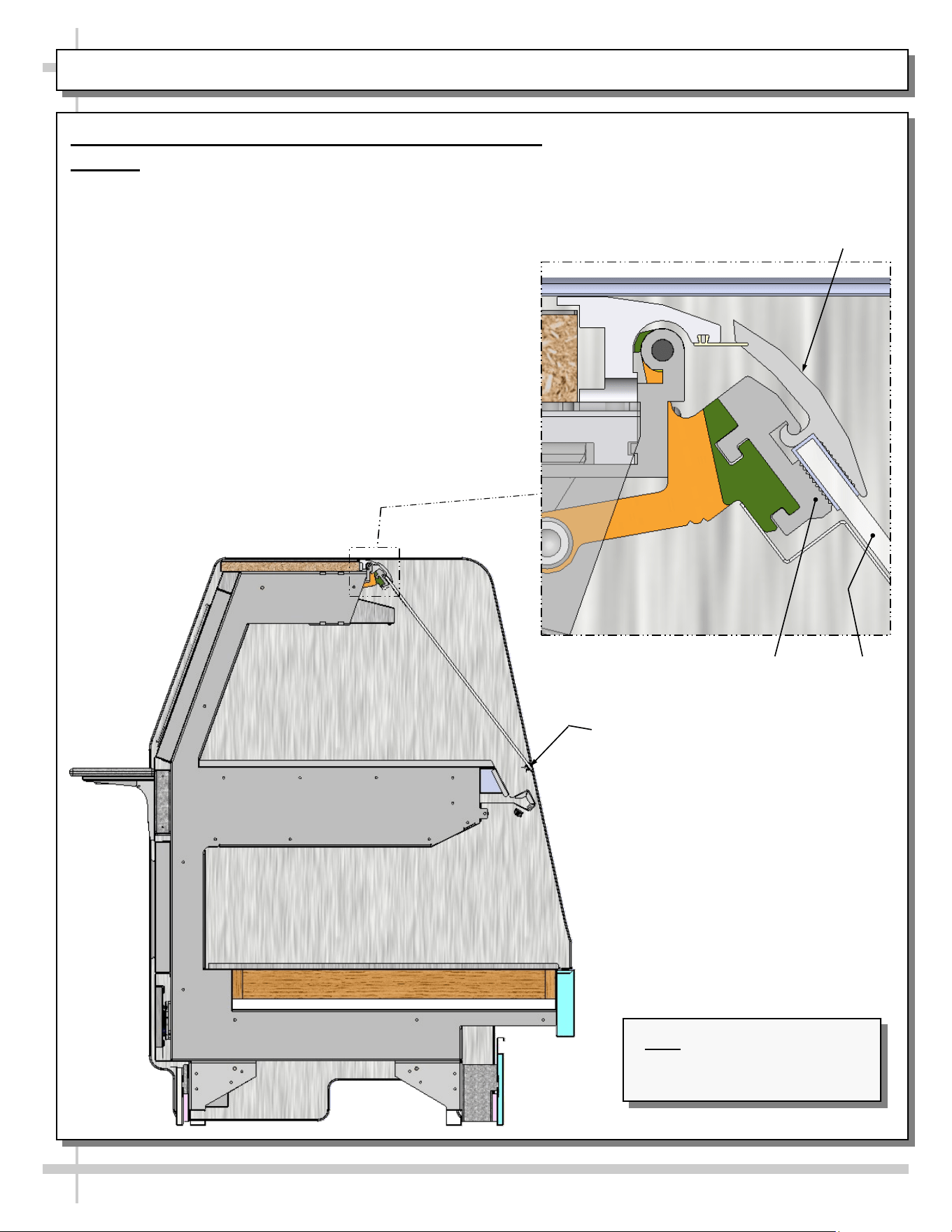
MAINTENANCE, CONT’D: FRONT GLASS ALIGNMENT & ADJUSTMENT / CLAMSHELL
16
3. Front Glass Alignment & Adjustment via Clamshell
Caution! Glass is extremely heavy! Two people may be
required to perform this task.
• Make certain case is level and plumb.
• To do so, lift glass to maximum upright position.
• Determine which side requires realignment.
• While maintaining tight grip on glass, loosen the
Allen™ screws nearest to misaligned side.
• Adjust the glass until properly positioned.
• Allen screws may now be tightened (taut, but not
overly tightened lest glass breakage occur).
• If other side needs alignment, repeat steps while
maintaining grip on glass.
Lift Handle
Clamshell
Upper
Clamshell
Lower
Glass
Note: Illustration shown may
not reflect every feature or
option of your particular case.
17
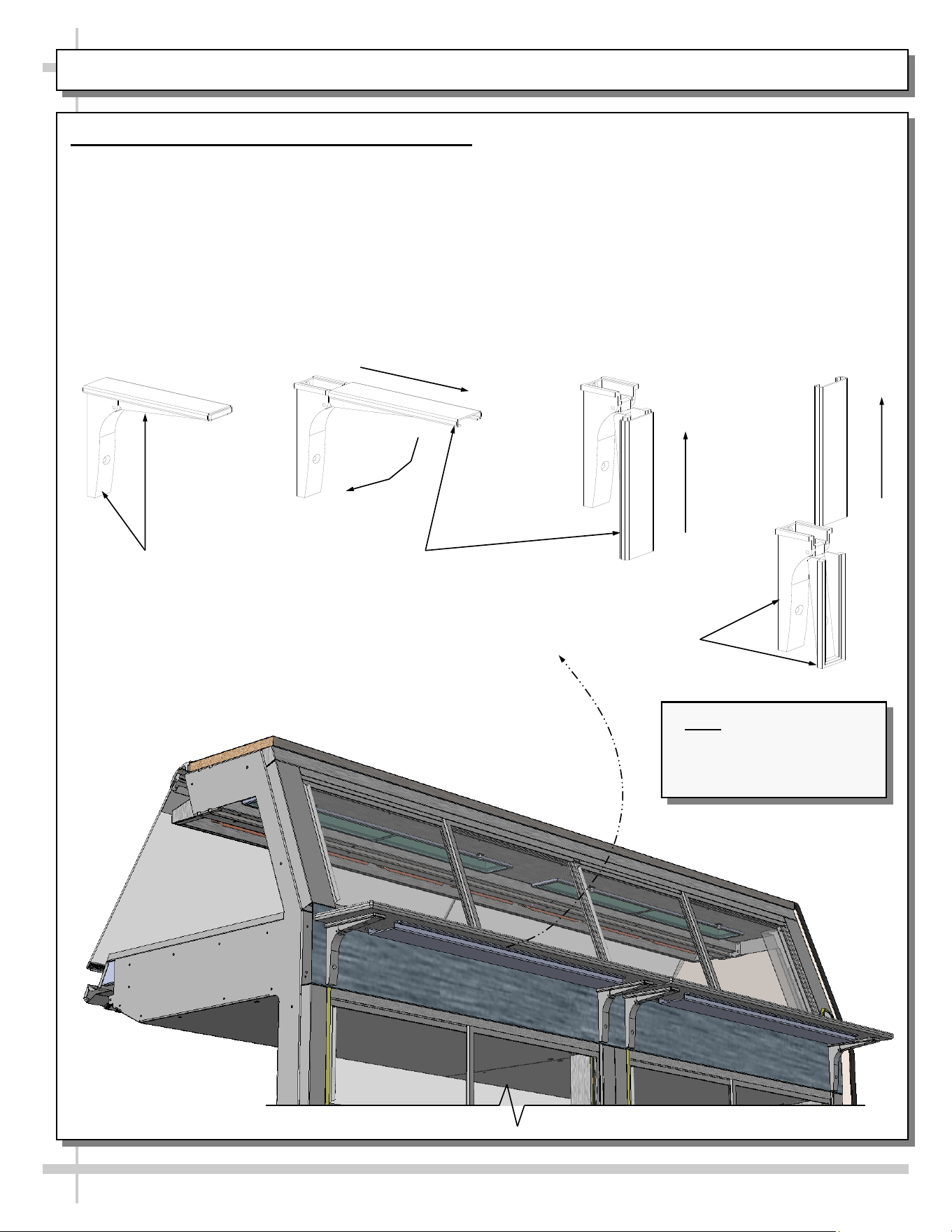
MAINTENANCE, CONTINUED: CUTTING BOARD/ REAR LEDGE REMOVAL
4. Cutting Board / Rear Ledge Removal Steps
Illustrations below reflect step-by-step removal
method.
A. Hinged support bracket is shown in its standard
upright position.
————— Rear Ledge Removal Steps —————
Note: For clarity, only Shelf Track is shown being
removed. Rear Ledge is attached to Shelf Track.
Hinged Support
Bracket
Shelf Track
- A - - B - - C -
- D -
Hinged Support
Bracket
B & C. While upright, rear ledge must be slid away
from case and then rotated downward to vertical
position.
C & D. From the shelf’s lowered position, lift from
bottom edge upward to disengage shelf track
(and attached rear ledge) from bracket.
Note: Illustration shown
may not reflect every
feature or option of your
particular case.
18
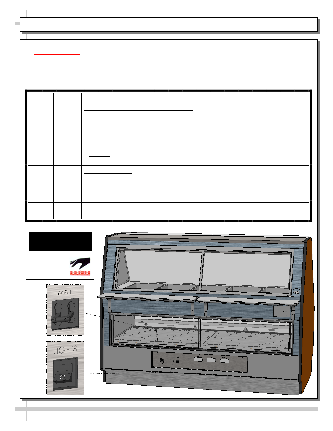
CLEANING SCHEDULE - TO BE PERFORMED BY STORE PERSONNEL - PAGE 1 OF 2
AREA FREQ. INSTRUCTIONS
Interior Daily Upper Heated Section Pans & Dividers: Remove pans (residing in heated wells)
and dividers. Warning! Do not access pans while unit is hot. Turn main power
switch (shown below). Allow wells to cool to room temperature before
cleaning.
• Pans: Remove, submerse in and wash with soap and water. If pans are Teflon®
coated, do not use wire “brillo” pads, or other abrasive pads that could scratch the
coating. Rinse dry.
• Dividers: Remove, submerse in and wash with soap and water.
• After cleaning, replace all items in reverse order they were removed.
Daily Upper Case Area: While upper pans are being cleaned, wipe down upper section
(around pan area) with hot water solution and anti-bacterial soap solution.
• Do NOT use wire Brillo® pads, or any coarse, abrasive brush or pads on top
surface.
• Rinse thoroughly. Dry with soft cloth.
Daily Lower Deck: Wipe off decks with moist cloth dipped in mild soap and water
solution.
Caution! TURN MAIN POWER SWITCH TO “OFF”
and allow case to cool at least 45 minutes before
cleaning upper case heated interior!
WARNING
HOT
SURFACE
19
CLEANING SCHEDULE - TO BE PERFORMED BY STORE PERSONNEL - PAGE 2 OF 2
AREA FREQ. INSTRUCTIONS
Exterior Daily Glass Surfaces: Clean all glass surfaces with household or commercial glass
cleaner. Clean out door track with moist cloth.
Daily Rear Sliding Door Exterior Glass (Upper and Lowe Exterior Glass: Clean with
household or commercial glass cleaner.
Daily End Panels, Front Panel, Toe-Kick, Rear Ledge Cutting Board, etc.: Wipe off
all surfaces with warm water and mild soap solution and non-abrasive cloth. Dry
thoroughly.
Daily Stainless Steel Surfaces:
• Wash with a solution of hand dishwashing liquid detergent and water; or a
solution of baking soda and water. Rinse and polish dry with paper towel or soft
cloth.
• Never use scouring powders or steel wool as they will scratch stainless steel.
• Brighten by polishing with a cloth dipped in vinegar or in ammonia; sprinkle baking
soda on sponge and rub gently; rinse. Polish dry with paper towel.
• Remove streaks or heat stains from stainless steel by rubbing with club soda.
Weekly Rear Sliding Doors (Upper and Lower): Remove from case and place in location
away from foot traffic; clean doors and door tracks with a household or commercial
cleaner. Return doors to case.
Weekly Wood, Laminate and Painted Surfaces (Including Rear Storage Area): Clean
with mild soap and water solution and a soft cloth .
Monthly Under Case Cleaning: Remove front or rear toe-kick. Vacuum under case to
remove all dust and dirt. Replace front toe-kick(s) when complete.
Caution! Front Glass must be raised and lowered very carefully. When closing, weight of
glass can pinch fingers between Front Glass and Case. Raise front curved glass.
Clean inside cavity at both ends of the hinged top cap with a mild soap and water solution.
20
CASE ISSUES TROUBLESHOOTING METHOD
Product temperature
deviates outside of
acceptable range.
Product either
overheating or too
cool.
• If a large amount of product was added to the case, it will take time for the
temperature to adjust. Product should be pre-heated before placing into
display case.
• Probe thermometer may be faulty. Use a stainless steel stem-type
thermometer with dial of at least a 1-inch internal diameter and test product.
Accuracy to within 1.8 °F / 1 °C is acceptable.
• Authorized Personnel Only: Adjust temperature control settings:
See CASE OPERATION... section in this manual for instructions.
System is not
operating at all
Check that unit is properly plugged in.
Confirm that the MAIN power “throw switch” is on.
If power cord is used, confirm that it is plugged into outlet.
Authorized Personnel Only:
• Confirm that the utility power is on.
• Check that case is properly hard wired.
Authorized Personnel Only:
Check the circuit breaker box for tripped circuits.
Authorized Personnel Only:
• GFCI may be required.
• If N.E.C. (National Electric Code) or your local code requires GFCI (Ground
Fault Circuit Interrupter) protection, you MUST use a GFCI breaker in lieu of
a GFCI receptacle.
Product is not heating
at all
Heating elements may be malfunctioning.
• Call Structural Concepts Technical Service (listed on last page of manual).
• Move product out of case until unit is repaired.
Ceramic metal halide
lights are not working
Caution! Case is extremely hot hot! Turn off main power switch and allow
case to cool for 45 minutes before touching light bulbs.
• Be sure ALL lights are screwed in properly.
• Check that bulbs are not burned out.
• Replace bulbs if they are burned out.
TROUBLESHOOTING - GENERAL ISSUES (PAGE 1 of 2)
21
TROUBLESHOOTING - GENERAL ISSUES (PAGE 2 of 2)
CASE ISSUES TROUBLESHOOTING METHOD
Case Lights Are Not
Working
Check that light switches are in the ON position.
• Check that ALL lights are plugged in and receptacles capped.
• See MAINTENANCE: UPPER AND LOWER REAR SLIDING DOORS /
LED LIGHT FIXTURES section in manual for illustrations showing good and
bad connections.
Clean dirt and dust from the bulbs to prevent flickering.
Check for burned out bulbs. Turn lights off & replace.
Authorized Personnel Only: Check to insure voltage at ballasts. If voltage
is entering but not exiting the ballast, ballast is faulty.
22
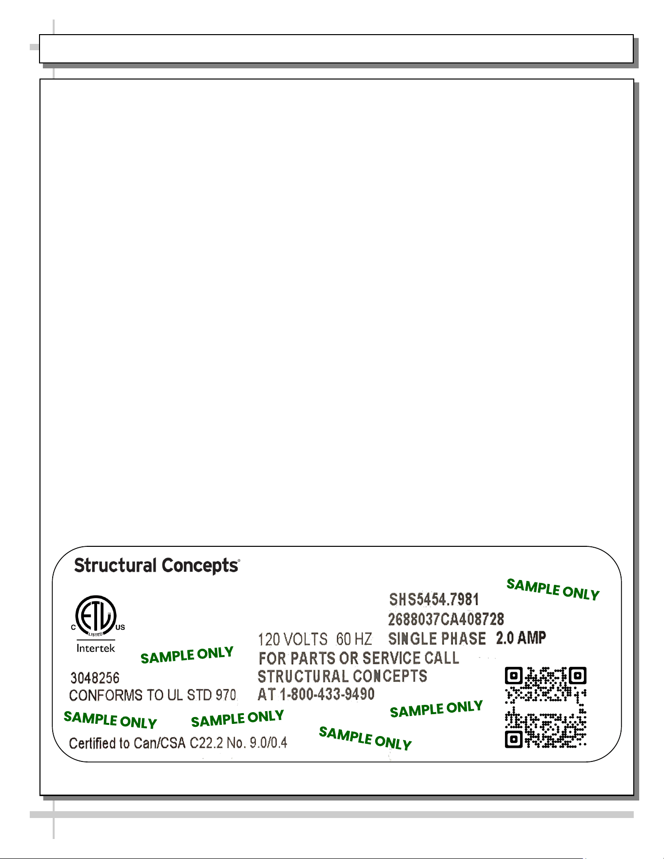
SERIAL LABEL LOCATION & INFO LISTED / TECH INFO & SERVICE / REFRIGERATED CASES ONLY
Serial Label Location & Information Listed /
Technical Information & Service
• Serial labels are affixed at a wide range of places
(on the header, near thermostat, at case rear,
behind panels/toe-kicks, on electrical boxes, etc.).
• Serial labels contain electrical, temperature and
refrigeration information, as well as regulatory
standards to which the case conforms.
• Sample serial label is shown. A variety of models is
displayed on serial label for illustration purposes only.
Your case’s serial label will reflect only one model.
• For additional technical information and service, see
the TECHNICAL SERVICE page in this manual for
instructions on contacting Structural Concepts’
Technical Service Department.
--- Sample Serial Label For Ambient/Heated Cases ---
888 E. Porter Rd - Muskegon, MI 49441
Sample QR Code
SCAN FOR PRODUCT LITERATURE
Reveal
Harmony
Impulse
Addenda
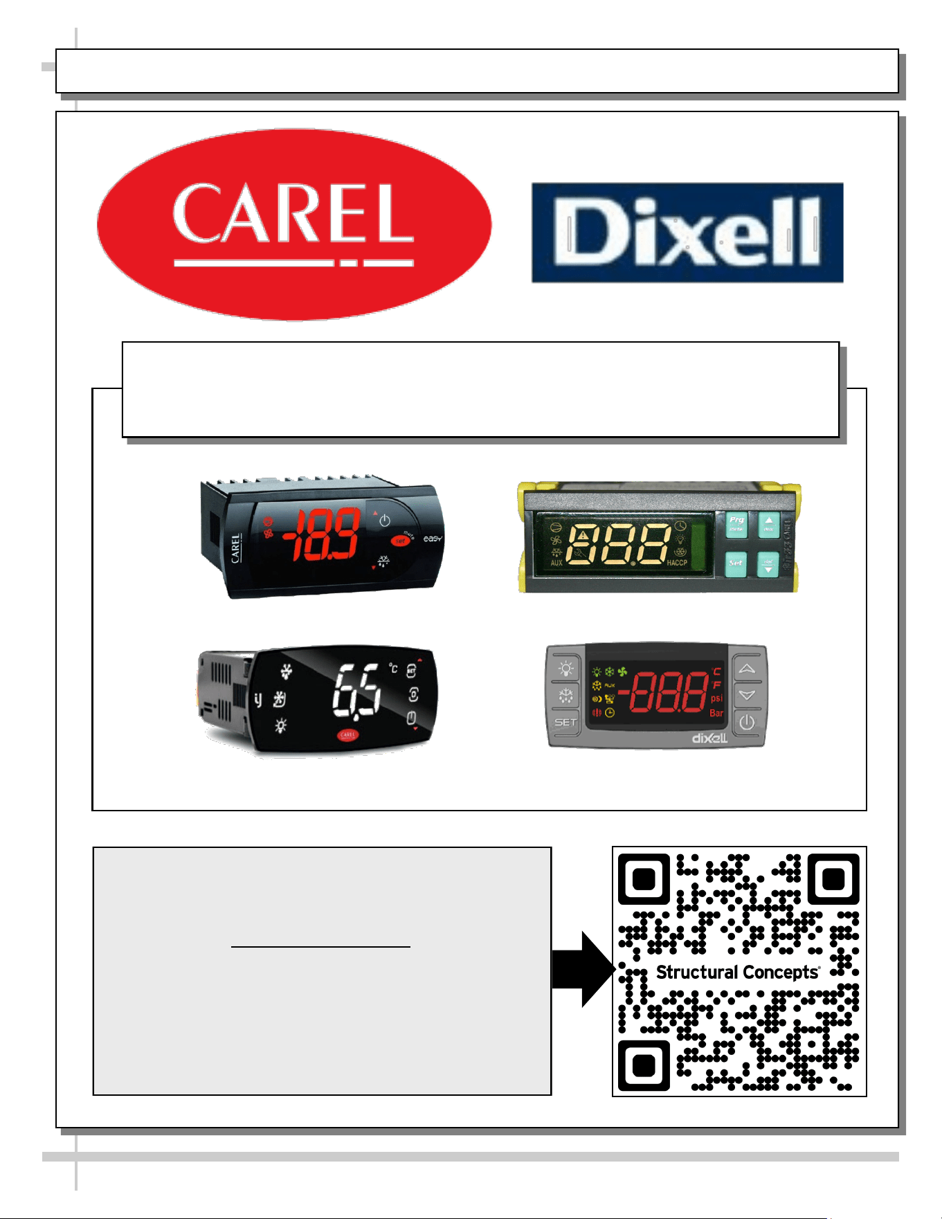
PROGRAMMABLE CONTROLLER (SELECT, CLICK ON OR SCAN QR CODE FOR INFORMATION)
23
Carel® iJF Platform
Carel® PJEZ Platform
Carel® ir33 Platform
Dixell® XM670K-XM679K Platform
To Access Information About The Programmable
Controller That Is Used On Your Case,
Follow These Instructions:
> If Viewing This Document on Smart Phone, Tablet
or Computer, Select/Click On The QR Code at Right.
> If Viewing This Document In Print (Hard Copy),
Scan The QR Code at Right With Your Smart Phone
or Tablet.
Determine Which Programmable Controller Is On Your Case (Controllers
That Are Commonly Used By Structural Concepts Are Shown Below).
Your Particular Programmable Controller May Differ.
24
STRUCTURAL CONCEPTS TECHNICAL SERVICE CONTACT INFORMATION & LIMITED WARRANTY
TECH SERVICE/WARRANTY CONTACT INFO:
1 (800) 433-9490 / EXTENSION 1
DAYS/HOURS AVAILABLE:
MONDAY - FRIDAY (CLOSED HOLIDAYS)
8:00 AM to 8:00 PM EST
YOU MUST HAVE THE FOLLOWING INFO AVAILABLE
BEFORE CONTACTING STRUCTURAL CONCEPTS:
SERIAL NO. / MODEL NO. / STORE NO. / STORE
ADDRESS / DETAILS (PHOTOS, LEAK LOCATIONS,
DAMAGE, STORE’S AMBIENT CONDITIONS, ETC.)
To Access The Limited Warranty To Your
Case, Follow These Instructions:
> If Viewing This Document on Smart Phone,
Tablet or Computer, Select/Click On The QR
Code at Right.
> If Viewing This Document In Print (Hard
Copy), Scan The QR Code at Right With Your
Smart Phone or Tablet.
