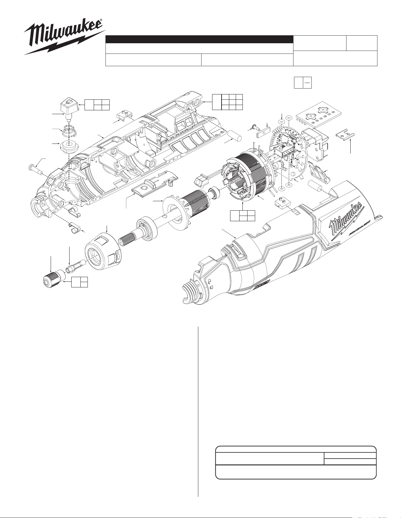
FIG. PART NO. DESCRIPTION OF PART NO. REQ.
1 --------------- Handle Support (1)
2 --------------- Handle Cover (1)
3 --------------- Light Pipe (2)
4 31-84-0040 Power Slider (1)
5 --------------- Spindle Lock Assembly (1)
6 --------------- Tower Spring (1)
7 --------------- Sleeve (1)
8 44-66-0216 Spring Plate (2)
9 31-89-0250 Switch Retainer (1)
10 06-82-7472 M2 x 6mm PH screw (1)
11 45-30-0038 Rubber Slug (2)
12 42-70-0058 Housing Connection Clip (1)
14 34-40-0089 O-Ring (4)
15 --------------- PCBA (1)
16 --------------- Stator (1)
21 42-76-0401 Nose Collar (1)
22 --------------- 1/8" Collet (1)
23 --------------- Collet Nut (1)
24 06-82-1087 M3 x 12mm PH Torx T-10 Screw (6)
25 --------------- Fuse (1)
26 12-20-0454 Service Nameplate (not shown) (1)
27 10-22-0319 Warning Label (not shown) (1)
28 10-22-0932 Fuel Gauge Label (not shown) (1)
30 14-46-0964 Spindle Lock Service Kit (1)
31 14-20-0788 PCBA/Stator Service Assembly (1)
32 14-50-0014 Rotor Service Assembly (1)
33 14-46-0963 Collet Service Kit (1)
34 14-38-0143 Housing Service Kit (1)
FIG. NOTES
26,27, A clean, dry surface is essential for proper performance for any
28 adhesive system. The area intended for application of any
adhesive label or nameplate must be prepared by cleaning with
isopropyl alcohol. The solvent is to be applied with a clean,
lint free applicator and the surface allowed to dry before applying
the label or nameplate.
EXAMPLE:
Component Parts (Small #)
Are Included When Ordering
The Assembly (Large #).
0
00
5
8
(2x)
14(4x)
11
(2x)
23
21
32
10
9
12
25
16
1
15
4
6
3
(2x)
2
7
24
(6x)
22
1 2 3
11 12 24
26 27 28
34
22
23
33
5 6
7
30
14 15
16
31
MILWAUKEE TOOL
l
www.milwaukeetool.com
13135 W. Lisbon Road, Brookeld, Wisc. 53005
Drwg. 2
FIG. PART NO. DESCRIPTION OF PART NO. REQ.
SCREW TORQUE SPECIFICATIONS
SEAT TORQUE
FIG. PART NO. WHERE USED (kgf-cm) (lb-in)
10 06-82-7472 Switch Retainer 2±1 2±1
24 06-82-0243 Handle 8±1 7±1
BULLETIN NO.
54-22-2465
SERVICE PARTS LIST
CATALOG NO. 2525-20
REVISED BULLETIN
SPECIFY CATALOG NO. AND SERIAL NO. WHEN ORDERING PARTS
M12
™
Brushless Rotary Tool
SERIAL NO.
DATE
Nov. 2023
WIRING INSTRUCTION
P06A
See Page 2
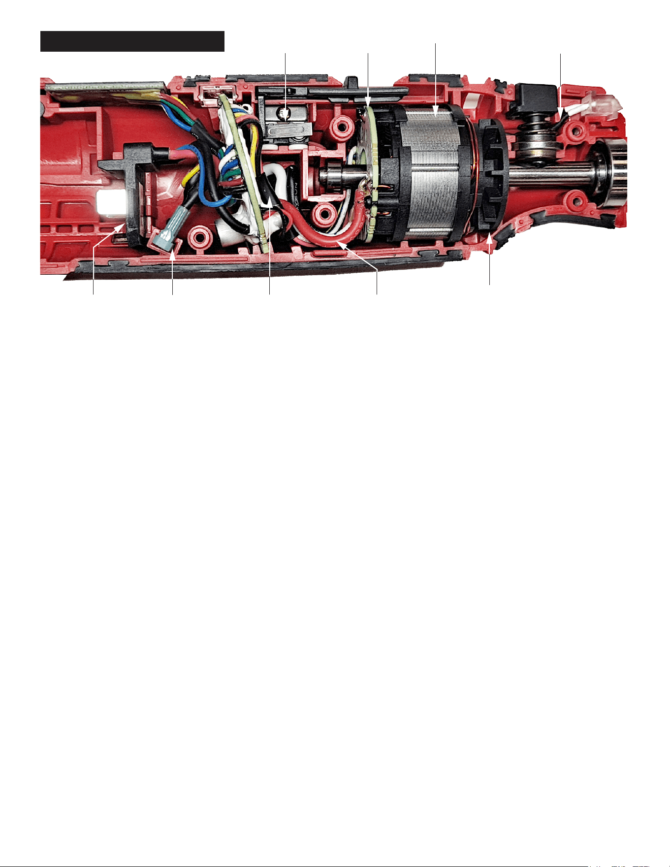
WIRE ROUTING
Keep the wiring
close to the PCB
FuseBattery
Terminal
Guide the wires
below the screw boss
Avoid interference between
LED wire and spindle lock button
Hall
Board
Trigger
Switch
Stator
Rotor
*Be sure all components
and wires are properly
seated before replacing
the housing cover with
screws.