

39j
39d
20
33c
33e
33a
33b
33d
33f
33j
34
35
36
29
25
23
22
21
31
27
24
38
39f
39a
26
37d
37h
39c(8x)
39b
39a 39b 39c 39d 39f
39g 39h 39j 39k 20
39
39h 20
39g
37a 37b 37c
37d 37h
37
33j
33h
33g
30
28 29
30 31
41
33a 33b 33c 33d 33e
33f 33g 33h 33j
33
37c
37a
37b
39k(2x)
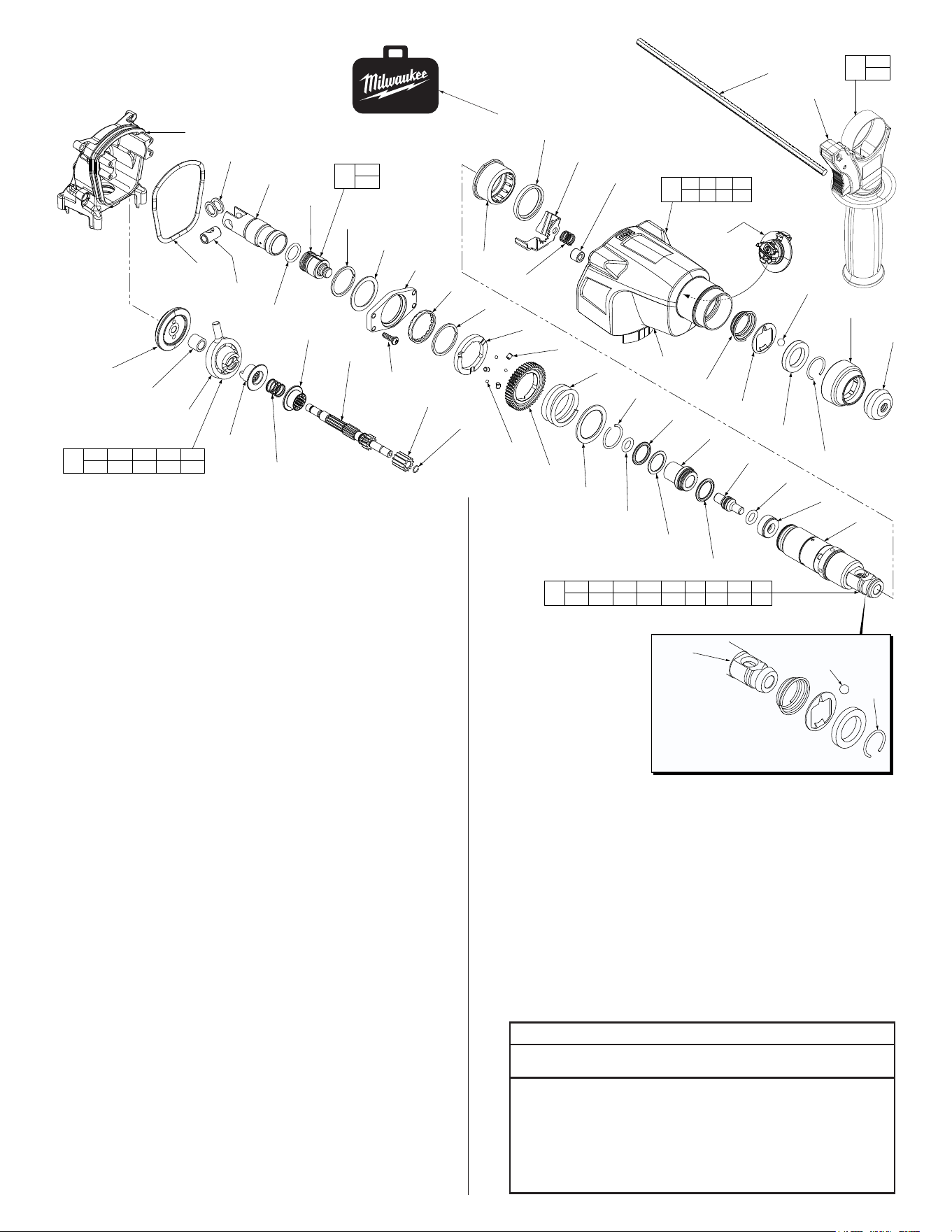
FIG. PART NO. DESCRIPTION OF PART NO. REQ.
20 05-78-0870 M4 x 0.7 x 24mm Taptite Screw (4 of 8) (4)
21 05-74-1020 M4 x .07 x 10mm Screw (1)
22 34-40-1570 O-Ring (1)
23 42-92-1625 Bearing Cover (1)
24 05-74-1030 M5 x 0.8 x 12mm Taptite Screw (2)
25 43-84-1050 Felt Block (1)
26 --------------- Gear Housing Cover (See Gearcase Assy.) (1)
27 05-74-1060 M4 x 1.79 x 22mm ST Screw (4)
29 31-15-3100 Crankcase (1)
30 34-40-1640 O-Ring (1)
31 02-04-5385 Ball Bearing (1)
33 44-66-1726 Bearing End Plate Assembly (1)
33a 32-60-1601 Pinion (1)
33b 02-04-2150 Ball Bearing (1)
33c 44-90-1060 C-Ring (1)
33d 45-06-1100 Lip Seal Ring (1)
33e 45-36-1800 Sleeve (1)
33f 44-66-1575 Bearing End Plate (1)
33g 05-78-0910 M4 x 0.7 x 12mm Taptite Screw (2)
33h 16-01-1200 Armature (1)
33j 02-04-5385 Ball Bearing (1)
34 42-96-0400 Bearing Cup (1)
35 18-01-2150 Field (1)
36 22-22-1800 Brush Holder Assembly (1)
37 23-66-0092 Electronics Assembly
Contains:On-OSwitch,PCBA,Terminal
BlockAssembly,RedLeadwireAssembly
and Black Leadwire Assembly (1)
37a 23-94-1971 Red Leadwire Assemby (1)
37b 23-94-1975 Black Leadwire Assemby (1)
37c 23-66-3000 On-OSwitch (1)
37d --------------- PCBA (1)
37h --------------- Terminal Block Assembly (1)
38 40-50-1090 Terminal Block Spring (1)
39 31-50-0042 Motor Housing Assembly (1)
39a 43-87-0150 Rubber Insulation Bellows (1)
39b 12-20-2605 Service Nameplate (1)
39c 05-81-5262 M4 x 1.4 x 18mm Plastite Screw (8)
39d --------------- Motor Housing Cover (1)
39f 45-24-1020 Forward/Reverse Shuttle (1)
39g --------------- Motor Housing Support (1)
39h 45-30-1980 4 x 15 Pin (2)
39j 45-30-1990 3 x 5 Pin (2)
39k 06-82-0032 M4 x 1.4 x 12mm Plastite Screw (2)
41 14-09-0100 Crankcase Assembly (1)
l
l
l
l
l
l
l
l
l
l
l
l
l
BULLETIN NO.
54-24-2652
SERVICE PARTS LIST
CATALOG NO. 2605-20
REVISED BULLETIN
SPECIFY CATALOG NO. AND SERIAL NO. WHEN ORDERING PARTS
M18™ 7/8" SDS Rotary Hammer
STARTING
SERIAL NO.
DATE
Aug. 2022
WIRING INSTRUCTION
D14C
EXAMPLE:
Component Parts (Small #) Are Included
When Ordering The Assembly (Large #).
0
00
SEE PAGE 4
54-24-2651
l= Components of the 14-46-2605
Rotary Hammer Service Kit
2 42-52-5262 Dust Cap (1)
3 42-76-5262 Locking Sleeve (1)
11-c 34-40-1410 O-Ring (1)
11-e 34-40-1425 O-Ring (1)
11-g 34-40-1440 O-Ring (1)
11-j 34-40-1450 O-Ring (1)
11-k 44-90-1025 C-Ring (1)
11-t 44-90-0215 C-Ring (1)
15 44-90-1030 C-Ring (1)
16-b 34-40-1510 O-Ring (1)
19 45-88-5200 Washer (2)
20 05-78-0870 Taptite Screw (8)
21 05-74-1020 M Screw (1)
22 34-40-1570 O-Ring (1)
24 05-74-1030 Taptite Screw (2)
25 43-84-1050 Felt Block (1)
27 05-74-1060 ST Screw (4)
28 43-44-1375 Gasket (1)
30 34-40-1640 O-Ring (1)
32-a 44-90-1180 C-Ring (1)
33-c 44-90-1060 C-Ring (1)
33-d 45-06-1100 Lip Seal Ring (1)
34 42-96-0400 Bearing Cup (1)
36 22-22-1800 Brush Holder Assy. (1)
39-c 05-81-5262 Plastite Screw (8)
39-k 06-82-0032 Plastite Screw (2)
49-08-5350 ‘P’ Grease
100g tube
(1)
49-08-5345 ‘Q2’ Grease
45g tube
(1)
l14-46-2605
Rotary Hammer Service Kit
= Part number change
from previous service
parts list.
37a
37b
Location of the Red Leadwire Assembly (37a)
and Black Leadwire Assembly (37b) on the
backoftheOn-O
Switch (37c)
MILWAUKEE TOOL
l
www.milwaukeetool.com
13135W.LISBONRD.,BROOKFIELD,WI53005
Drwg. 3
l
l
l
29
19
17
16a
15
14
13
12
11t
11s
11q
11n
11k
11h
11f
11d
11c
11b
11a
28
18
16b
32d
32c
20
32b
32a
11r
11p
11m
11j
11g
11e
32j
32h
32g
32f
32e
9d
9e
9a
8
7
5
4
2
3
6
10
9c
9f
9b
1b
1a
32a 32b 32c 32d 32e
32f 32g 32h 32j
32
11a 11b 11c 11d 11e 11f 11g 11h 11j
11k 11m 11n 11p 11q 11r 11s 11t
11
9a 9b 9c 9d
9e 9f 26
9
16a
16b
16
1a
1b
1
40
IMPORTANT NOTE:
When installing ‘C’ ring
#4 onto spindle #11a be
sure to position the “C’ ring
opening 180º from steel ball #6.
4
6
11a
FIG. PART NO. DESCRIPTION OF PART NO. REQ.
1 14-46-1450 Side Handle Assembly (1)
1a 14-34-0650 Auxiliary Side Handle (1)
1b 44-94-5381 Depth Rod (1)
2 42-52-5262 Dust Cap (1)
3 42-76-5262 Locking Sleeve (1)
4 44-90-5262 C-Ring (1)
5 44-90-5265 Ball Retaining Washer (1)
6 02-02-0275 7mm Steel Ball (1)
7 42-36-5262 Ball Support Plate (1)
8 40-50-5262 Conical Spring (1)
9 31-40-0600 Gearcase Assembly (1)
9a --------------- Gear Housing (1)
9b --------------- Needle Bearing (1)
9c --------------- Oil Shield (1)
9d --------------- Needle Bearing (1)
9e 40-50-0870 Spring (1)
9f 44-90-1010 Locking Plate (1)
10 44-10-5262 Shift Lever (1)
11 45-22-0850 Spindle Sleeve Assembly (1)
11a 38-50-0775 Spindle (1)
11b 45-88-2100 Stop Washer (1)
11c 34-40-1410 O-Ring (1)
11d 45-08-0650 Striker (Anvil) (1)
11e 34-40-1425 O-Ring (1)
11f 45-22-0870 Sleeve (1)
11g 34-40-1440 O-Ring (1)
11h 42-76-1000 Thrust Collar (1)
11j 34-40-1450 O-Ring (1)
11k 44-90-1025 C-Ring (1)
11m 45-88-2115 Washer (1)
11n 40-50-1720 Clutch Spring (1)
11p 32-75-1830 Spindle Gear (1)
11q 44-96-0300 Roller (3)
11r 02-02-1230 Steel Ball (3)
11s 42-70-0780 Clutch Disc (1)
11t 44-90-0215 C-Ring (1)
12 02-80-1750 Spindle Bearing (1)
13 42-36-2190 Bearing Bar Mounting Bracket (1)
14 45-88-5230 Washer (1)
15 44-90-1030 C-Ring (1)
16 44-82-5262 Striker and O-Ring Assembly (1)
16a 45-56-0300 Ram (1)
16b 34-40-1510 O-Ring (1)
17 44-62-5262 Piston (1)
18 44-60-5262 Wrist Pin (1)
19 45-88-5200 Washer (2)
FIG. PART NO. DESCRIPTION OF PART NO. REQ.
20 05-78-0870 M4 x 0.7 x 24mm Taptite Screw (4 of 8) (4)
28 43-44-1375 Gasket (1)
29 31-15-3100 Crankcase (1)
32 14-73-1601 Wobble Shaft Assembly (1)
32a 44-90-1180 C-Ring (1)
32b 32-60-1610 Pinion Gear (1)
32c 36-66-1620 Reduction Gear Shaft (1)
32d 32-60-1620 Internal Gear (1)
32e 40-50-2140 Spring (1)
32f 45-22-0925 Coupling Sleeve (1)
32g 36-92-0800 Wobble Plate (1)
32h 45-36-1825 Spacer (1)
32j 32-05-0626 Bevel Gear (1)
40 42-55-0050 Carrying Case (1)
l= Components of the 14-46-2605
Rotary Hammer Service Kit
l
l
l
l
l
l
l
l
l
l
l
SCREW TORQUE CHART
Seat Torque
Item Part Number Where Used (In./Lbs.)
20 05-78-0870 Mounting Bracket 43-52
20 05-78-0870 Motor Hsg. Cover & Support 21-26
21 05-74-1020 Crankcase Ball Bearing 20-24
24 05-74-1030 Bearing Cover 35-43
27 05-74-1060 Gear Housing Cover 13-18
33g 05-78-0910 Bearing End Plate 24-30
39c 05-81-5262 Motor Housing Cover 13-15
39k 06-82-0032 Motor Housing Cover 13-15
= Part number change
from previous service
parts list.
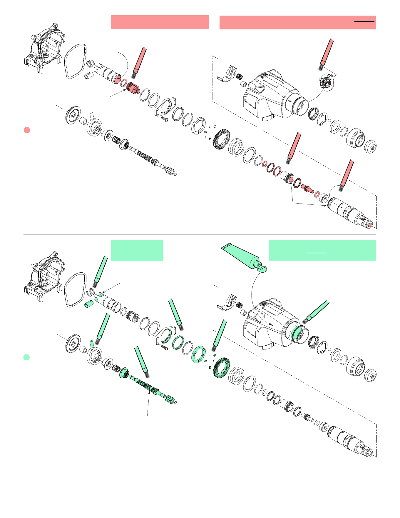
Prior to reinstalling,
clean gear assemblies
with a clean, dry cloth.
Lightly coat all parts highlighted here
with ‘P’ grease. Apply a greater amount
of grease to all internal and external gear teeth.
LUBRICATION NOTES:
Type ‘Q2’ Grease
No. 49-08-5345, 1.5 oz./45g tube
LUBRICATION NOTES:
Type ‘P’ Grease
No. 49-08-5350,
3.5 oz./100g tube
Place approx. 33 grams,
(1.2 oz.) of ‘P’ grease in the
gear cavity of the gearcase.
Place a very liberal
amount of grease to
the rear of the piston.
Apply a very light coat of grease to
the inside wall of piston. No grease
to inside base
of cavity.
Place a liberal amount of grease
along the whole length of the
reduction gear shaft.
Lightly coat all parts
highlighted here with ‘Q2’ grease
unless directed otherwise.
Coat the inside cavity
of the sleeve and spindle
with ‘Q2’ grease.
Coat the o-ring
on the shift lever
with grease.
No grease to the
face of ram
NOTE: The entire contents of the grease tube will not
be used. Use a total of appoximately 3/16 oz./5.4g.
NOTE: The entire contents of the
grease tube will not be used. Use a
total of appoximately 2 oz./59g.
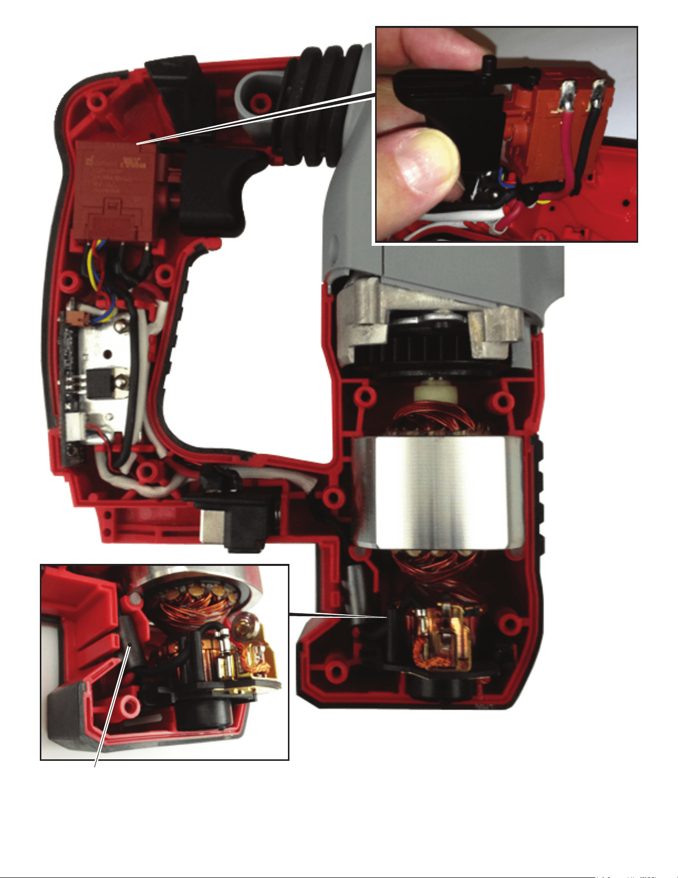
AS AN AID TO REASSEMBLY, TAKE NOTICE OF WIRE ROUTING AND
POSITION IN WIRE GUIDES AND TRAPS WHILE DISMANTLING TOOL.
BE SURE THAT ALL COMPONENTS OF THE ELECTRONICS KIT
ARE SEATED FIRMLY AND SQUARELY IN THE HANDLE RECESSES.
AVOID PINCHED WIRES, BE SURE THAT ALL WIRES AND SLEEVES
ARE PRESSED COMPLETELY DOWN IN WIRE GUIDES AND TRAPS.
PRIOR TO INSTALLING THE HANDLE COVER ONTO THE HANDLE
SUPPORT, BE SURE THAT THERE ARE NO INTERFERENCES.
Shown with ferrite bead
(Not used in 120V models)