
l
BULLETIN NO.
54-24-2791
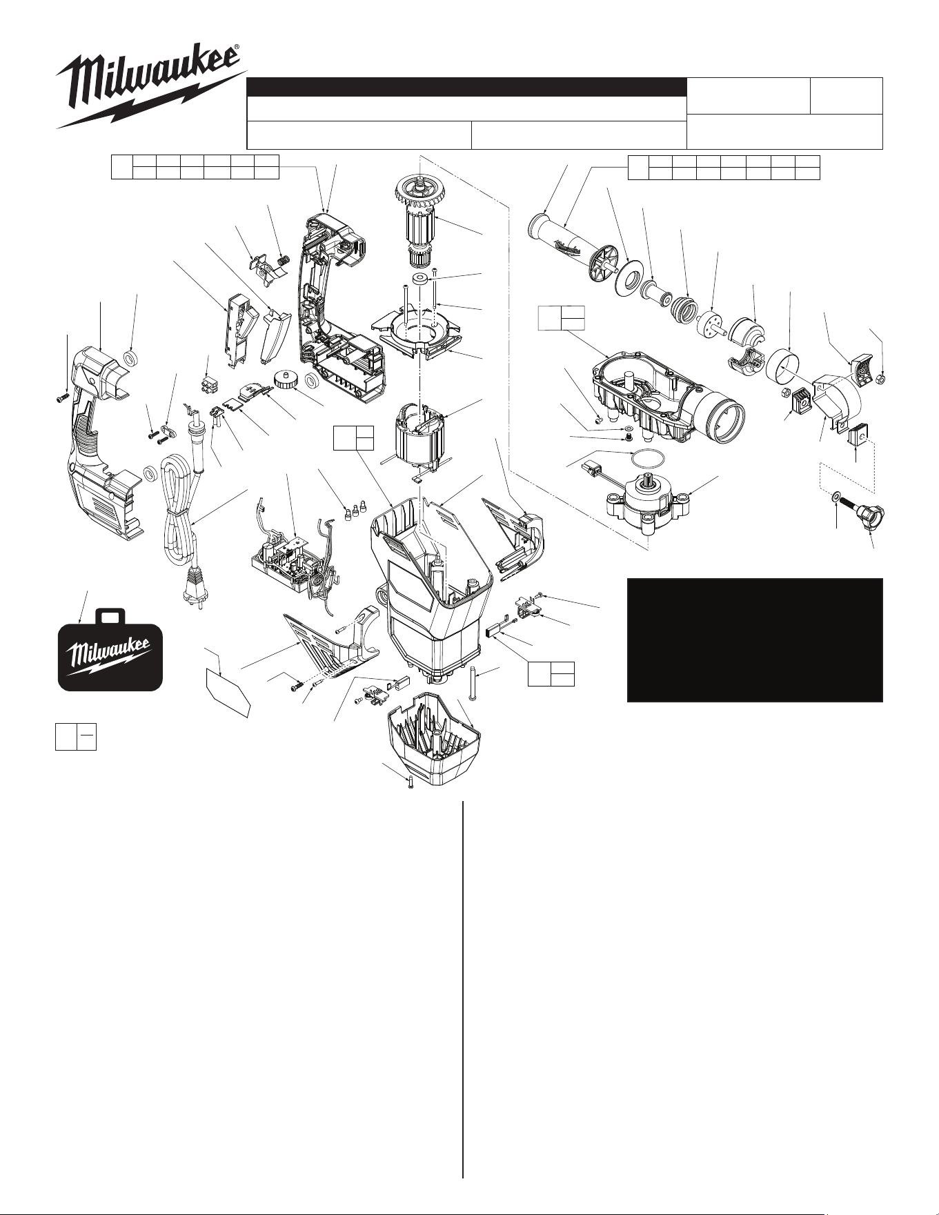
SERVICE PARTS LIST
CATALOG NO. 5546-21
REVISED BULLETIN
SPECIFY CATALOG NO. AND SERIAL NO. WHEN ORDERING PARTS
1-3/4" SDS-Max ROTARY HAMMER
DATE
June 2024
WIRING INSTRUCTION
K61B
EXAMPLE:
Component Parts (Small #)
Are Included When Ordering
The Assembly (Large #).
0
00
SEE PAGES 4 & 5
54-24-2790
l= Component of the
14-46-2719 Service
Maintenance Kit
• See page 2 for the exploded view and
parts listing of the mechanical portion
ofthetoolandservicextures.
• Seepage3forlubricationinstructions,
torqueschart,maintenanceinstructions
and service kits.
• SeePage4and5forwiringinstructions.
FIG. PART NO. DESCRIPTION OF PART NO. REQ.
21 42-62-0013 Side Handle Assembly (1)
21a 31-05-0011 Clamping Ring (1)
21b 05-89-0015 Fixing Screw (1)
21c 45-88-0103 Flat Washer (1)
21d 43-72-0002 Holder 1 (1)
21e 43-72-0003 Holder 2 (1)
21f 05-55-0018 Hex Nut (2)
21g 44-66-0049 Support Plate (1)
21h 44-90-0046 Ring (1)
21j 43-76-0012 Absorber Housing (2)
21k 44-52-0013 Absorber (1)
21m 43-87-0015 Bellows (1)
21n 43-24-0010 Extension (1)
21p 42-52-0031 Side Handle Cap (1)
21q 43-98-5316 Side Handle (1)
22 14-29-0039 Gearcase Assembly (1)
22e --------------- Flat Washer (1)
22f --------------- M6 x 10mm Pan Hd. Hex Drive Mach. Scr. (1)
42 06-82-8828 8-32UNC x .313” Pan Hd. Taptite T-20 Scr. (1)
43 34-40-0088 O-Ring (1)
44 42-70-0128 EM-Clutch Assembly (1)
45 05-88-1275 M4 x 70mm Pan Hd. ST Phillips Screw (2)
46 42-14-0027 FanBae (1)
47 16-01-0011 Armature Assembly (1)
48 02-04-0530 Ball Bearing (1)
49 18-01-0011 Field Assembly (1)
50 43-76-0013 Front Housing Support - Left (1)
51 43-76-0014 Front Housing Cover - Right (1)
52 06-82-2025 M3.5 x 16mm Pan Hd. Plastite T-10 Screw (2)
53 --------------- Motor Housing (1)
FIG. PART NO. DESCRIPTION OF PART NO. REQ.
54 05-88-0028 M6 x 55mm Pan Hd. Taptite T-30 Screw (4)
55 22-18-0011 120V Carbon Brush Assembly (1)
55a --------------- 120V Carbon Brush (1)
55b --------------- 120VCarbonBrushwithCut-O (1)
56 22-22-0021 Brush Holder Assembly (2)
57 05-78-5313 M4 x 9mm Pan Hd. Plastite T-15 Screw (2)
58 42-92-0049 Bottom Cover (1)
59 06-82-0121 M4 x 18mm Pan Hd. ST T-20 Screw (4)
60 14-20-0090 120V PCBA (1)
61 23-66-0059 120VOn-OSwitch (1)
62 45-72-0017 Switch Trigger (1)
63 14-34-0012 Handle Service Kit (1)
63a --------------- Handle Support - Left (1)
63b 42-42-0054 Foam Bushing (3)
63c --------------- Handle Cover - Right (1)
63d 44-66-0098 Auto Stop Plate (1)
63e 44-66-0099 LED Lens Holder Plate (1)
63f 44-06-0007 Working Lens with Ink Print (1)
63g 44-06-0008 Working Lens (1)
63h 05-78-5311 M5 x 18mm Pan Hd. ST T-20 Screw (7)
63j 40-50-0059 Spring (1)
63m 44-60-0074 Lock Button (1)
63n 43-98-0029 Speed Dial (1)
64 22-56-0475 Terminal Block (1)
65 31-17-0155 Cord Clamp (1)
66 06-82-0995 M4 x 16mm Pan Hd. Plastite T-20 Screw (2)
67 22-64-0019 120V Power Cord with Strain Relief (1)
68 22-56-0150 Closed End Connector (3)
73 12-20-0161 Service Nameplate (1)
74 14-38-0032 Motor Housing Kit (1)
75 42-55-0073 Blow Molded Carrying Case (1)
23-94-0048 Ground Wire Assembly (Not Shown) (1)
l
l
l
l
63h
(6x)
63c
63b
(3x)
61
62
63m
63j
63a
66
(2x)
65
64
63g
63f
63e
63d
63n
47
48
45
(2x)
46
49
50
53
67
60
68
(3x)
63h
52
(2x)
51
55a
55b
59
(4x)
54
(4x)
56
(2x)
57
(2x)
42
22e
22f
43
21f
(2x)
21g
21j
(2x)
21h
21k
21m
21n
21p
21q
21d
21a
21e
21b
21c
44
21a 21b 21c 21d 21e 21f 21g
21h 21j 21k 21m 21n 21p 21q
21
73
63a 63b 63c 63d 63e 63f
63g 63h 63j 63m 63n
63
55a
55b
55
53
73
74
22e
22f
22
58
75
MILWAUKEE TOOL
l
www.milwaukeetool.com
13135 W. LISBON RD., BROOKFIELD, WI 53005
Drwg. 4
SERIAL NO.
l
l
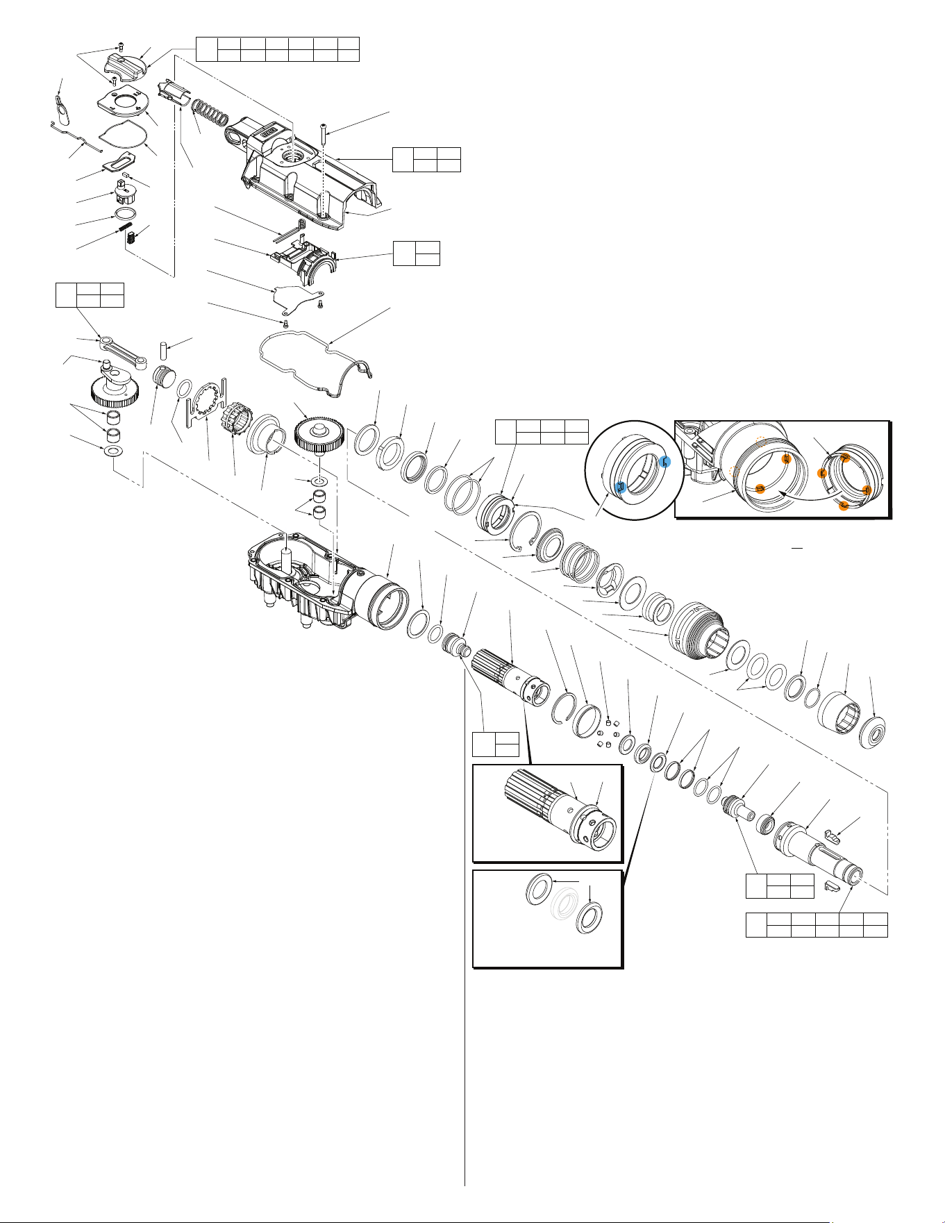
FIG. PART NO. DESCRIPTION OF PART NO. REQ.
23 02-50-0018 Needle Bearing (2)
24 45-88-0074 Washer (1)
25 32-10-0012 Clutch Assembly (1)
26 45-88-5327 Washer (1)
27 02-50-5315 Needle Bearing (2)
28 32-62-0010 Crank Shaft (1)
29 32-05-0016 Spindle Bevel Gear (1)
30 42-76-0014 Drive Sleeve (1)
31 44-66-0048 Locking Plate (1)
32 14-09-2820 Piston and Connecting Rod Assembly (1)
32a --------------- Wrist Pin (1)
32b --------------- Piston (1)
32c 44-94-0730 Connecting Rod (1)
33 43-44-0012 Rubber Gasket (1)
34 05-78-5313 M4 x 14mm Pan Hd. Taptite T-20 (2)
35 42-36-0024 Selector Bracket Clamp Plate (1)
36 14-46-0100 Fork Assembly (1)
36a --------------- Fork (1)
36b --------------- Fork Assembly Spring (1)
37 31-15-0137 Gearcase Cover Kit (1)
37a 31-15-0128 Gearcase Cover (1)
37b 40-50-0149 Spring (1)
37c 43-56-0011 Spring Carrier (1)
38 05-78-5315 M5 x 33mm Pan Hd. Taptite T-25 Screw (6)
39 23-66-0271 Selector Knob Assembly (1)
39a 31-53-0010 Rubber Plug (1)
FIG. PART NO. DESCRIPTION OF PART NO. REQ.
39b 40-50-5320 Spring (1)
39c 34-40-5309 O-Ring (1)
39d 44-60-0067 Selector Knob with Knob Pin Insert (1)
39e 44-20-0018 Chisel Lock Arm (1)
39f 43-44-0014 Selector Knob Gasket (1)
39g 43-56-0112 Selector Guide (1)
39h 06-82-0032 M4 x 12mm Pan Hd. ST T-20 Screw (2)
39j 43-98-0014 Selector Knob (1)
39k 31-53-0011 Felt Plug (1)
40 44-94-0014 Lock Rod (1)
41 42-50-0013 Lock Cam (1)
50-08-5317 Bit Grease (1)
FIG. PART NO. DESCRIPTION OF PART NO. REQ.
1 45-12-5316 Rubber Dust Shield (1)
2 45-22-5317 Front Latch Sleeve (1)
3 34-60-5316 Retaining Ring (1)
4 45-88-5316 Washer (1)
5 34-40-5316 Spindle O-Ring (2)
6 45-88-5321 Washer (1)
7 45-22-5319 Sliding Collar (1)
8 45-22-5321 Locking Sleeve (1)
9 45-88-5371 Washer (1)
10 44-66-0034 Front Spring Retainer (1)
11 40-50-5318 Spring (1)
12 44-66-5314 Rear Spring Retainer (1)
13 34-40-5315 Retaining Ring (1)
14 14-46-5316 Bearing Shield Assembly (1)
14a --------------- Bearing Shield (1)
14b 34-40-5321 O-Ring (2)
14c 45-06-5170 Felt Seal (1)
14d 45-06-5180 Rotary Seal (1)
14e 02-50-5316 Bearing Ring (1)
15 45-88-0076 O-Ring (1)
16 44-20-5316 Key (2)
17 38-50-0012 SDS-Max Spindle Assembly (1)
17a 44-82-5317 SDS-Max Spindle (1)
17b 44-90-0037 Brake Ring (1)
17c 44-90-0039 Rebound Ring (2)
17d 34-60-0072 Back Press Ring (1)
17e 44-60-5316 Spindle Sleeve Pin (6)
17f 44-90-5317 Steel Ring (1)
17g 44-90-5319 Spring Ring (1)
17h 45-22-0013 Barrel (1)
18 42-06-0028 Anvil Assembly (1)
18a --------------- Anvil (1)
18b 34-60-5319 O-Ring (2)
18c 45-06-5317 Turcon Seal (2)
19 45-56-0018 Striker Assembly (1)
19a 45-22-0016 Striker (1)
19b 34-40-0078 O-Ring (2)
20 45-88-0073 Washer (1)
22 14-29-0014 Gearcase Assembly (1)
l= Component of the 14-46-2719
Service Maintenance Kit
36a
36b
36
18a 18b
18c
18
7
1
2
3
4
5
6
15
14e
14d
14c
14b
14a
25
20
19b
19a
16
17a
17b
18a
18b
18c
17c
17d
17c
17e
17f
17g
17h
37b
37c
36b
36a
35
34
32a
38 (6x)
37a
33
17a 17b 17c 17d 17e
17f 17g 17h 18
17
19a
19b
19
29
30
31
19b
32b
32c
28
27
26
19b 32a
32b 32c
32
37a 37b
37c
37
39h
41
40
39e
39d
39c
39b
39j
39g
39f
39k
39a
39a 39b 39c 39d 39e 39f
39g 39h 39j 39k 40 41
39
22
24
23
17h 20
Washer
#20 is to be
located here on
barrel #17h
17c
Position
tapered side
of rebound rings
#17c to face striker #19
and anvil #18 as shown
14a 14b 14c
14d 14e
14
9
8
12
11
10
13
14a
24
14a (Back side)
Be sure to orient front notches of bearing shield
#14a at the 12:00/6:00 position or at the 9:00/3:00
position prior to installing in gearcase #22. Doing
so will allow tabs in rear of bearing shield to
seat in corresponding notches in gear
case cavity. This must be done to
allow for proper seating of
retaining ring #13.
l
l
l
l
l
l
l
l
l
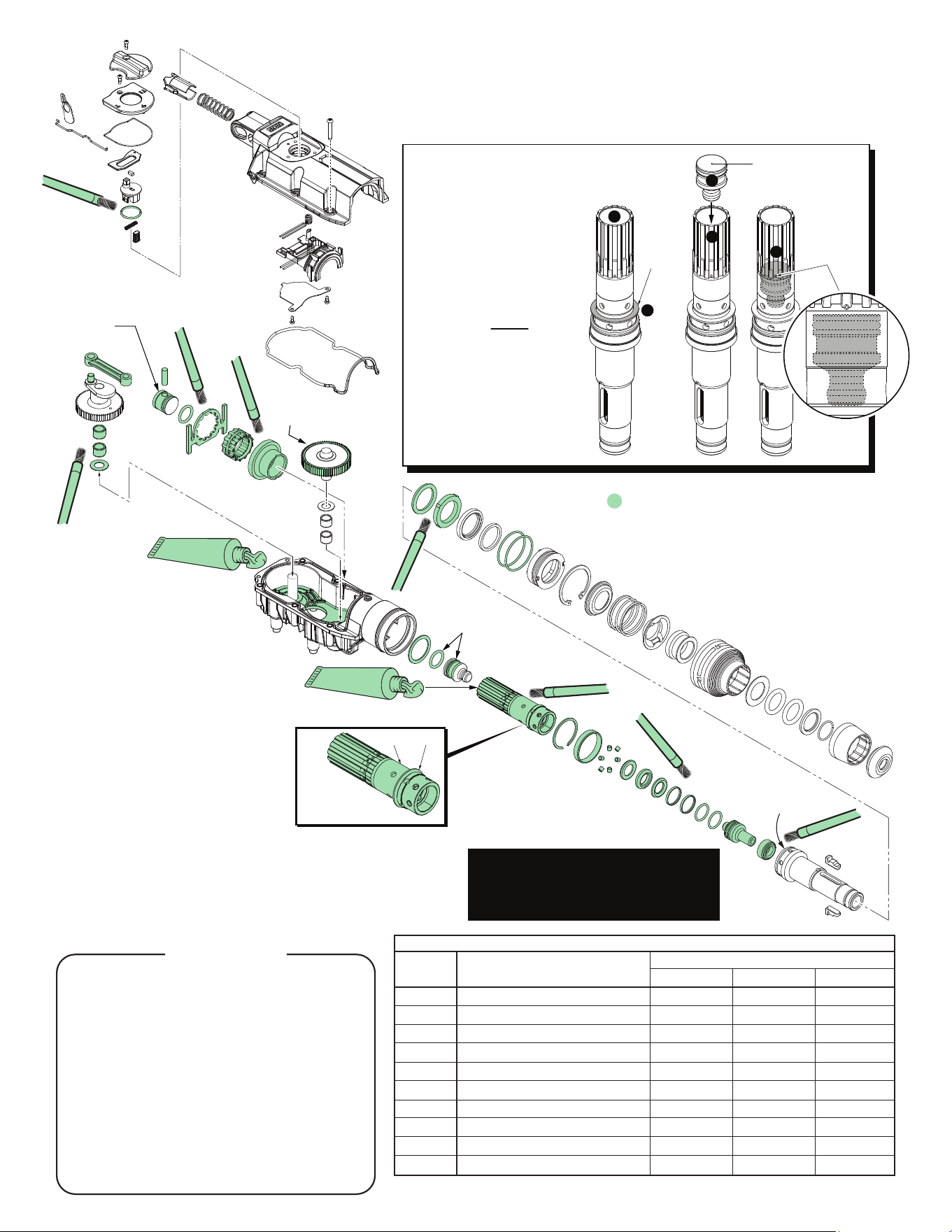
Pack the rear of the piston
with grease. There is to be
no lubrication on the face
of the part.
Place 6-5/16 oz. (180g)
of grease in the bottom
of the gearcase
Place 5/8 oz. (18g) of grease
in the rear of the barrel before
installing the striker
Coat the inside
of the spindle driver
prior to assembly
Coat teeth of
clutch assembly
with grease
Coat o-ring and
o-ring groove prior
to installing o-ring.
With o-ring
installed, coat around
entire side of ram
17h 20
Washer
#20 is to be
located here on
barrel #17h
Fig. 1
Small
hole in
barrel
1. Place washer #20 onto backside of barrel.
2. Place 18 grams of ‘Q2’ grease inside barrel.
3. Coat o-ring groove on ram
and o-ring with grease prior
to installing o-ring on ram.
Coat the assembled ram and
o-ring with grease as shown
below.
4. When placing ram assembly
into barrel, slowly apply
pressure to ram assembly.
5. Push the ram assembly until
rear face is just below small
hole in the barrel. DO NOT
wipe off any excess grease
that oozes out of holes.
No grease on rear
face of ram (striker)
#19a
Washer
#20
2
5
5
1
4
3
LUBRICATION NOTES:
Type ‘Q2’ Grease, No. 49-08-5355
(2.8oz, 80g tube) 3 tubes needed
Prior to reinstalling, clean gear assemblies with
a clean, dry cloth. Lightly coat all individual
parts highlighted here with grease. Apply a
greater amount of grease to all internal and
external gear teeth. Place 18 grams
of grease in the rear of the barrel
prior to inserting the ram. Place the
remaining grease in the
bottom of the gearcase.
Lubrication Note: MILWAUKEE recommends that scheduled maintenance of this Rotary
Hammer include lubrication replacement, and replacement of vital O-rings and gaskets at each
carbon brush change. Doing so will prolong the life of the hammer by reducing wear to gears
and mechanism parts. The carbon brushes and armature commutator in this MILWAUKEE
Rotary Hammer are designed and matched for many hours of reliable performance.
l
14-46-2719 MAINTENANCE SERVICE KIT
THIS KIT CONTAINS:
1 45-12-5316 Rubber Dust Shield
1 34-60-5316 Retaining Ring
2 34-40-5316 Spindle O-Ring
2 34-60-5319 O-Ring
2 45-06-5317 Turcon Seal
2 34-40-5308 O-Ring
2 42-42-0054 Foam Bushing
1 14-46-5316 Bearing Shield Assembly
1 34-60-0072 Back Press Ring
2 34-60-0078 O-Ring
1 43-44-0012 Rubber Gasket
1 34-40-5309 O-Ring
1 44-90-5319 Spring Ring
3 49-08-5355 ‘Q2’ Grease (2.8oz/80g tube)
1 22-18-0011 120V Carbon Brush Assembly
FASTENER TORQUE SPECIFICATIONS
SEATING TORQUE
FIG.NO. WHEREUSED lb-in kgf-cm Nm
34 Selector Bracket Clamp Plate 11 13 1.3
38 Gearcase Cover 44±3 51±4 5.0
47 Motor Housing 56 65 6.4
48d Housing Halve Cover 25 29 2.9
48c Housing Halve Cover 11 13 1.3
50b Coin Cell Cover 2.6 3.05 0.3
39h Selector Knob 16 18 1.8
39h On-OSwitch 11 13 1.3
Switch Termination Screws 8 10 1.0
Ground Screw-Gearcase 44 50 5.0
NOTE:
Besurethattheshankofthebitisclean.
Forbestperformance,besuretheshank
is lightly greased prior to installation.
Use Bit Grease No. 50-08-5317.
1
2
2
3
10
9
8 7
6
4
11
12
13
10
9
9
8
8
8
3a
3b
3a
3b
13
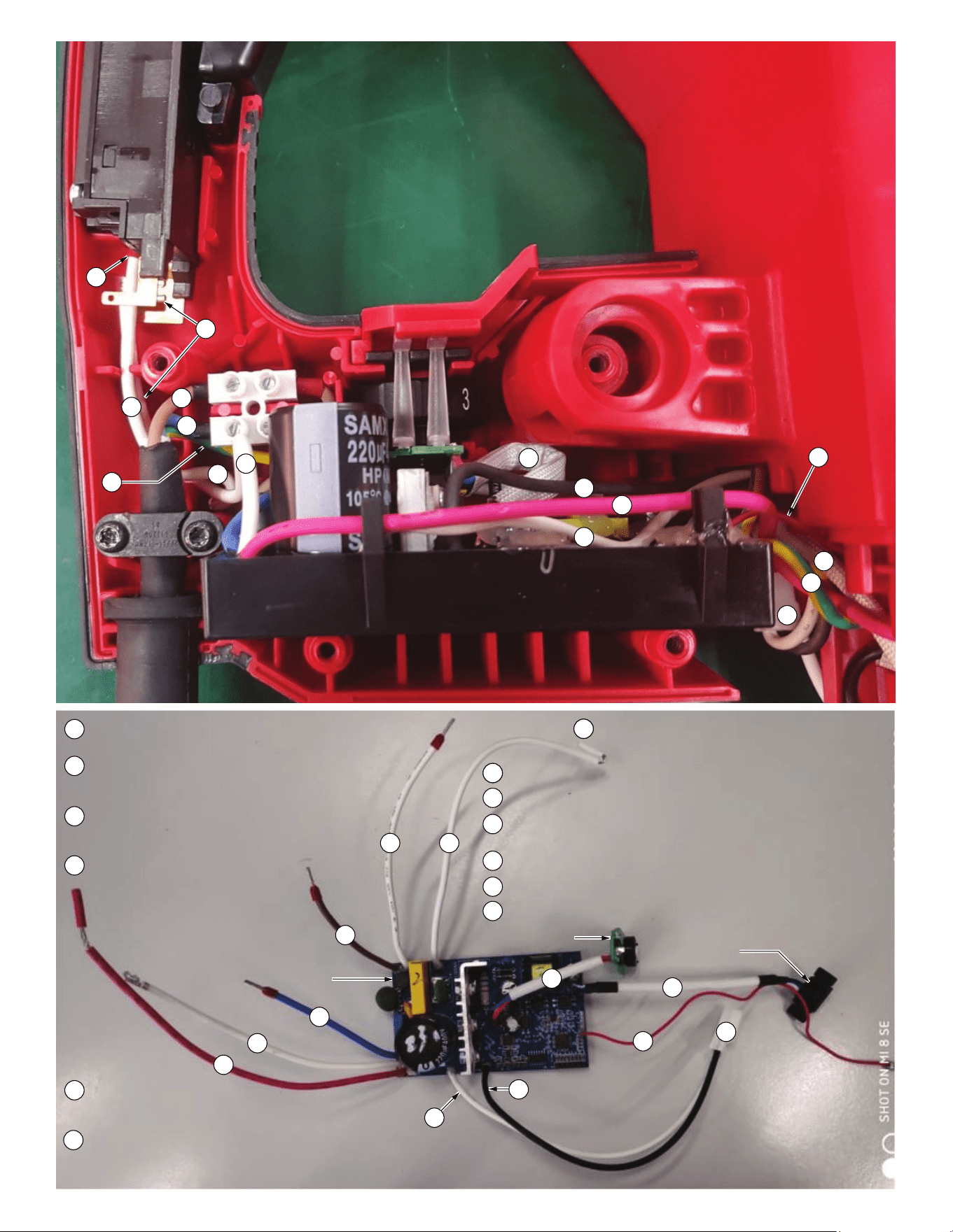
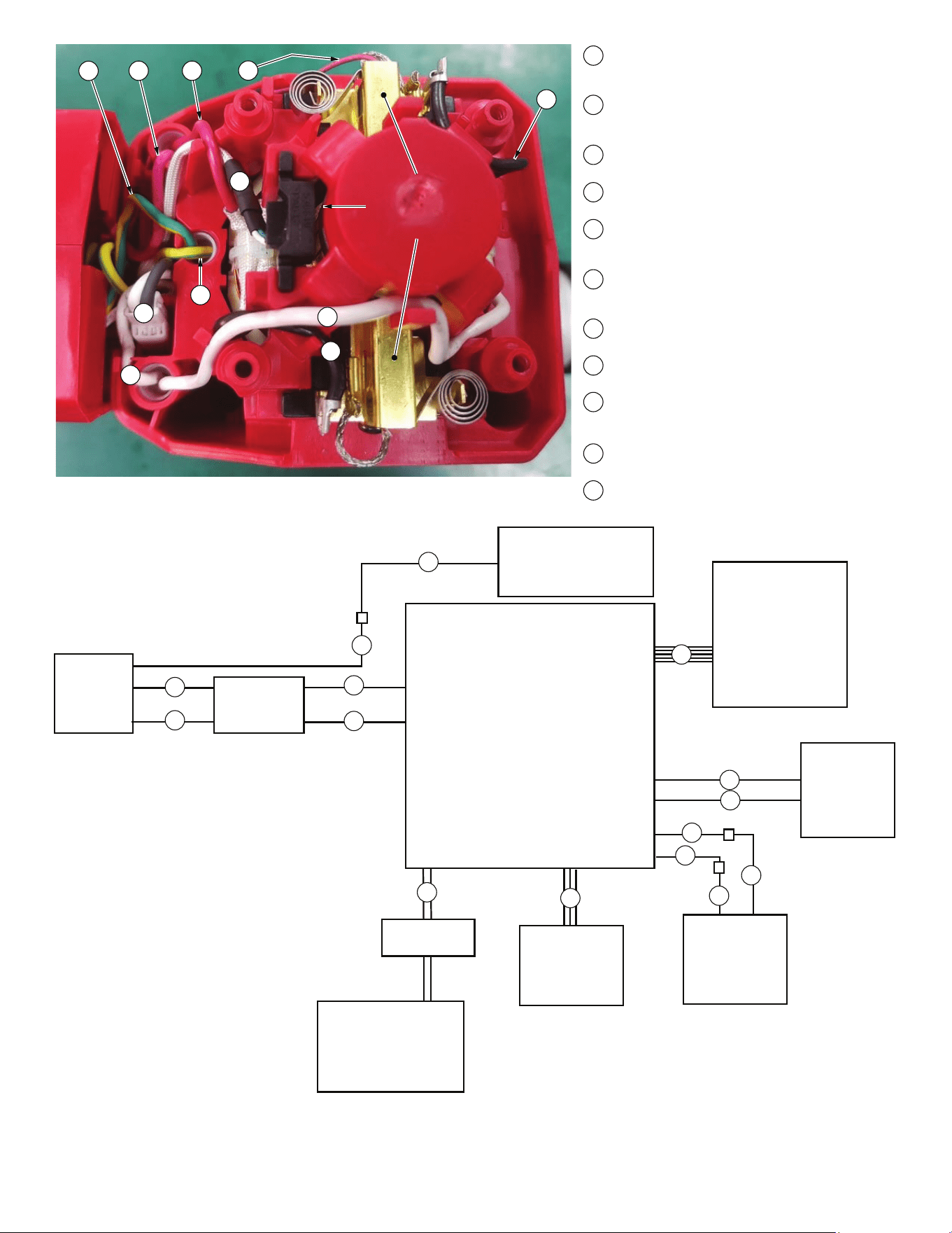
CONTROL
BOARD
UI/ SPEED DIAL HALL SENSOR
BOARD
6
5
3
1
BROWN From Control Board to top of connector block,
opposite to power cord wire #11 (brown or white).
BLUE From Control Board to bottom of connector
block, opposite to power cord wire #12
(blue or black).
BLK & From Control Board. Both black and white
WHITE wires are terminated together. Connect
with black & white wires from EM clutch.
RED From Control Board, connect
with red wire #19 from right
brush.
WHITE, From Control Board
BLUE, to Hall Sensor Board.
BLACK
YEL, RD, From Control Board to ‘U’ Board.
BLUE,
BLACK,
ORANGE
3
4
4
5
5
6
7
WHITE From Control Board, connect to white field
wire #14 using closed end connector.
7
7
WHITE From Control Board, connect to on-off switch at position 1.
WHITE From Control Board, connect to on-off switch at position 1.
RED From Control Board, connect to red field wire #16 using
closed end connector.
BROWN From Power Cord to connector block opposite wire #1.
BLUE From Power Cord to connector block opposite wire #2.
GRN/Y From Power Cord to connect to green/yellow wire #17.
8
9
10
11
12
13
14
7
1610
5
3
17
13
15
18
19
MOTOR
HOUSING
BOTTOM VIEW
Right Brush Holder
Hall Sensor
Left Brush Holder
5
7
10
13
BLK & From Control Board. Both black and white
WHITE wires are terminated together. Connect
with black & white wires from EM clutch.
WHITE, From Control Board to Hall Sensor Board.
BLUE,
BLACK
WHITE From Control Board, connect to white
field wire #14 using closed end connector.
RED From Control Board, connect to red field
wire #16 using closed end connector.
GRN/Y From Power Cord to connect to green/
yellow wire #17 using closed end
connector.
WHITE From Field, connect to white wire #7 from
control board assembly using closed end
connector.
BLACK From Field, connect to left brush holder
assembly.
RED From Field, connect with red wire #11
using closed end connector.
GRN/Y Ground wire assembly, connect to
green/yellow wire #13 using closed end
connector.
BLACK From Field, connect to right brush holder
assembly.
RED From Right Brush, connect to red wire #4
from control board.
3
14
15
16
17
18
19
POWER
CORD
CONNECTOR
GEARCASE
CONTROL
BOARD
CONNECTOR
EM-CLUTCH
HALL
SENSOR
FIELD
USER INTERFACE
PCBA
SPEED
DIAL
SWITCH
17
13
11
12
2
1
7
8
7
14
10
16
3
6
5