
30
58-01-1280
54-24-5362
B03C
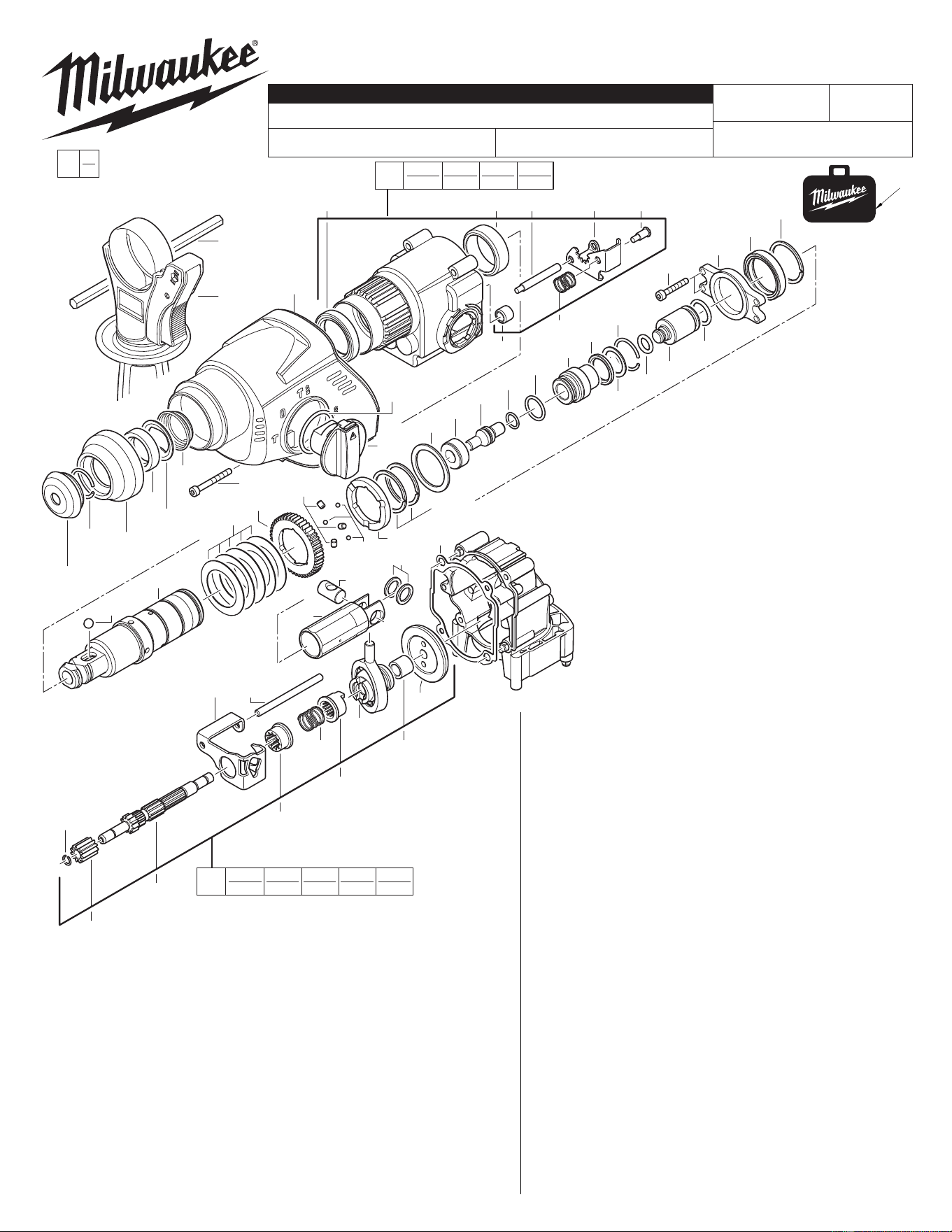
1" COMPACT SDS ROTARY HAMMER
5363-21
Dec. 2012
SEE PAGE 3 FOR IMPORTANT SERVICE NOTES
REVISED BULLETIN
SERVICE PARTS LIST
BULLETIN NO.
CATALOG NO.
SPECIFY CATALOG NO. AND SERIAL NO. WHEN ORDERING PARTS
WIRING INSTRUCTION
STARTING
SERIAL NO.
DATE
MILWAUKEE ELECTRIC TOOL CORPORATION
13135 W. LISBON RD., BROOKFIELD, WI 53005
Drwg. 2
EXAMPLE:
Component Parts (Small #) Are Included
When Ordering The Assembly (Large #).
00
0
54-24-5361
705
605
1207
343
341
344
347
349
215
218
263
270
203
230
257
246
243
242
244
1220
213
302
308 305
307
306
201
1211
1210
1217
236
248
253
216
1222
214
239
1205
1221
237
1226
1211
1212
1218
1209
208
1219
1235
209
225
241
224
1216
271
262
1204
1203
350
FIG. PART NO. DESCRIPTION OF PART NO. REQ.
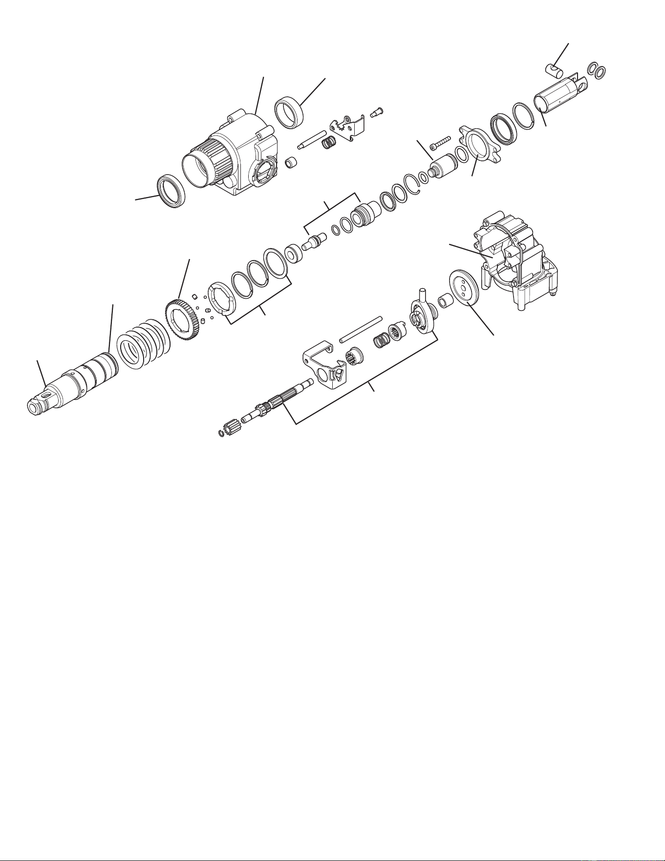
201 02-50-2183 Needle Bearing (1)
203 34-40-0186 Gear Box Housing Cover (1)
208 45-56-0076 Ram (1)
209 44-62-0055 Cylinder (1)
213 44-10-0670 Switch Handle (1)
214 44-60-0756 Pin (1)
215 40-50-0883 Spring (1)
216 44-90-0500 Shift Ring (1)
218 36-92-0583 Wobble Plate (1)
224 44-60-0483 Wrist Pin (1)
225 45-88-0283 Washer (2)
230 32-75-0041 Spindle (1)
236 45-88-0485 Washer (1)
237 44-66-0085 Endplate Assembly (1)
239 45-22-0705 Sleeve (1)
241 42-70-0040 Clutch Disc (1)
FIG. PART NO. DESCRIPTION OF PART NO. REQ.
242 44-96-0183 Clutch Roller (3)
243 32-75-1283 Spindle Gear (1)
244 02-04-0683 Ball (3)
246 40-50-0983 Belleville Spring (Five Required) (5)
248 45-88-1770 Stop Washer (1)
253 45-08-0480 Striker (1)
257 02-02-0275 7 mm Ball (1)
262 44-90-0375 Snap Ring - External (1)
263 40-50-8045 Spring (1)
270 42-36-1755 Support Plate (1)
271 44-90-0830 Holding Ring (1)
301 31-40-0055 Gear Box Assembly (1)
302 02-50-0050 Needle Bearing (1)
305 44-90-0835 Locking Plate (1)
306 44-60-1105 Spring Guide Pin (1)
307 40-50-0800 Pressure Spring (1)
308 44-60-1110 Guide Pin (1)
340 32-60-0026 Reduction Gear Assy (1)
341 36-66-0185 Reduction Gear Shaft (1)
343 32-60-0140 Gear (1)
344 32-60-0145 Internal Gear (1)
347 45-22-0610 Coupling Sleeve (1)
349 45-36-1700 Spacer (1)
350 32-05-0011 Bevel Gear (1)
605 43-46-0172 Depth Gauge (1)
705 14-46-0015 Side Handle Assembly (1)
1200 14-46-0076 Maintenance Set (1)
1203 42-52-0420 Rubber Sleeve (1)
1204 42-96-0210 Sleeve (1)
1205 34-40-1305 O-Ring (1)
1207 34-40-0010 Seal Ring (1)
1209 34-40-4466 O-Ring (1)
1210 43-44-0875 Seal (1)
1211 44-90-0350 Snap Ring - External (3)
1212 05-78-0041 M4 x 24 Thread Form Screw (8)
1216 34-40-1025 O-Ring (1)
1217 42-76-0830 Thrust Collar (1)
1218 34-40-4451 O-Ring (1)
1219 34-40-0130 O-Ring (1)
1220 05-78-0031 M4 x 38 Thread Form Screw (4)
1221 44-90-0183 Retaining Ring - Internal (1)
1222 34-40-0430 Spring Ring (1)
1226 44-90-0347 Damping Ring (1)
1235 34-40-0445 O-Ring (1)
30 48-55-0077 Molded Carrying Case, Optional (1)
301
302
1207
305
308
307
306 201
340
1222
343
344
341
215
347
218
350349
NOTE: Items #214 and #216 are not
components of #340
1234
231
1213
1232
110
1215
223
205
220
221
1237
1215
106
107
108
1202
204
1223
127
222
104
105
100
103
138
1230
127
1201
1201
150
135
8
1238
1238
1212
156
1231
1208
152
1229
153
151
1228
1214
1214
120
119
1239
4
125126
1240
FIG. PART NO. DESCRIPTION OF PART NO. REQ.
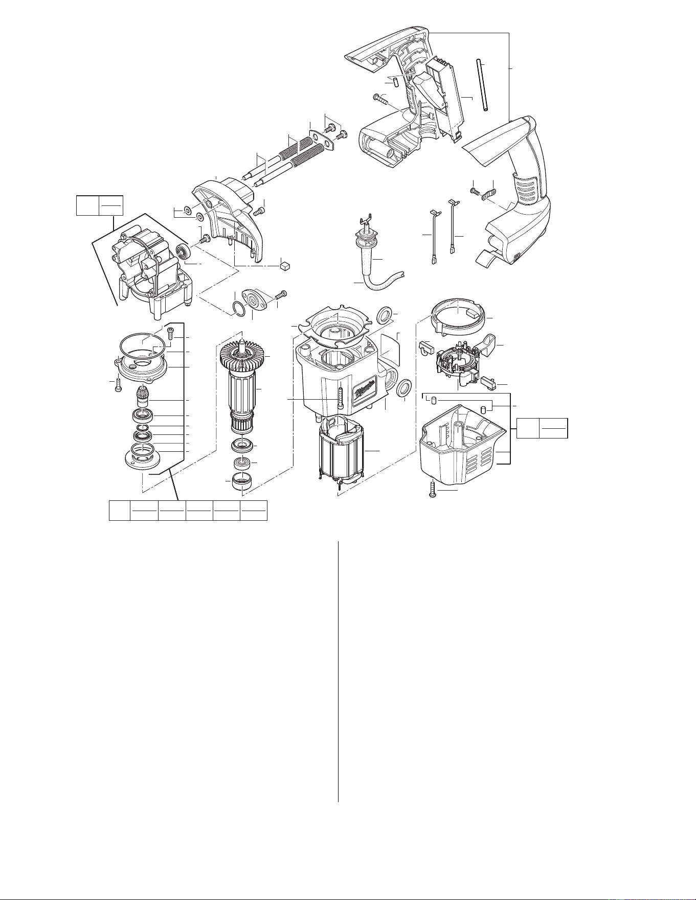
4 22-64-1622 Cord Set (1)
8 12-20-5363 Service Nameplate (1)
100 31-40-5363 Motor Housing (1)
102 31-15-0060 Cover Assembly (1)
103 22-22-0070 Brush Carrier (1)
104 31-05-0095 Air Defl ector Ring (1)
105 18-07-0015 Service Field (1)
106 16-07-0015 Service Armature (1)
107 22-84-0040 Fan (1)
108 02-04-1801 Ball Bearing (1)
110 45-88-9000 Insulating Disc (1)
119 23-94-0155 Wire (1)
120 23-94-0175 Wire (1)
125 31-17-0240 Cord Clamp (1)
126 05-78-0720 Screw (2)
127 05-78-0715 Screw (7)
135 23-66-0405 Switch (1)
138 22-22-0075 Brush Carrier (1)
150 14-38-0115 Handle Assembly (1)
151 44-66-0540 Bearing End Plate (1)
152 02-04-0090 Ball Bearing (1)
153 32-60-0016 Pinion (1)
156 42-92-0165 Bearing Cover (1)
160 44-66-1147 Bearing End Plate Assembly (1)
202 31-15-0106 Gear Box (1)
204 02-04-0056 Ball Bearing (1)
FIG. PART NO. DESCRIPTION OF PART NO. REQ.
205 31-15-0760 Gearbox Cover (1)
220 44-60-0205 Guide Pin (2)
221 44-90-0070 Latch Plate (1)
222 40-50-0505 Spring (2)
223 45-88-0875 Washer (2)
231 42-92-1520 Bearing Cover (1)
1200 14-46-0076 Maintenance Set (1)
1201 22-18-0010 Carbon Brush Set (1)
1202 42-96-0205 Rubber Sleeve (1)
1208 45-06-0095 Seal Ring (1)
1213 34-40-0083 O-Ring (1)
1214 05-78-0051 M4 x 12 Thread Form Screw (3)
1215 05-74-0220 Screw (3)
1223 05-78-0051 M4 x 12 Thread Form Screw (2)
1228 34-40-0435 O-Ring (1)
1229 45-88-1775 Spring Ring (1)
1230 45-30-0055 Slug (2)
1231 34-40-0440 O-Ring (1)
1232 05-74-0460 Cap Screw (2)
1234 43-84-0443 Felt (1)
1237 45-30-0215 Vinyl Slug (1)
1238 34-40-0063 O-Ring Motor Housing (2)
1239 44-76-0075 Cord Protector (1)
1240 45-30-0075 Rubber Slug (1)
1241 05-74-0715 Screw (2)
49-08-5350 Type "P" Grease (100 g) (1)
49-08-4255 Type "Q" Grease (45 g) (1)
102
1230
202
204
160
1228
1214
153
151
152
1229
1231
1208 156
1241

Service Notes:
Disassembly:
220, 1215 Remove screw (s) (1215) from guide bolts (220) evenly to release spring tension.
202, 220 Remove guide bolts (220) from gearbox (202) using a 4mm hex key.
203, 213 When, removing shift lever (213) from gear case cover (203) follow instructions listed on service bulletin. [see fi g. 1]
202, 203, 301 Release locking tabs on gearbox cover (203) when removing from gearbox assembly (301and 202). [see fi g. 3]
301, 308 Remove guide bolt (308) from gearbox (301) using a 3mm hex key
106, 152, 153 Remove armature pinion (153) from armature (106) using Special Service Fixture 61-10-0025.
Note: Place separator plates 61-10-0011 under ball bearing (152) as illustrated in fi g. 5.
230, 243, To remove retaining ring (1211) from spindle (230) use service fi xture 61-30-0290.
246, 1211 Note: Spindle gear / clutch gear (243) must be compressed against Belleville spring washers (246) before retainer can be removed
with a pair of retaining ring pliers. (see fi g.8)
105, 138 To remove brush carrier (138) from fi eld (105) you must lift brush carrier locking tabs at the front and back of the fi eld board on both
sides while applying a light upward force on the carrier.
Reassembly:
105, 138 To reassemble brush carrier (138) onto fi eld (105) you must align male prongs of carrier with female mag-mate terminals on the fi eld
and push brush carrier down until locking tabs on the brush carrier lock onto the fi eld board.
248, 253 Small diameter end of striker (253) must face stop washer (248) in assembly.
230, 248 Chamfer side of stop washer (248) must face front of spindle (230).
202, 237 Raised bosses on end plate assembly (237) must face gearbox (202) in assembly
203, 213 When, reinstalling shift lever (213) into gearcase cover (203) follow instructions shown in fi g. 2.
220, 306, 308 Apply Blue Loctite ® METCo part # 44-22-0090 to fasteners listed if removed and being reinstalled.
1212, 1214, 1215 New fasteners in service kit will not require Loctite®.
1220, 1223, 1232
262, 271 Taper of holding ring (271) must face spring ring (262) in assembly.
263, 270 Wide portion of conical spring (263) must face plate (270).
341, 349,350 When reassembling bevel gear (350) onto reduction gear shaft (341) a .001 to .002 clearance must be maintain between bevel gear
(350) and spacer (349).[see fi g.4]
152, 1208 Flared edge of seal (1208) must face ball bearing (152) in assembly.
246 Reassemble, Belleville Spring washers as illustrated in fi g. 7.
106, 107 When replacing a fan (107) on armature assembly (106), refer to illustration shown in fi g. 6 for press dimensions.
341, 1222 Install a new spring ring retainer (1222) if removed from reduction gear shaft (341).
NOTE: Check the clutch torque. Clutch must slip at 17 to 26 ft. lbs. at the spindle, checked clockwise as viewed from the front of the tool.
Selector knob must be set to the hammer only setting.
Service Kit 14-46-0076 Contains:
Cat. No. Description Qty.
22-18-0010 Carbon Brush Set (1)
42-96-0205 Rubber Sleeve (1)
42-52-0420 Rubber Sleeve (1)
42-96-0210 Sleeve (1)
34-40-1305 O-Ring (1)
34-40-0010 Seal Ring (1)
45-06-0095 Seal Ring (1)
34-40-4466 O-Ring (1)
43-44-0875 Seal (1)
44-90-0350 Snap Ring - External (3)
05-78-0041 M4 x 24 Thread Form Screw (8)
34-40-0083 O-Ring (1)
05-74-0715 Socket Head Screw - Plast. (2)
05-74-0220 Screw (3)
34-40-1025 O-Ring (1)
42-76-0830 Thrust Collar (1)
34-40-4451 O-Ring (1)
34-40-0130 O-Ring (1)
05-78-0031 M4 x 38 Thread Form Screw (4)
44-90-0183 Retaining Ring - Internal (1)
34-40-0430 Spring Ring (1)
05-78-0051 M4 x 12 Thread Form Screw (5)
44-90-0347 Damping Ring (1)
34-40-0435 O-Ring (1)
45-88-1775 Spring Ring (1)
45-30-0055 Slug (2)
34-40-0440 O-Ring (1)
05-74-0460 Cap Screw (2)
43-84-0443 Felt (1)
34-40-0445 O-Ring (1)
45-30-0215 Vinyl Slug (1)
34-40-0063 O-Ring Motor Housing (2)
49-08-5350 Type "P" Grease (100 g) (1)
49-08-4255 Type "Q" Grease (45 g) (1)
44-76-0075 Cord Protector (1)
45-30-0075 Rubber Slug (1)
BULLETIN NO. 54-24-5362 Mar. 2009 PAGE 3 OF 6
Lubrication
Type "Q" Grease, No. 49-08-4255 (4931 6243 75)
Coat with a total of 1/4 oz.
Type "P" Grease, No. 49-08-5350 (4931 3757 90)
Coat with a total of 1-3/4 oz.
Place approx.
3/4 oz Type "P"
Place approx.
1/4 oz Type "P"
Place approx.
1/2 oz Type "P"
Coat with
Type "P"
Coat with
Type "P"
Coat with
Type "P"
Coat with
Type "Q"
Coat with
Type "P"
Coat with
Type "P"
Coat with
Type "Q"
Coat with
Type "Q"
Coat with
Type "Q"
Coat with
Type "P"
Coat with
Type "P"
Coat with
Type "P"
Torque Specifi cations
Screws in plastic, 15 in. lbs.
Screws in metal, 22 in. lbs. Use Blue Loctite® 242, Cat. No. 44-22-0090
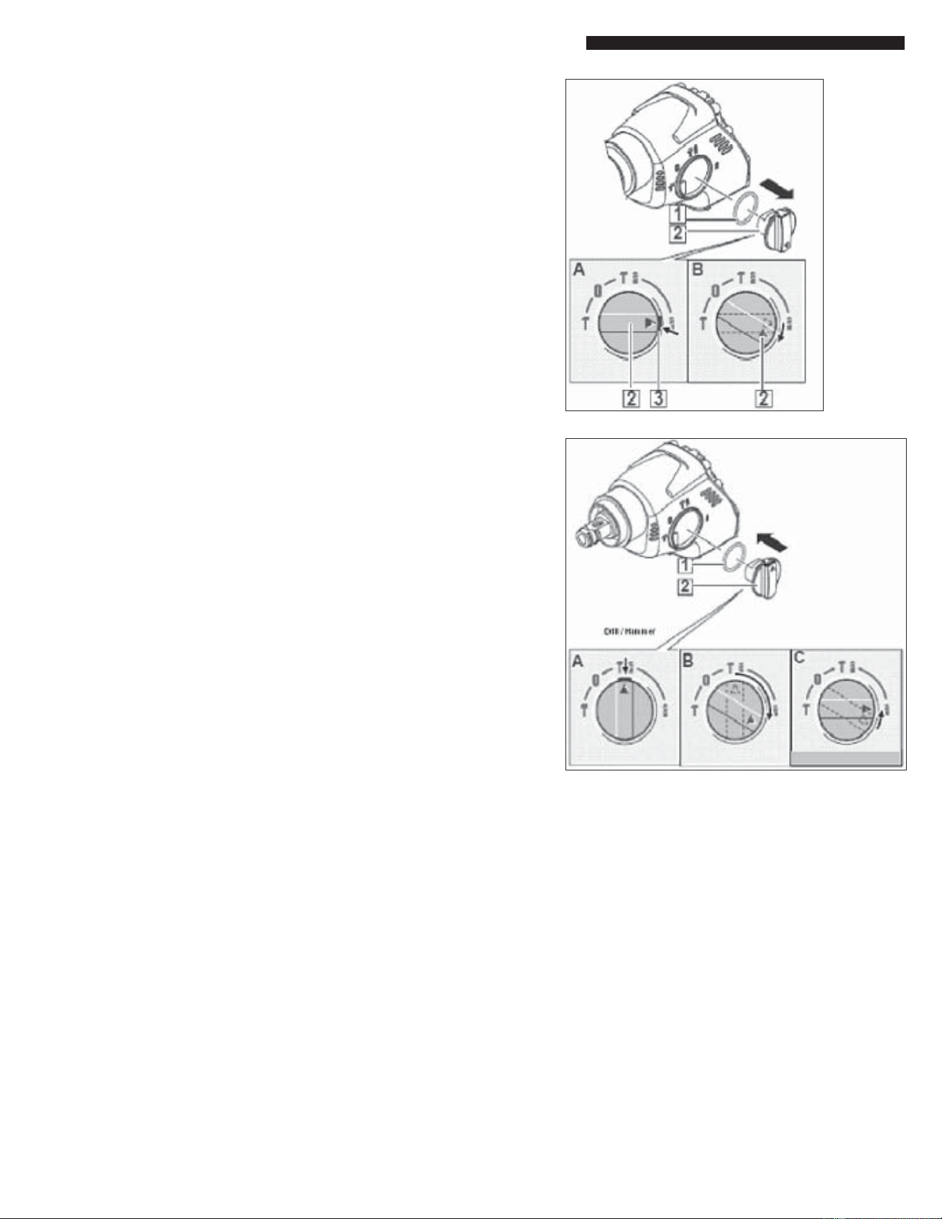
Fig. 1
Fig. 2
Removing the 1 Bring the shift lever (2) into the
shift lever Drill-Only position (Illustration A).
2 Press in and hold the locking
device (3) (Illustration A) and turn
the shift lever past the drill icon
(Illustration B) until the shift lever (2)
can be pulled from the housing.
3 Remove the O-ring (1).
Installing the 1 Lightly grease the O-ring (1) and
shift lever install it into the Shift Lever (2).
2 Position the triangle located on
the shift lever to the Hammer / Drill
icon and insert it into the gearcase
(Illustration A). Press the locking
device and turn clockwise
(Illustration B) until the shift lever (2)
engages audibly. After that, turn
it back to the required position (C)
and release the locking device.
BULLETIN NO. 54-24-5362 Mar. 2009 PAGE 5 OF 6
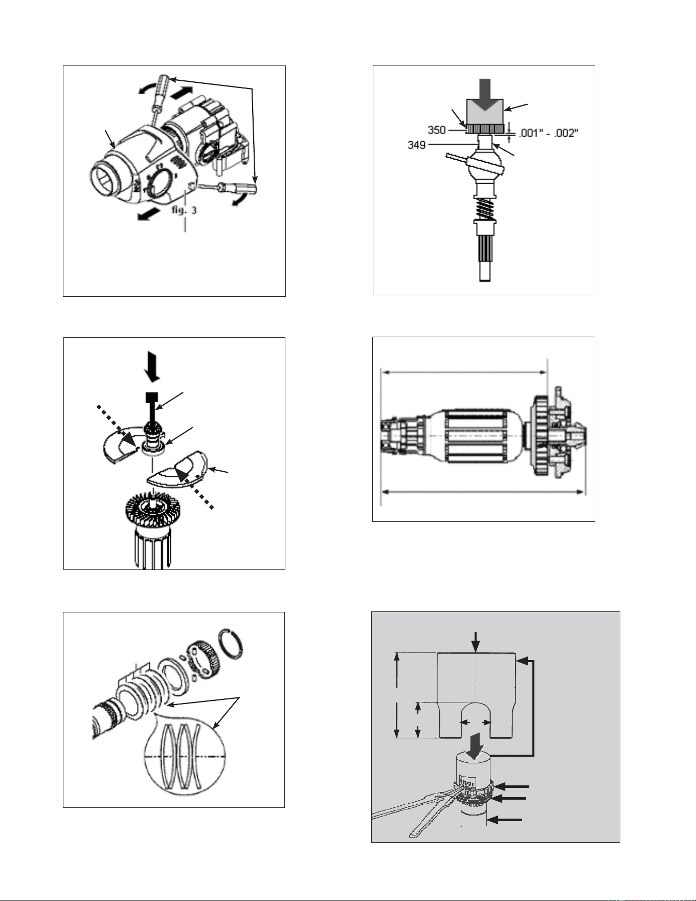
Fig. 3
Gearbox
Housing
Cover
Flat Blade
Screwdrivers
Put screwdrivers under the "lugs" of the
gearcase insulation, widen it, and push
the gearcase insulation from the tool.
Fig. 4
Bevel Gear
Press Cylinder
Spacer
Fig. 5
Service Fixture
61-10-0025
Press
Service
Fixture
61-10-0011
Armature Pinion
Ball Bearing
Fig. 6
Press-on measurements:
Press-on measurement fan: 4.877 - 4.885
Press-on measurement pinion: 5.814 - 5.815
Fig. 7
Belleville
Spring
Washers
246
Fig. 8
3.00
1.25
.75
Press
Service Fixture
61-30-0290 shown
with two opposing
sections removed.
Spcifi cations for
fi xture shown.
Belleville Spring
Washers
Spindle Gear
Spindle