

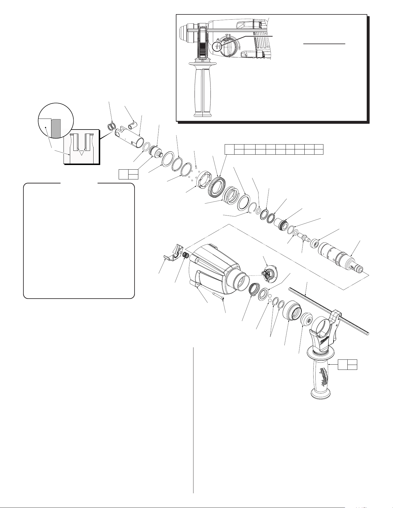
1" D-HANDLE ROTARY HAMMER
54-24-5264
Oct. 2024
See page 6
REVISED BULLETIN
SERVICE PARTS LIST
BULLETIN NO.
WIRING INSTRUCTION
DATE
EXAMPLE:
Component Parts (Small #) Are Included
When Ordering The Assembly (Large #).
0
00
SPECIFY CATALOG NO. AND SERIAL NO. WHEN ORDERING PARTS
MILWAUKEE ELECTRIC TOOL CORPORATION
13135 W. LISBON RD., BROOKFIELD, WI 53005
Drwg. 2
l= Component of the 14-46-5265
5262-21 Maintenance Service Kit
SEE PAGE TWO FOR THE PROCEDURE
ON CHECKING THE STATIC SLIP
VALUES OF THE CLUTCH
54-24-5263
FIG. PART NO. DESCRIPTION OF PART NO. REQ.
17 14-13-0060 Diaphragm Assembly w/ Bushing (1)
17a 43-44-1375 Gasket (1)
17c --------------- Diaphragm w/ Bushing (1)
17d 43-84-0300 Felt Plug (1)
17e 45-06-5263 Seal Ring (1)
18 05-78-0105 M4 x 10mm Pan Hd. Tapt. T-20 Screw (2)
19 16-10-0102 120V Armature Assembly (1)
19a 02-04-0039 Ball Bearing (1)
19b 44-66-0117 Bearing Retaining Plate (1)
19c --------------- Armature (1)
19d 02-04-5382 Ball Bearing (1)
20 05-78-5313 M4 x 9mm Pan Hd. Plast. T-15 Screw (4)
21 42-14-0112 FanBae (1)
22 18-01-0032 120V Field Assembly (1)
23 28-50-0052 Motor Housing (1)
24 22-20-0029 Brush Holder (2)
24a --------------- Brush Spring (2)
25 05-88-0030 M3 x 8.5mm Pan Hd. ST T-10 Screw (4)
26 22-18-0032 120V Carbon Brush (2)
27 23-94-0033 Leadwire Assembly-Red (See page 5) (1)
28 23-94-0037 Leadwire Assembly-Blue (See page 5) (1)
29 36-92-0010 Reduction Gear Assembly (1)
29a 44-90-1180 C-Ring (1)
29b 32-60-1611 2nd Stage Pinion (1)
29c --------------- Reduction Gear Shaft (1)
29d 45-22-0927 Coupler (1)
29e 40-50-2141 Shift Spring (1)
29f 45-22-0926 Wobble Coupler (1)
29g 36-92-5263 Wobble Bearing (1)
29h 32-75-0027 1st Stage Gear (1)
29j 44-66-0022 Retaining Plate (1)
29k 02-04-5385 Ball Bearing (1)
29m 06-82-0017 M4 x 10mm T-15 Screw (1)
30 14-34-0025 Housing Assembly (1)
30a 06-82-0995 M4 x 16mm Pan Hd. Plast. T-20 Screw (10)
19d
30b
30a
(10x)
35
25
(4x)
26
(2x)
24a
(2x)
24a
24
31
30e
(2x)
32
33
(2x)
23
30c
34a
34a
34
30d
22
21
20
(4x)
19c
19b
18
(2x)
19a
17e
17d
17c
29m
29j
29g
29k
36
(2x)
29h
29f
29e
29d
29c
17a
29b
29a
19a 19b 19c
19d 42
19
17c 17d
17e
17
30a 30b
30d 30e
30
29a 29b 29c 29d 29e 29f
29g 29h 29j 29k 29m
29
24 25
26
41
42
No breather
hole in diaphragm
Breather hole
with rubber sleeve
and 2nd felt plug
Design 2
Design 1
NOTE:
There are two different designs
for service replacement 14-13-
0060 Diaphragm Assembly (17).
Both designs are directly
interchangeable.
FIG. PART NO. DESCRIPTION OF PART NO. REQ.
30b --------------- Housing Halve - Right (1)
30c 45-34-0017 Forward/Reverse Lever (1)
30d --------------- Housing Halve - Left (1)
30e 44-52-0025 Foam Pad (2)
31 23-66-0013 120V Switch (1)
32 42-68-0601 Cord Clamp (1)
33 05-78-5313 M4 x 9mm Pan Hd. Plast. T-15 Screw (2)
34 22-64-0027 120V Power Cord (1)
34a 44-76-0210 Strain Relief (1)
35 12-20-5261 Service Nameplate (1)
36 05-74-1030 M5 x 8mm Pan Hd. Tapt. T-25 Screw (2)
40 42-55-5263 Blow Molded Carrying Case (1)
41 22-22-0043 Brush Service Kit (Set of 2) (1)
42 23-16-0092 Commutator Insulator (1)
l
l
l
l
l
40
CATALOG NO. 5262-21
SERIAL NO.
G43C
33
l= Component of the 14-46-5265
5262-21 Maintenance Service Kit
FIG. PART NO. DESCRIPTION OF PART NO. REQ.
1 14-34-5262 Auxilary Side Handle Assembly (1)
1a 44-94-5381 Depth Gage Rod (1)
2 42-52-5262 Rubber Cap (1)
3 31-58-0037 Chuck Sleeve (1)
4 44-90-0014 C-Ring (2)
5 02-02-0275 Steel Ball (2)
6 42-36-0191 Ball Plate (1)
7 40-50-5262 Conical Spring (1)
8a 28-14-0013 Gearcase
w/ Bushing, Bearings, Seal & Screw
(1)
8d 44-90-1011 Lock Plate (1)
8e 40-50-0870 Lock Plate Spring (1)
9 44-10-5264 Shift Knob Assembly (1)
10 32-75-0021 SDS Spindle and Gear Assembly (1)
10a 38-50-0048 SDS Spindle (1)
10b 43-06-0040 Brake Ring (1)
10c 34-40-1425 O-Ring (1)
10d 45-22-0870 Anvil Sleeve (1)
10e 34-40-0018 O-Ring (1)
10f 34-40-1410 O-Ring (1)
10g 45-08-0650 Anvil (1)
10h 34-40-1440 O-Ring (1)
10j 42-76-1001 Washer (1)
10k 44-90-1026 Snap Ring (1)
l
l
l
l
l
l
l
l
To check the static slip values of the
clutch you must do the following:
• Position Red spring loaded shifting
lever at the hammer only icon.
• Lock motor housing of tool into the
jaws of a vise having brass jaws or
the equivalent.
• Insert a SDS Plus adaptor* into spindle.
• Turn torque wrench clockwise as viewed from the front of the
tool until the single slip cycle has been accomplished. Observe
the torque reading. Slip clutch a minimum of three times for the
most accurate reading.
*SDS Plus Adaptor being used is made by threading a ½” x 20
hex nut onto the threads of SDS adaptor No. 48-03-3005.
Note: Apply RED Loctite to threads of hex nut prior to tightening.
Max = 240in/lbs or 20ft/lbs • Min = 150in/lbs or 12.5ft/lbs
FIG. PART NO. DESCRIPTION NO. REQ.
10m 45-88-2115 Washer (1)
10n 40-50-1721 Clutch Spring (1)
10p 32-75-1831 2nd Stage Gear (1)
10q 42-70-0786 Clutch Plate (1)
10r 02-02-7045 Steel Ball (6)
10s 44-90-0216 C-Ring (Thicker then 10t) (1)
10t 44-90-0215 C-Ring (1)
11 45-88-0026 Washer (1)
12 45-56-0037 Striker Assembly (1)
12a 34-40-1511 O-Ring (1)
12b --------------- Striker (1)
13 44-62-0058 Piston (1)
14 45-88-5200 Washer (2)
15 44-60-0033 Wrist Pin (1)
16 06-81-5383 M4 x 35mm Pan Hd. Plast. T-20 Screw (4)
l
l
l
l
l14-46-5265
Rotary Hammer Service Kit
2 42-52-5262 Dust Cap (1)
3 31-58-0037 Chuck Sleeve (1)
4 44-90-0014 C-Ring (2)
10c 34-40-1425 O-Ring (1)
10e 34-40-0018 O-Ring (1)
10f 34-40-1410 O-Ring (1)
10h 34-40-1440 O-Ring (1)
10k 44-90-1026 Snap Ring (1)
10s 44-90-0216 C-Ring (Thicker) (1)
10t 44-90-0215 C-Ring (Thinner) (1)
12a 34-40-1511 O-Ring (1)
14 45-88-5200 Washer (2)
17a 43-44-1375 Gasket (1)
26 22-18-0032 Carbon Brush (2)
29a 44-90-1180 C-Ring (1)
29m 06-82-0017 M4.0 x 0.7 Screw (1)
36 05-74-1030 Taptite Screw (2)
49-08-5355
'Q2' Grease 2.8 oz. tube
(1)
49-08-5262
‘S2’ Grease 1.4 oz. tube
(2)
14
(2x)
15
13
12a
12b
11
10t
10s
10r
(6x)
10q
10p
10n
10m
10k
10e
10j
10h
10d
10c
10b
10a
10f
10g
2
3
4
(2x)
5
(2x)
7
16
(4x)
6
8a
1a
9
8e
8d
1a
1
12a
12b
12
10a 10b 10c 10d 10e 10f 10g 10h 10j
10k 10m 10n 10p 10q 10r 10s 10t
10
14
13
IMPORTANT:
Rounded side of Washers (14)
must be placed facing the inside
surface of Piston (13) as shown.
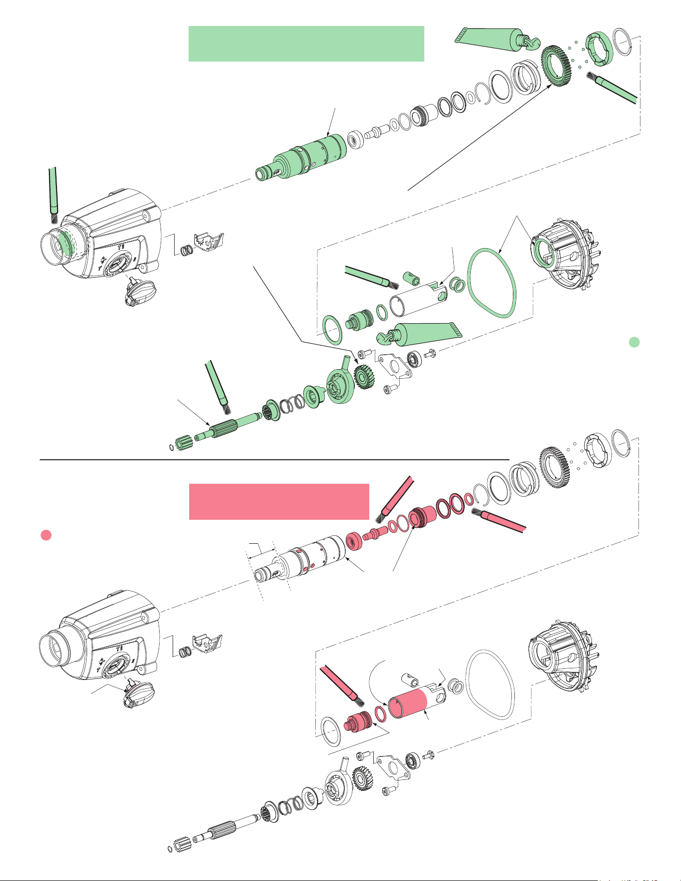
Prior to reinstalling,
clean gear assemblies
with a clean, dry cloth.
Lightly coat all parts highlighted here
with ‘S2’ grease. Apply a greater amount
of grease to all internal and external gear teeth.
LUBRICATION NOTES:
Type ‘Q2’ Grease
No. 49-08-5355, 2.8 oz. / 80g tube
Approximately .3 oz. /8.7g needed
LUBRICATION NOTES:
Type ‘S2’ Grease
No. 49-08-5262, 1.4 oz. / 40g tube (2 included)
Approximately 2.1 oz. / 60g needed
Place a very liberal amount of
grease to the rear
of the piston.
Place a liberal amount of grease
along the whole length of the
reduction gear shaft.
Lightly coat all parts
highlighted here with ‘Q2’ grease
unless directed otherwise.
Lubrication Note: MILWAUKEE recommends that sched-
uled maintenance of this Rotary Hammer include lubrication
replacement, and replacement of vital O-rings and gaskets
at each carbon brush change. Doing so will prolong the life
of the hammer by reducing wear to gears and mechanism
parts. The carbon brushes and armature commutator in this
MILWAUKEE Rotary Hammer are designed and matched
for many hours of reliable performance.
Coat the o-ring
on the shift lever
with grease.
There is to be no grease
on the face of the ram.
Place approx. 27.5 grams, (1.0 oz.) of ‘S2’ grease
on the spindle gear and bevel gear once the
spindle sleeve and gear assembly
and reduction gear assembly
are installed into the
diaphragm
assembly.
Coat the inside cavity
of the sleeve and spindle
with ‘Q2’ grease.
Apply a very light film of grease
on the side wall of piston. There
is to be no grease
on the back wall.
Lightly coat exterior
of piston.
Lightly coat the exterior
of the entire spindle
Lightly coat the
gasket and bushing
No grease in this
area of spindle
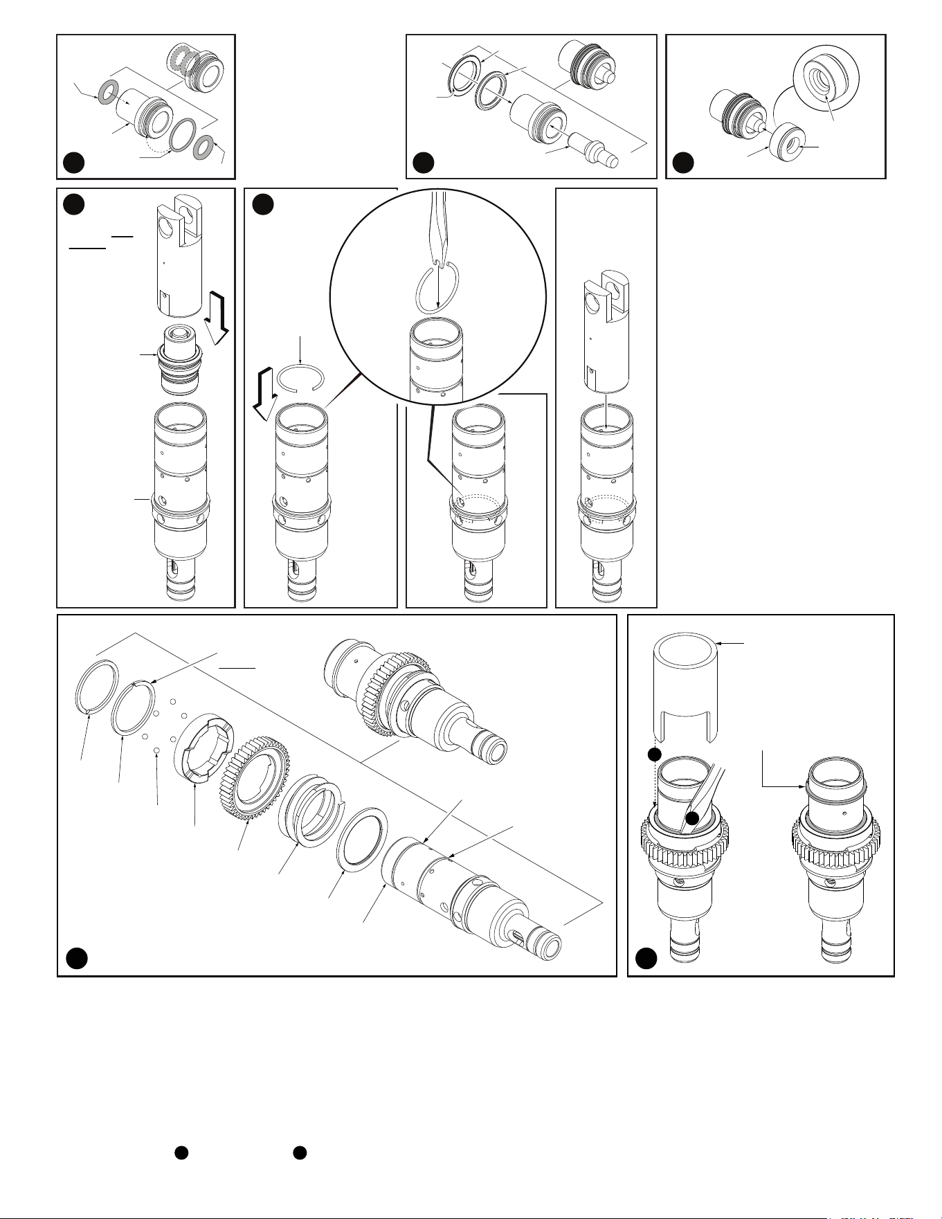
Chamfer
Deep
recess
Chamfer side of 9h
facing assembly
10b
10e
10d
10c
10j
10h
Larger end into
Ram Catcher
Use an old
piston to help
squarely push
the internal
components
into spindle.
Assembled
components:
10b, 10c, 10d,
10e, 10f, 10g,
10h and 10j.
10a Spindle
10k C-Ring
Use the same
old piston to
seat C-Ring
into internal
spindle groove.
Modified
screwdriver
with notch.
Push C-Ring
into spindle
cavity and
rotate as
shown.
Assembly of internal Spindle
components:
1. Lubricate Ram Catcher and O-Rings.
Assemble O-Rings onto and into
Ram Catcher.
2. Assemble Anvil Assembly into Ram
Catcher Assembly (large end into
Ram Catcher as shown).
3. Place the chamfered end of the Stop
Washer over the small end of the
Anvil.
4. Place the assembled components
from step 4 into the cavity of an old
piston as shown. Use the old piston
as an aid to push the assembled
components deep into the Spindle
cavity.
5. C-Ring (10k) will be used to secure
internal components inside the
spindle. It is recommended to modify
a flat blade screwdriver by filing or
grinding a notch into the blade. Place
the C-Ring upright as shown with the
opening of the ring straight up. Use
the modified screwdriver to push the
C-Ring down into the Spindle cavity.
Rotate the C-Ring in the spindle
cavity as shown.Place the old piston
into the Spindle cavity and tap the
piston with a mallet to secure the
C-Ring in the groove.
Flat
side
of Washer
towards
Ram Catcher
10f
1
3
4
2
5
10a
10m
10n
10p
10q
10r
10s
10t
Spindle Service Fixture
No. 61-30-0290
Used to compress items
10m, 10n, 10p, 10q, 10r
and 10s onto 10a.
With the aid of a snap
ring pliers, work C-Ring
(10t) into top groove.
6 7
Assembly of external Spindle components:
6. Install Washer 10m and Spring 10n onto spindle. Lubricate and install the Clutch Gear 10p and Clutch Plate 10q onto the Spindle. Be sure to orient
the part as shown and position with the three notches on the back of the plate over the holes in the spindle.
Place C-Ring 10s onto Spindle. (C-Ring 10s has a thicker cross section than C-Ring 10t.) With the aid of a snap ring pliers, work the C-Ring past the
first spindle groove down to the other parts assembled onto spindle.
7. Place Spindle Service Fixture 61-30-0290 over the assembled parts and the Spindle. Position so the fixture rests on Clutch Plate 10q. Be sure the
three notches are not covered. Place the fixture and spindle assembly in an arbor press and carefully compress the Clutch Spring enough to expose
the six holes in the Spindle. As an aid, put a dab of grease on your finger to pick up and place the six Steel Balls 10r into the six small holes on
the Spindle just above Clutch Plate. Ensure the notches in the Clutch Plate are aligned with the Steel Balls.
While compressed , use a screwdriver to work C-Ring 10s into the Spindle groove. Ensure the Steel Balls are in place and slowly retract the
arbor press. The Clutch Plate should slide over the Steel Balls until it is in contact with the C-Ring.
Place C-Ring 10t onto Spindle. With the aid of a snap ring pliers, work the C-Ring into the first spindle groove and snap into place.
A
A
B
NOTE:
C-Ring 10s is
thicker than 10t
10t in this groove
10s in this groove
B
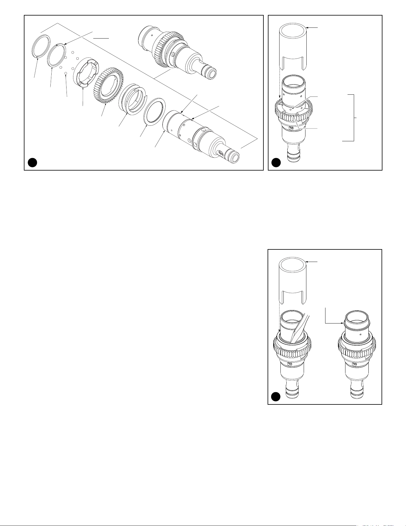
10a
10m
10n
10p
10q
10r
10s
10t
Spindle Service Fixture
No. 61-30-0290
Used to compress items
10m, 10n, 10p onto 10a.
Install six Steel Balls
10r into the six holes
on the Spindle and
remove fixture.
One of six
holes in
Spindle 10a.
One of three
flats on Clutch
Gear 10p.
8 9
Assembly of external Spindle components:
8. Install Washer 10m and Spring 10n onto spindle. Lubricate and install the Clutch Gear 10p onto the Spindle 10a.
Be sure to orient the part as shown with the three flats on the Clutch Gear centered over the holes in the spindle.
9. Place Spindle Service Fixture 61-30-0290 over the assembled parts and the Spindle. Position so the fixture rests on the Clutch Gear 10p.
Be sure the six holes on the Spindle are not covered. Place the fixture and spindle assembly in an arbor press and carefully compress
the Clutch Spring enough to expose the six holes in the Spindle.
As an aid, put a dab of grease on your finger to pick up and place the six steel balls 10r into the six small holes on the Spindle just
above the Clutch Gear.
Remove the Spindle from the arbor press.
10. Lubricate and install the Clutch Plate 10q onto the Spindle. Be sure to orient the part such that
three inside notches on the plate cover the Steel Balls in the Spindle. Place the C-Ring 10s onto
the Spindle. (NOTE: C-Ring 10s has a thicker cross-section than C-Ring 10t). With the aid of a
snap ring pliers, work the C-Ring past the first spindle groove, down to the other parts assembled
onto the spindle.
Place Spindle Service Fixture 61-30-0290 over the assembled parts and the Spindle. Place the
fixture and spindle assembly in an arbor press and carefully compress the Clutch Spring enough
to expose the C-Ring groove in the Spindle.
While compressed, use a flat blade screwdriver to work C-Ring 10s into the spindle groove.
Ensure that the Steel Balls are still in the spindle. Slowly retract the arbor press. The Clutch
Plate should slide over the Steel Balls until it is in contact with the C-Ring.
With the aid of a snap ring pliers, work C-Ring 10t into top groove of Spindle.
Center
flats
over
holes
NOTE:
C-Ring 10s is
thicker than 10t
10t in this groove
10s in this groove
Spindle Service Fixture
No. 61-30-0290
Used to compress items
10m, 10n, 10p, 10q, 10r
and 10s onto 10a.
With the aid of a snap
ring pliers, work C-Ring
(10t) into top groove.
10
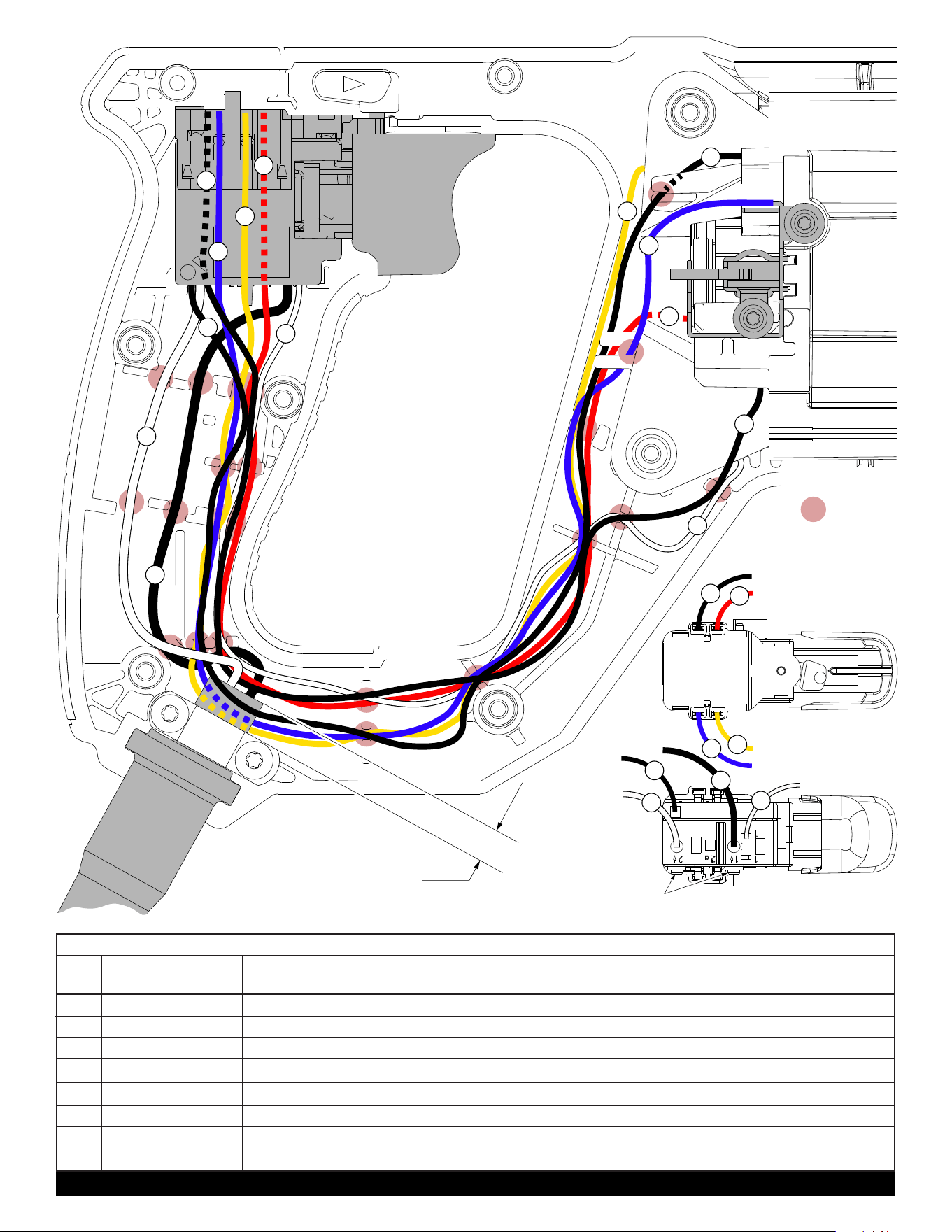
NOTE: As an aid to reassembly,
take note of the wire routings
and position of the wires in the
wire guides and traps prior to
dismantling the tool.
Watch for pinched wires when
placing the handle cover back
over the housing assembly.
Check for the proper switch
and shuttle functionality
before attempting to use
tool.
= Wire traps
or guides
2
1
3
4
4
3
5
6
6
5
7
7
8
8
NOTE:
Cord jacket is to extend approximately
.25” beyond the cord clamp area.
Switch-Top View
Switch-Bottom View
2
1
3
4
5
6
7
8
5 8
7
6
Torque screws to 6±1 kg-cm (5 in-lbs). Recheck to correct relaxation.
WIRING SPECIFICATIONS
1 White ----- ----- Component of cord set. Connect to '2â' position on bottom of switch.
2 Black ----- ----- Component of cord set. Connect to '1â' position on bottom of switch.
3 Blue
23-94-0037
----- Connect to position '7' on right side of switch and the right brush holder.
4 Yellow ----- ----- Fromtoplefteldcoiltoposition'6'onrightsideofswitch.
5 Black ----- ----- Frombottomrighteldcoiltoposition'5'onleftsideofswitch.
6 Red
23-94-0033
----- Connect to position '8' on switch and the left brush holder.
7 White ----- ----- Frombottomlefteldcoiltoposition'1'onbottomofswitch.
8 Black ----- ----- Fromtoprighteldcoilto'2'onbottomofswitch.
BULK LEAD WIRE - BULLETIN 58-01-0003
Wire
Color
Wire
No.
Origin or
Gauge
Length Terminals, Connectors and 1 or 2 End Wire Preparation