
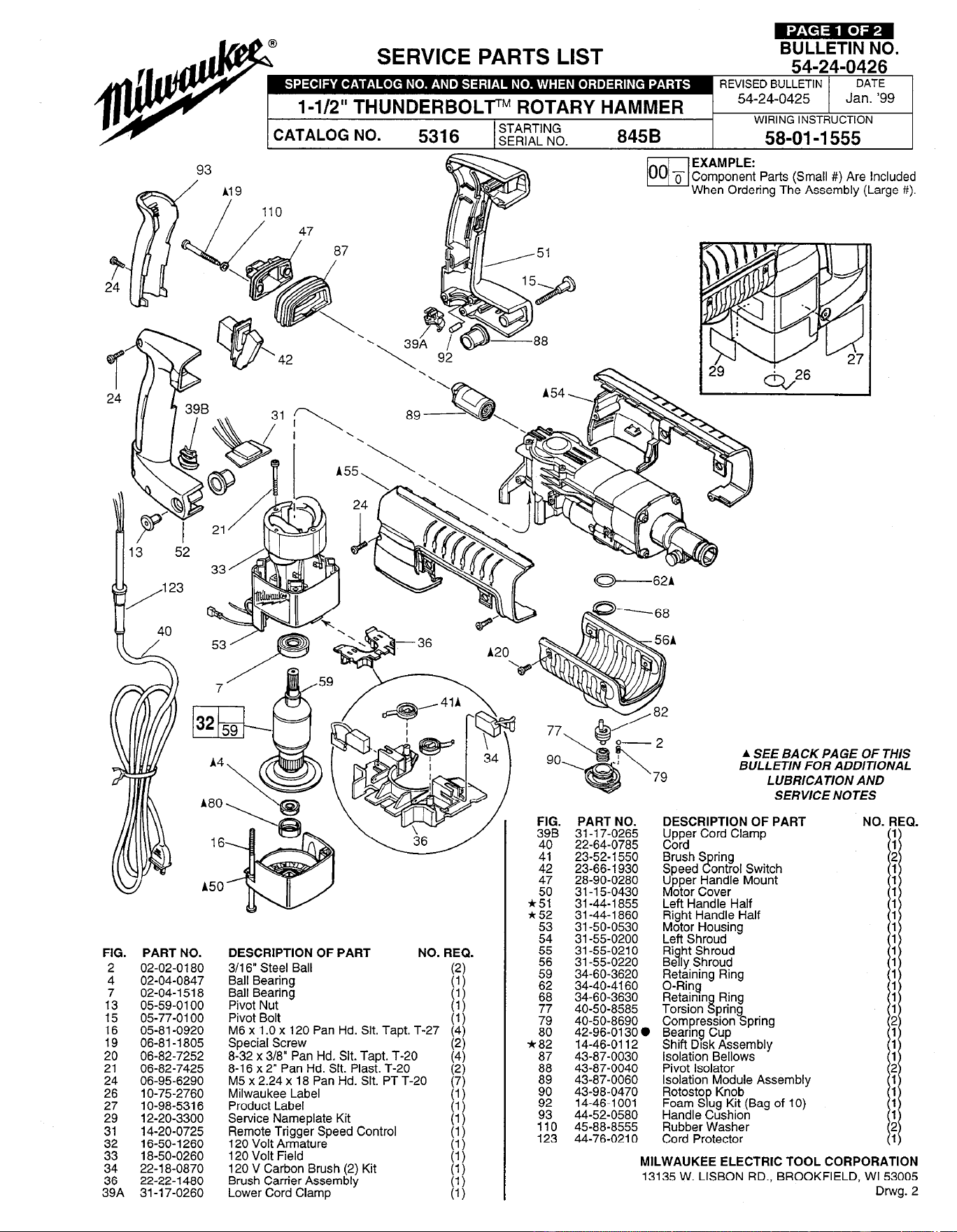
SERVICE PARTS LIST
FIG.
PART NO.
2 02-02-0180 02-04-0847
173 05-59-0100 02-04-l 518
15 05-77-0100
::
05-81-0920
06-81-l 805
20 06-82-7252
z
06-82-7425
06-95-6290
26 1 o-75-2760
27
1 O-98-531 6
::
12-20-3300
14-20-0725
:z
16-50-l 260
18-50-0260
z:
22-l 8-0870
22-22-1480
39A 31-l 7-0260
DESCRIPTION OF PART
NO. REQ.
3/l 6” Steel Ball
Ball Bearing
1:)
Ball Bearing
Pivot Nut [I{
Pivot Bolt
(1)
M6 x 1 .O x 120 Pan Hd. Slt. Tapt. T-27
(4)
Special Screw
(2)
8-32 x 3/8” Pan Hd. Slt. Tapt. T-20
8-l 6 x 2” Pan Hd. Slt. Plast. T-20
I;;
M5 x 2.24 x 18 Pan Hd. Slt. PT T-20
Milwaukee Label I:{
Product Label
(1)
Service Nameplate Kit
Remote Trigger Speed Control
I;{
120 Volt Armature
(1)
120 Volt Field
120 V Carbon Brush (2) Kit
I;{
Brush Carrier Assembly
Lower Cord Clamp
PART NO.
31-l 7-0265
22-64-0785
23-52-l 550
23-66-l 930
28-90-0280
31-l 5-0430
31-44-l 855
31-44-l 860
31-50-0530
31-55-0200
31-55-0210
31-55-0220
34-60-3620
34-40-4160
34-60-3630
40-50-8585
40-50-8690
42-96-0130 0
14-46-0112
43-87-0030
43-87-0040
43-87-0060
43-98-0470
14-46-1001
44-52-0580
45-88-8555
44-76-0210
54-24-0426
REVISED BULLETIN 1
DATE
54-24-0425
Jan. ‘99
WIRING INSTRUCTION
58-01-I 555
A SEE BACK PAGE OF THIS
BULLETIN FOR ADDITIONAL
LUBRICATION AND
SERVICE NOTES
DESCRIPTION OF PART
Upper Cord Clamp
Cord
Brush S
r!
ring
Speed ontrol Switch
Mp
U per Handle Mount
otor Cover
Left Handle Half
Right Handle Half
Motor Housing
Left Shroud
Ri
9
ht Shroud
Be ly Shroud
Retaining Ring
O-Ring
~%;~$Y~~pring
Beanng Cup
Shift Drsk Assembly
Isolation Bellows
Pivot Isolator
Isolation Module Assembly
~%%$$!!(Bag of 10)
Handle Cushion
Rubber Washer
Cord Protector
MILWAUKEE ELECTRIC TOOL CORPORATION
13135 W. LISBON RD., BROOKFIELD, WI 53005
Drwg. 2
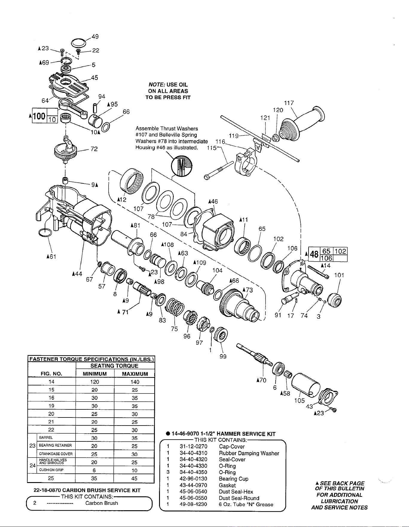
NOTE: USE OIL
ON ALL AREAS
TO BE PRESS FIT
Assemble Thrust Washers
6
FASTENER TORQUE SPECIFICATIONS IINJLBS.
SEATING TORQUE
FIG. NO.
1 MINIMUM 1 MAXIMUM
14
120
140
15 20
25
16
30 35
22-18-0870 CARBON BRUSH SERVICE KIT
r---_-THIS K’T zz,“:sr]
0 14-46-9070 1 -l/2” HAMMER SERVICE KIT
THIS KIT CONTAINS:
1 31-l 2-0270 Cap-Cover
1 34-40-4310 Rubber Damping Washer
1 34-40-4320 Seal-Cover
1 34-40-4330 O-Ring
3 34-40-4350 O-Ring
1 42-96-0130 Bearing Cup
1 43-44-0970 Gasket
1 45-06-0540 Dust Seal-Hex
1 45-06-0550 Dust Seal-Round
1 49-08-4230 6 Oz. Tube “N” Grease
ASEEBACKPAGE ‘.
OF THIS BULLETIN
FOR ADDITIONAL
LUBRICATION
AND SERVICE NOTES
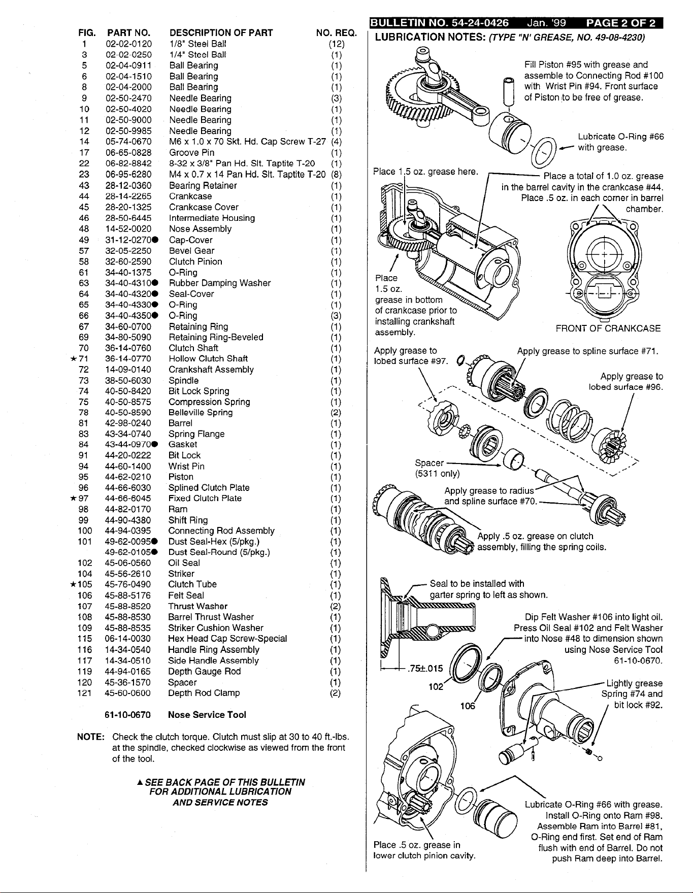
FIG.
3
5
6
8
9
10
11
12
14
17
22
23
43
44
45
46
48
49
57
58
61
63
64
65
66
67
69
70
*71
72
73
74
75
78
81
83
84
91
94
95
96
*97
98
99
100
101
102
104
*105
106
107
108
109
115
116
117
119
120
121
PART NO.
02-02-0120
02-02-0250
02-04-0911
02-04-l 5 10
02-04-2000
02-50-2470
02-50-4020
02-50-9000
02-50-9985
05-74-0670
06-65-0828
06-82-8842
06-95-6280
28-l 2-0360
28-14-2265
28-20-1325
28-50-6445
14-52-0020
31-12-0270.
32-05-2250
32-60-2590
34-40-l 375
34-40-4310.
34-40-4320@
34-40-4330a
34-40-4350a
34-60-0700
34-80-5090
36-14-0760
36-14-0770
14-09-0140
38-50-6030
40-50-8420
40-50-8575
40-50-8590
42-98-0240
43-34-0740
43-44-0970.
44-20-0222
44-60-1400
44-62-0210
44-66-6030
44-66-6045
44-82-0170
44-90-4380
44-94-0395
49-62-0095.
49-62-0105.
45-06-0560
45-56-2610
45-76-0490
45-88-5176
45-88-8520
45-88-8530
45-88-8535
06-l 4-0030
14-34-0540
14-34-0510
44-94-0165
45-36-l 570
45-60-0600
61-10-0670
Nose Service Tool
DESCRIPTION OF PART NO. REQ.
l/8” Steel Ball
(12)
l/4” Steel Bait
(1)
Ball Bearing
(1)
Ball Bearing
(1)
Ball Bearing
(1)
Needle Bearing
(3)
Needle Bearing
(1)
Needle Bearing
(1)
Needle Bearing
(1)
M6 x 1 .O x 70 Skt. Hd. Cap Screw T-27 (4)
Groove Pin
(1)
8-32 x 3/8” Pan Hd. Slt. Taptite T-20
(1)
M4 x 0.7 x 14 Pan Hd. Slt. Taotite T-20 (8)
Bearing Retainer
(1)
Crankcase
(1)
Crankcase Cover
(1)
Intermediate Housing
(1)
Nose Assembly
(1)
Cap-Cover
(1)
Bevel Gear
(1)
Clutch Pinion
(1)
O-Ring
(1)
Rubber Damping Washer
(1)
Seal-Cover
(1)
O-Ring
(1)
O-Ring
(3)
Retaining Ring
(1)
Retaining Ring-Beveled
(1)
Clutch Shaft
(1)
Hollow Clutch Shaft
(1)
Crankshaft Assembly
(1)
Spindle
(1)
Bit Lock Spring
(1)
Compression Spring
(1)
Belleville Spring
(2)
Barrel
(1)
Spring Flange
(1)
Gasket
(1)
Bit Lock
(1)
Wrist Pin
(1)
Piston
(1)
Splined Clutch Plate
(1)
Fixed Clutch Plate
(1)
Ram
(1)
Shift Ring
(1)
Connecting Rod Assembly
(1)
Dust Seal-Hex (5/pkg.)
(1)
Dust Seal-Round (5/pkg.)
(1)
Oil Seal
(1)
Striker
(1)
Clutch Tube
(1)
Felt Seal
(1)
Thrust Washer
(2)
Barrel Thrust Washer
(1)
Striker Cushion Washer
(1)
Hex Head Cap Screw-Special
(1)
Handle Ring Assembly
(1)
Side Handle Assembly
(1)
Depth Gauge Rod
(1)
Spacer
(1)
Depth Rod Clamp
(2)
NOTE: Check the clutch torque. Clutch must slip at 30 to 40 ft.-lbs.
at the spindle, checked clockwise as viewed from the front
of the tool.
A SEE BACK PAGE OF THIS BULLETIN
FOR ADDITIONAL LUBRICATION
AND SERVICE NOTES
LUBRICATION NOTES: (TYPE “N’ GREASE, NO. 49-08-4230)
Fill Piston #95 with grease and
assemble to Connecting Rod #lOO
with Wrist Pin #94. Front surface
of Piston ito be free of grease.
Lubricate O-Ring #66
Place a total of 1 .O oz. grease
el cavity in the crankcase #44.
ace .5 oz. in each corner in barrel
ply grease to spline surface #71.
Apply grease to
lobed surface #96.
5 oz. grease on clut
to left as shown.
Dip Felt Washer #106 into light oil.
ess Oil Seal #102 and Felt Washer
into Nose #48 to dimension shown
using Nose Service Tool
61-l o-0670.
Place .5 oz. grease in
lower clutch pinion cavity.
ate O-Ring #66 with grease.
nstall O-Ring onto Ram #98.
O-Ring end first. Set end of Ram
flush with end of Barrel. Do not
push Ram deep into Barrel.
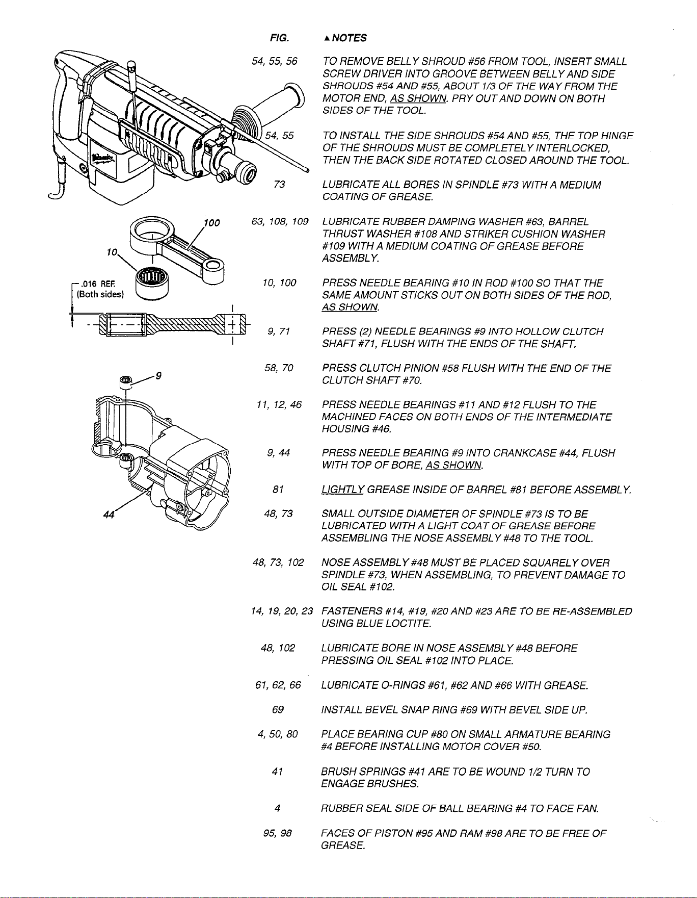
FIG.
A NOTES
54, 55, 56 TO REMOVE BELLY SHROUD #56 FROM TOOL, INSERT SMALL
SCREW DRIVER INTO GROOVE BETWEEN BELLY AND SIDE
SHROUDS #54 AND #55, ABOUT l/3 OF THE WAY FROM THE
MOTOR END, AS SHOWN. PRY OUTAND DOWN ON BOTH
SIDES OF THE TOOL.
63, 108, 109
10, 100
9, 71
/g
58, 70
e
11, 12, 46
PRESS NEEDLE BEARINGS #I 1 AND #12 FLUSH TO THE
MACHINED FACES ON BOTH ENDS OF THE INTERMEDIATE
HOUSING #46.
9, 44
PRESS NEEDLE BEARING #9 INTO CRANKCASE #44, FLUSH
WITH TOP OF BORE, AS SHOWN.
81 LIGHTLY GREASE INSIDE OF BARREL #81 BEFORE ASSEMBLY.
48, 73 SMALL OUTSIDE DIAMETER OF SPINDLE #73 IS TO BE
LUBRICATED WITH A LIGHT COAT OF GREASE BEFORE
ASSEMBLING THE NOSE ASSEMBL Y #48 TO THE TOOL.
48, 73, 102
14, 19, 20, 23
48, 102
61, 62, 66
69
4, 50, 80
41
4 RUBBER SEAL SIDE OF BALL BEARING #4 TO FACE FAN.
95, 98
FACES OF PISTON #95 AND RAM #98 ARE TO BE FREE OF
GREASE.
TO INSTALL THE SIDE SHROUDS #54 AND #55, THE TOP HINGE
OF THE SHROUDS MUST BE COMPLETELY INTERLOCKED,
THEN THE BACK SIDE ROTATED CLOSED AROUND THE TOOL.
LUBRICATE ALL BORES IN SPINDLE #73 WITH A MEDIUM
COATING OF GREASE.
LUBRICATE RUBBER DAMPING WASHER #63, BARREL
THRUST WASHER #108 AND STRIKER CUSHION WASHER
#109 WITH A MEDIUM COATING OF GREASE BEFORE
ASSEMBLY.
PRESS NEEDLE BEARING #10 IN ROD #100 SO THAT THE
SAME AMOUNT STICKS OUT ON BOTH SIDES OF THE ROD,
AS SHOWN.
PRESS (2) NEEDLE BEARINGS #9 INTO HOLLOW CLUTCH
SHAFT #71, FLUSH WITH THE ENDS OF THE SHAFT.
PRESS CLUTCH PINION #58 FLUSH WITH THE END OF THE
CLUTCH SHAFT #70.
NOSE ASSEMBLY #48 MUST BE PLACED SQUARELY OVER
SPINDLE #73, WHEN ASSEMBLING, TO PREVENT DAMAGE TO
OIL SEAL #102.
FASTENERS #14, #19, #20 AND #23 ARE TO BE RE-ASSEMBLED
USING BLUE LOCTITE.
LUBRICATE BORE IN NOSE ASSEMBL Y #48 BEFORE
PRESSING OIL SEAL #102 INTO PLACE.
LUBRICATE O-RINGS #61, #62 AND #66 WITH GREASE.
INSTALL BEVEL SNAP RING #69 WITH BEVEL SIDE UP.
PLACE BEARING CUP #80 ON SMALL ARMATURE BEARING
#4 BEFORE INSTALLING MOTOR COVER #50.
BRUSH SPRINGS #41 ARE TO BE WOUND l/2 TURN TO
ENGAGE BRUSHES.