
MILWAUKEE ELECTRIC TOOL CORPORATION
13135 W. Lisbon Road, Brookeld, WI 53005
Drwg. 2
BULLETIN NO.
54-24-0076
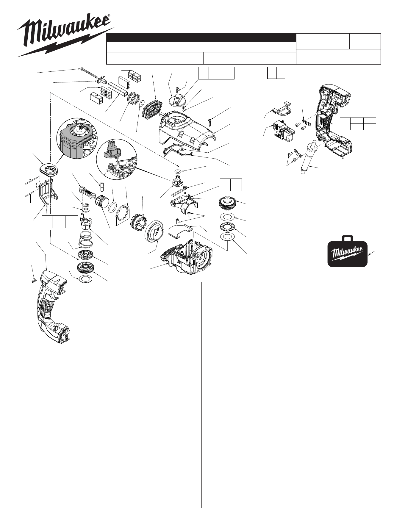
SERVICE PARTS LIST
CATALOG NO. 5268-21
REVISED BULLETIN
SPECIFY CATALOG NO. AND SERIAL NO. WHEN ORDERING PARTS
1-1/8" (3Kg) SDS Rotary Hammer
STARTING
SERIAL NO.
DATE
Feb. 2019
WIRING INSTRUCTION
F82B or F82C
EXAMPLE:
Component Parts (Small #) Are Included
When Ordering The Assembly (Large #).
0
00
SEE PAGE 5
54-24-0075
FIG. PART NO. DESCRIPTION OF PART NO. REQ.
9b 06-75-2408 M4 x 17mm Pan Hd. Taptite T-20 w/Nylok 6
14b 34-40-0068 O-Ring (1 on Piston #42b, 1 on Ram #14a) 2
18 14-29-0067 Gearbox Assembly 1
23a 05-78-0105 M4 x 10mm Pan Hd. Taptite Screw 2
26c 06-82-2025 M3.5 x 16mm Pan Hd. Plastite T-10 Screw 1
26d 05-88-1610 M3.5 x 10mm Pan Hd. Plastite T-10 Screw 7
34 45-88-0106 Washer 1
35 32-60-0042 Crank Gear Assembly with Needle Bearing 1
36 44-90-0152 Crank Shift Ring 1
37 40-50-0107 Crank Spring 1
38 14-09-0110 Crank Assembly 1
39 44-66-0122 Crank Shim 1
40 42-70-5268 Retaining E-Ring 1
41 14-46-0117 Chisel Shifter Assembly 1
41a --------------- M2 x 27mm Dowel Pin 1
41b --------------- M2 x 40mm Dowel Pin 1
41c --------------- Chisel Bracket 1
41d --------------- Chisel Shift Driver 1
42a 44-94-0022 Connecting Rod 1
42b 44-62-0302 Piston 1
42c 44-60-0147 Wrist Pin 1
43 44-66-0303 Locking Plate 1
44 44-90-0127 Shift Ring 1
45 32-05-0202 Bevel Gear 1
46 45-88-0112 Thrust Washer 2
FIG. PART NO. DESCRIPTION OF PART NO. REQ.
47 02-50-0105 Thrust Bearing 1
48 32-10-0094 Clutch Gear Assembly 1
49 44-66-0132 Clamp Plate 1
50 14-46-0037 Fork Assembly 1
50a --------------- Fork 1
50b --------------- Fork Spring 1
51 42-90-0022 Shifting Coupler 1
52 34-40-0093 O-Ring 1
53 42-92-0053 Gearcase Gasket (See page three) 1
54 28-20-0183 Gearcase Cover 1
55 44-10-0057 Selector Knob Assembly 1
55a --------------- Selector Ball 1
55b --------------- Selector Spring 1
55c --------------- Selector Knob 1
56 22-90-0132 Top Grommet 1
57 45-88-0152 Vibration Washer
(1 each for top & bottom AVS)
2
58 44-20-0141 Top AVS Square Guide Pipe 1
59 40-50-0211 Top AVS Spring 1
60 42-38-0077 Vibration Bumper
(2 each for top & bottom AVS)
4
61 42-38-0137 Bumper Holder
(2 each for top & bottom AVS)
4
62a 42-36-0032 Retaining Plate
(Top AVS)
1
63 05-78-0012 M4 x 52mm Scr.
(1 each for top & bottom AVS)
2
64 42-42-0053 Forward/Reverse Button 1
65 23-66-0027 On-O Switch 1
66 14-34-0107 Handle Assembly 1
66a --------------- Left Handle Halve 1
66b --------------- Right Handle Halve 1
68 42-68-0601 Power Cord Clamp 2
69 05-78-5313 M4 x 9.5mm Pan Hd. Plastite T-15 Screw 4
70 22-64-0032 120V Power Cord Assembly 1
80 42-55-5268 Blow Molded Carrying Case 1
83 45-88-0014 Rubber Washer 2
l
l
l
l
l= Component of Rotary Hammer
Service Kit No. 14-46-5268
(See page three)
80
80
45
18
48
46
47
46
52
50b
50a
23a
49
44
43
14b
41d
41b
41a
41c
66b
26d
(7x)
40
39
37
42b
38
36
35
63
62a
61(2x)
58
59
57
60(2x)
56
55c
26c
55b
55a
9b(6x)
54
51
68
(2x)
69
(4x)
70 66a
64
65
34
26d 66a
66b
66
41a 41b
41c 41d
41
55a 55b
55c
55
50a
50b
50
42a 42c
83(2x)
See note below
53 See page 3
*NOTE:
There are two Rubber Washers (83)
that are to be installed in recessed
pockets on the bottom of the Gearcase
Cover (54). The washers are held in
place by the two middle Gearcase
Screws (9b).
«
«
«= Part number change from
previous service parts list.
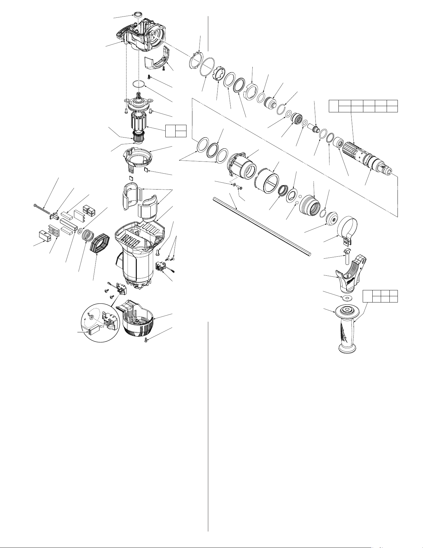
FIG. PART NO. DESCRIPTION NO. REQ.
19 31-15-0039 Shroud 1
20 05-86-1000 M3 x 9.5mm Pan Hd. Tapt. T-10 Scr. 2
21 34-40-5320 O-Ring 1
22 14-50-0052 120V Armature Assembly 1
22a 02-04-5382 Ball Bearing 1
22b 23-16-0092 Commutator Insulator Disc 1
23b 05-78-0105 M4 x 10mm Pan Hd. Taptite Screw 2
24 31-05-0057 Bae 1
25 42-28-0085 Field Isolation Block 2
26a 05-88-1610 M3.5 x 10mm Pan Hd. Plastite T-10 Screw 3
27 23-44-0063 Motor Housing/Brush Cover 1
28 06-82-0062 M3 x 8mm Pan Hd. Washer T-10 Screw 4
29 22-20-0019 120V Carbon Brush Assembly 2
29a 22-18-5268 120V Carbon Brush (Set of 2) 1
30 05-74-0990 M5 x 15mm Pan Hd. Taptite T-25 Screw 4
31 28-50-0107 Motor Housing Assembly 1
33 18-07-0097 120V Split Field 1
57 45-88-0152 Vibration Washer 2
60 42-38-0077 Vibration Bumper 4
61 42-38-0137 Bumper Holder 4
62b 44-66-0131 Retaining Plate
(Bottom AVS)
1
63 05-78-0012 M4 x 52mm Scr.
(1 each for top & bottom AVS)
2
74 44-52-0052 Foam Block 2
75 40-50-0138 Bottom AVS Spring 1
76 44-68-0155 Bottom AVS Square Guide Pipe 1
77 22-90-0152 Bottom Grommet 1
78 12-20-5268 Service Nameplate (Not Shown) 1
81 45-88-0042 Bumper/Washer Holder 1
82 05-90-0225 Lock Washer 4
90 45-06-0042 Motor Seal 1
7h
14b
14a
13j
19
20
21
23b
24
11
25
33
31
30(4x)
28(4x)
29(2x)
27
26a
(3x)
18
13h
13g
13f
13e
13d
13c
13b
13a
12
10
8
9a
(4x)
6
5
4
(2x)
3
2
1
7a
7b
7c
7f
7g
77
75
57
76
61
(2x)
60
(2x)
74(2x)
62b
63
29a(2x)
22b
22a
7a 7b 7c
7f 7g 7h
7
13a 13b 13c 13d 13e
13f 13g 13h 13j
13
22a
22b
22
12
11
15
16
17
81
82
(4x)
90
FIG. PART NO. DESCRIPTION OF PART NO. REQ.
1 45-12-0045 Dust Shield 1
2 44-90-5262 Retaining Ring 1
3 45-22-0062 Collar with Steel Insert 1
4 02-02-0275 7mm Steel Ball 2
5 42-36-0017 Ball Support Plate 1
6 40-50-0082 Conical Spring 1
7 14-34-0015 Side Handle Assembly 1
7a 44-66-0072 Clamp Collar 1
7b 05-81-5376 M8 x 53mm Screw 1
7c --------------- Side Handle Carrier Assembly 1
7f 45-88-5377 Washer 1
7g 31-05-5383 Side Handle 1
7h 44-94-5381 Depth Rod 1
8 45-22-0045 Side Handle Sleeve 1
9a 05-78-5316 M4 x 14mm Pan Hd. Taptite T-20 Screw 4
10 42-40-0027 Bushing Sleeve Assembly with Seals 1
11 45-88-0157 Washer 3
12 42-38-0127 Bumper 2
13 14-46-0197 Spindle Assembly 1
13a 38-50-0052 Spindle 1
13b 43-06-0060 Brake Ring 1
13c 44-66-0203 Anvil Ring 1
13d 34-40-0032 Square O-Ring 1
13e 42-06-0027 Anvil/Striker 1
13f 34-40-0052 Anvil O-Ring 1
13g 42-06-0067 Ram Catcher 1
13h 44-90-0032 Back Pressure Ring 1
13j 34-60-0027 Anvil Retaining Ring 1
14a 45-56-0065 Ram 1
FIG. PART NO. DESCRIPTION OF PART NO. REQ.
14b 34-40-0068 O-Ring (1 on Ram #14a, 1 on Piston #42b) 2
15 42-76-0037 Spindle Collar 1
16 34-40-0082 O-Ring 1
17 44-60-0119 Retaining Plate 1
18 14-29-0067 Gearbox Assembly 1
l
l
l
l
l
l
l
l
l
l= Component of Rotary Hammer
Service Kit No. 14-46-5268
l
l
l
l
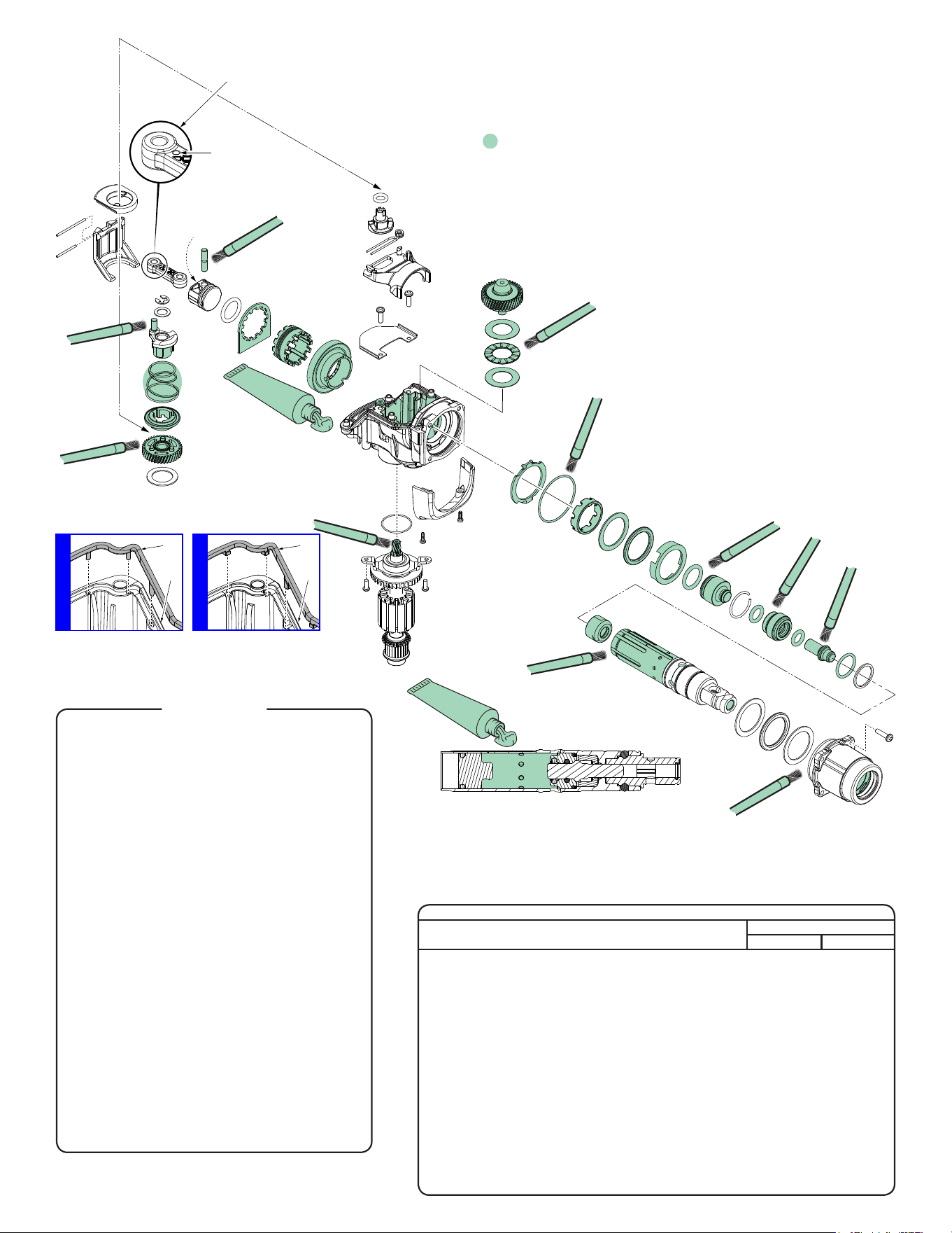
LUBRICATION NOTES:
Urethyn GE00 Grease
No. 49-08-5355, 2.8oz. / 80g tube
A total of approx. 60 grams will be used. Prior to reinstalling, clean gear
assemblies with a clean, dry cloth. Lightly coat all parts highlighted here
with Urethyn GE00 grease. Apply a greater amount of grease to all
internal and external gear teeth.
Coat pin of
crank assy.
Coat entire
crank gear
assembly with grease.
Be sure to place a liberal
amount on the gear teeth.
Coat the
inside walls
of gearbox and the
crank gear pin with
grease. Place approxi-
mately 40 grams of grease
in the cavity after the
gearing is installed.
Place a heavy coat
of grease on rotor
pinion
Coat
wrist pin
Coat entire clutch gear assembly
with grease. Be sure to place a
liberal amount on the gear teeth.
Brush both sides of thrust washers
and thrust bearing with grease.
Coat o-ring
Fill back of piston with grease.
There is to be no grease
on face of
piston.
Coat o-rings, ram and striker
with grease. Brush the exterior
and inside of the ram catcher.
NOTE: No grease on the rear
face of ram.
Place approximately
2 grams of grease in the
rear inside cavity of spindle.
Lightly coat outside barrel as shown.
Prior to installing spindle
assembly, place a heavy
coating of grease in the
interior cavity of bushing/
sleeve assembly.
IMPORTANT:
Dimpled end of connecting
rod to crank assembly.
Dimple
Prior to installing the Ram Assembly place
18 grams of grease inside of spindle barrel
behind the ram catcher.
1 42-12-0045 Dust Shield (1)
2 44-90-5262 Retaining Ring (1)
4 02-02-0275 7mm Steel Ball (2)
5 42-36-0017 Ball Support Plate (1)
12 42-38-0127 Bumper (2)
13d 34-40-0032 Square O-Ring (1)
13f 34-40-0052 Anvil O-Ring (1)
13h 44-90-0032 Back Pressure Ring (1)
13j 34-60-0027 Anvil Retaining Ring (1)
14b 34-40-0068 O-Ring (2)
16 34-40-0082 O-Ring (1)
21 34-40-5320 O-Ring (1)
29a 22-18-5268 120V Carbon Brush (Set of 2) (1)
For models 5268-21, 5268-59B.
29a 22-18-5269 230V Carbon Brush (Set of 2) (1)
For model 5268-50, 5268-59
and 5268-59A.
40 42-70-5268 Retaining E-Ring (1)
52 34-40-0093 O-Ring (1)
53 42-92-0052
Gearcase Gasket (See detail above)
(1)
53 42-92-0053
Gearcase Gasket (See detail above)
(1)
83 45-88-0014 Rubber Washer (2)
58-22-5268 Instruction Sheet (1)
49-08-5355 Urethyn GE00 Grease
60 grams required-
(80 gram, 2.8oz tube) (1)
l14-46-5268
Rotary Hammer Service Kit
(For 110/120V tools discard 230V Carbon Brush Set,
for 220/230V tools discard 120V Carbon Brush Set)
SCREW TORQUE SPECIFICATIONS
SEAT TORQUE
FIG. PART NO. WHERE USED (KG/CM) (IN/LBS)
9a 05-78-5316 Bushing Sleeve Assembly 26 22.5
9b 06-75-2408 Gearcase Cover (4) Rear and Middle 32 27.8
9b 06-75-2408 Gearcase Cover (2) Front 32 27.8
20 05-86-1000 Shroud 12 10.5
23a 05-78-0105 Clamp Plate 26 22.5
23b 05-78-0105 Rotor Bearing Plate 33 28.5
26a 05-88-1610 Motor Housing/Brush Cover 6.5 5.5
26c 06-82-2025 Selector Knob 8.5 7.5
26d 05-88-1610 Right Handle Halve 6.5 5.5
28 06-82-0062 Carbon Brush Assembly 5 4.5
30 05-74-0990 Motor Housing Assembly 33 28.5
63 05-78-0012 Retaining Plate (Top and Bottom) 20 17
69 05-78-5313 Cord Clamps (Power Cord) 14 12
69 05-78-5313 Cord Clamps (Glass Fiber Tube) 11 9.5
Switch Screws 5.5 4.5
NOTE: It is recommended to order Motor Seal #90
(45-06-0042) at the same time that Rotary Hammer
Service Kit No. 14-46-5268 is installed.
OLD DESIGN
53
54
NEW DESIGN
53
54
Bottom View of Gear Case Cover #54 with
Gasket #53- There are two gaskets in Service
Kit 14-46-5268. Visually inspect gear case cover
to determine which gasket to install. Discard the
other gasket.
1
61-10-0045
Seal Press Pin
#90
Motor Seal
61-10-0043
Push Sleeve
#2
Retaining Ring
61-10-0041
Ring Expander
Cone
2
#2
Retaining Ring
#3
Collar
#4
Steel Balls
#5
Ball Support
Plate
#6
Conical
Spring
1
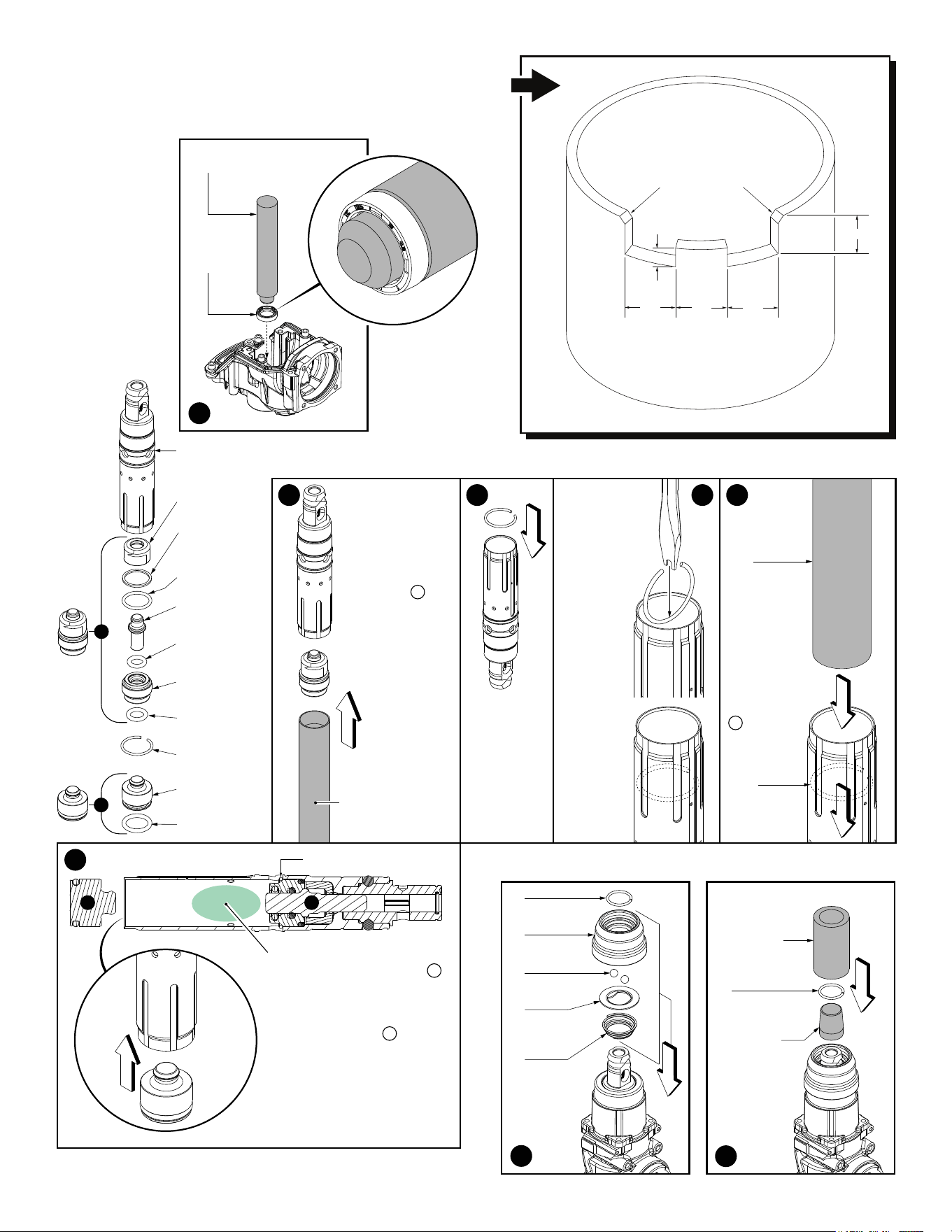
SERVICE TOOLS:
61-10-0041
Ring Expander
Cone
61-10-0043
Push Sleeve
61-10-0045
Seal Press Pin
61-10-0049
Anvil Sleeve
Snap Ring Bar
.75”
.75”
.75”
.75”
.375”
Cut or file a 45º
Chamfer here
NOTE: As an aid to working on the gearcase
and spindle assemblies, a bench top xture
can be made from a 3.25” piece of 4” PVC pipe.
The contour of the pipe can be cut according to
dimensions in the illustration.
1
4
5
Prior to placing the assembled
internal spindle components B
(Ram and O-Ring) into spindle
cavity, apply approximately 18
grams of Urethyn GE00 Grease
into the barrel behind internal
spindle components A .
Insert Ram/O-Ring Assembly
into barrel of spindle.
#13a
Spindle
#13b
Brake Ring
#13c
Anvil Ring
#13d
Square O-Ring
#13e
Anvil/Striker
#13f
Anvil O-Ring
#13g
Ram Catcher
#13h Back
Pressure Ring
#13j Anvil
Retaining Ring
#14a Ram
#14b Ram
O-Ring
Prior to installing
internal spindle
components, lightly
grease the inside
cavity of spindle.
Place the assembled
internal spindle
components A into
cavity end of service
tool 61-10-0049
(Anvil Sleeve Snap
Ring Bar).
Push components
into the spindle until
parts bottom out.
Use a rubber
mallet to the end
of the service
tool to assure
that the inside
components are
properly seated.
61-10-0049
Anvil Sleeve Snap
Ring Bar
A
B
2
3
Place Retaining
Ring #13j as
shown on the
spindle #13a.
As an aid, it
may be helpful
to file or grind
a notch on the
bottom flat
of a screw-
driver to
accomodate
the round
of the ring.
As force is
applied, the
open end of
the ring will
close in on
screwdriver.
Once deep
enough in
the cavity,
rotate ring
horizontally.
Secure the
parts inside
the Anvil with
Retaining
Ring #13j.
See figures 3
and 4 for an
installation aid.
61-10-0049
Anvil Sleeve
Snap Ring
Bar
Insert service
tool into rear
of spindle and
push down-
ward. Slide
retaining ring
into internal
slot to secure
internal spindle
components
A .
#13j Anvil
Retaining
Ring
B A
#13j Anvil Retaining Ring
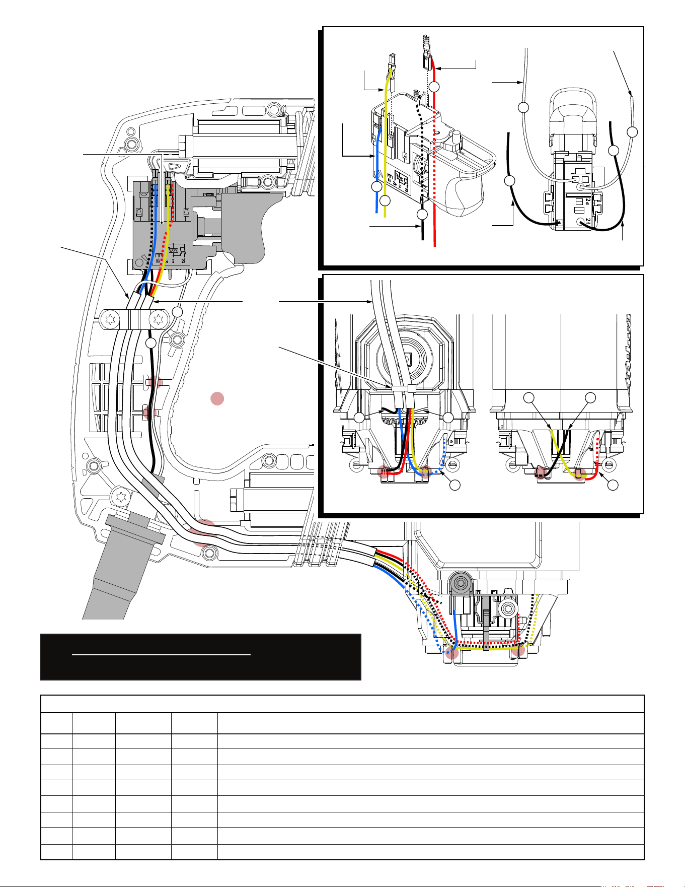
BLACK from cord
WHITE
from cord
BLACK
from the left
rear stator
RED
from the
left brush
WHITE
from the left
rear stator
BLACK
from the right
front stator
**
YELLOW
from the right
front stator
BLUE
from the
right
brush
**
Motor Housing
(Back View)
Motor Housing
(Front View)
Insulated
Sleeving
Wire Tie
= WIRE TRAPS
or GUIDES
Insulated
sleeving to
extend .25 min.
beyond clamp
area.
1
2
2
1
3
4
5
6
7
8
63
4
8
5
7
**
It is recommended that a .75” piece
of heat shrink tubing be used
to contain wires #3 & #4
at the right side of
the switch. Do the
same for wires
#5 & #6 on the
other side.
AS AN AID TO REASSEMBLY, TAKE NOTICE OF WIRE
ROUTING AND POSITION IN WIRE GUIDES AND TRAPS
WHILE DISMANTLING TOOL.
BE CAREFUL AND AVOID PINCHING WIRES BETWEEN
HANDLE HALVES WHEN ASSEMBLING.
1 White 22-64-0032 ----- Component of cord set. Connect to position 1â on bottom of switch as shown.
2 Black 22-64-0032 ----- Component of cord set. Connect to position 2â on bottom of switch as shown.
3 Blue 23-94-0072 ----- Blue Leadwire Assembly. Connect to position 7 on switch and left brush holder as shown.
4 Yellow 18-07-0097 ----- Component of split eld (front halve). Connect to position 6 on switch as shown.
5 Black** 18-07-0097 ----- Component of split eld (rear halve). Connect to position 5 on switch as shown.
6 Red 23-94-0062 ----- Red Leadwire Assembly. Connect to position 8 on switch and right brush holder as shown.
7 White 18-07-0097 ----- Component of split eld (rear halve). Connect to position 1 on the bottom of switch as shown.
8 Black 18-07-0097 ----- Component of split eld (front halve). Connect to position 2 on bottom of switch as shown.
Terminals, Connectors and 1 or 2 End Wire Preparation
Wire
Color
Origin or
Gauge
Wire
No.
Length
WIRING SPECIFICATIONS
** TO AVOID CONFUSION, PLEASE NOTE:
The insulation color for eld wire #5 is BLACK. Early production of the
eld used in the 5268-21 Hammer had green insulation on wire #5 or
used black heat shrink tubing over the green insulation.