

Quick Start Guide
2500 Series
MULTIMODE FILTER /
RESONATOR MODULE 1047
Legendary 2500 Series 12 dB State Variable Filter Module for Eurorack
V 2.0
2 MULTIMODE FILTER / RESONATOR MODULE 1047 Quick Start Guide 3
7. Verwenden Sie nur
spezizierte Wagen,
Ständer, Stative,
Halterungen oder Tische.
Achten Sie darauf, beim
Bewegen der Wagen-
Geräte-Kombination ein
Umkippen zu vermeiden.
8. Vermeiden Sie die Installation in beengten Räumen
wie Bücherregalen.
9. Nicht in der Nähe von oenen Flammenquellen
platzieren, wie brennende Kerzen.
10. Betriebstemperaturbereich von 5° bis 45°C
(41° bis 113°F).
HAFTUNGSAUSSCHLUSS
Music Tribe übernimmt keine Haftung für Verluste,
die Personen entstanden sind, die sich ganz oder
teilweise auf hier enthaltene Beschreibungen,
Fotos oder Aussagen verlassen haben. Technische Daten,
Erscheinungsbild und andere Informationen können
ohne vorherige Ankündigung geändert werden. Alle
Warenzeichen sind Eigentum der jeweiligen Inhaber.
Midas, Klark Teknik, Lab Gruppen, Lake, Tannoy,
Turbosound, TC Electronic, TC Helicon, Behringer, Bugera,
Aston Microphones und Coolaudio sind Warenzeichen
oder eingetragene Warenzeichen der Music Tribe Global
Brands Ltd. © Music Tribe Global Brands Ltd. 2024 Alle
Rechte vorbehalten.
BESCHRÄNKTE GARANTIE
Die geltenden Garantiebedingungen und zusätzliche
Informationen bezüglich der von Music Tribe gewährten
beschränkten Garantie nden Sie online unter
community.musictribe.com/support.
(PT) Instruções de Seguranç
Importantes
1. Por favor, leia e siga todas as instruções.
2. Mantenha o aparelho longe da água, exceto para
produtos destinados ao uso externo.
3. Limpe apenas com um pano seco.
4. Não bloqueie nenhuma abertura de ventilação. Instale
de acordo com as instruções do fabricante.
5. Não instale próximo a fontes de calor, como
radiadores, grelhas de calor, fogões ou outros aparelhos
(incluindo amplicadores) que gerem calor.
6. Use apenas acessórios especicados pelo fabricante.
7. Use apenas carrinhos,
suportes, tripés, suportes
ou mesas especicados.
Tenha cuidado para evitar
tombamentos ao mover a
combinação carrinho/
aparelho.
8. Evite instalar em espaços connados, como estantes.
9. Não coloque perto de fontes de chama nua,
como velas acesas.
10. Intervalo de temperatura de operação de 5° a 45°C
(41° a 113° F).
LEGAL RENUNCIANTE
O Music Tribe não se responsabiliza por perda
alguma que possa ser sofrida por qualquer pessoa
que dependa, seja de maneira completa ou parcial,
de qualquer descrição, fotograa, ou declaração
aqui contidas. Dados técnicos, aparências e outras
informações estão sujeitas a modicações sem aviso
prévio. Todas as marcas são propriedade de seus
respectivos donos. Midas, Klark Teknik, Lab Gruppen,
Lake, Tannoy, Turbosound, TC Electronic, TC Helicon,
Behringer, Bugera, Aston Microphones e Coolaudio
são marcas ou marcas registradas do Music Tribe
Global Brands Ltd. © Music Tribe Global Brands Ltd.
2024 Todos direitos reservados.
GARANTIA LIMITADA
Para obter os termos de garantia aplicáveis e condições e
informações adicionais a respeito da garantia limitada do
Music Tribe, favor vericar detalhes na íntegra através do
website community.musictribe.com/support.
(IT) Istruzioni di sicurezza importanti
1. Per favore, leggere e seguire tutte le istruzioni.
2. Mantenere l'apparecchio lontano dall'acqua, tranne
per i prodotti destinati all'uso all'aperto.
3. Pulire solo con un panno asciutto.
4. Non ostruire alcuna apertura di ventilazione. Installare
in conformità alle istruzioni del produttore.
5. Non installare vicino a fonti di calore come
termosifoni, bocchette di calore, fornelli o altri apparecchi
(compresi gli amplicatori) che producono calore.
6. Utilizzare solo accessori specicati dal produttore.
7. Usare solo carrelli,
supporti, treppiedi, stae
o tavoli specicati. Prestare
attenzione per evitare il
ribaltamento durante lo
spostamento della
combinazione carrello/
apparecchio.
8. Evitare l'installazione in spazi connati come librerie.
9. Non posizionare vicino a fonti di amma nude,
come candele accese.
10. Intervallo di temperatura di funzionamento da
5° a 45°C (41° a 113°F).
DISCLAIMER LEGALE
Music Tribe non si assume alcuna responsabilità per
eventuali danni che possono essere subiti da chiunque
si adi in tutto o in parte a qualsiasi descrizione,
fotograa o dichiarazione contenuta qui. Speciche
tecniche, aspetti e altre informazioni sono soggette
a modiche senza preavviso. Tutti i marchi sono di
proprietà dei rispettivi titolari. Midas, Klark Teknik,
Lab Gruppen, Lake, Tannoy, Turbosound, TC Electronic,
TC Helicon, Behringer, Bugera, Aston Microphones e
Coolaudio sono marchi o marchi registrati di Music Tribe
Global Brands Ltd. © Music Tribe Global Brands Ltd.
2024 Tutti i diritti riservati.
GARANZIA LIMITATA
Per i termini e le condizioni di garanzia applicabili e le
informazioni aggiuntive relative alla garanzia limitata
di Music Tribe, consultare online i dettagli completi su
community.musictribe.com/support.
(NL) Belangrijke
veiligheidsvoorschriften
1. Lees alsjeblieft alle instructies en volg deze op.
2. Houd het apparaat uit de buurt van water, behalve
voor producten die bedoeld zijn voor buitengebruik.
3. Reinig alleen met een droge doek.
4. Blokker geen ventilatieopeningen. Installeer volgens
de instructies van de fabrikant.
5. Installeer niet in de buurt van warmtebronnen
zoals radiatoren, warmte registers, fornuizen of andere
apparaten (inclusief versterkers) die warmte produceren.
6. Gebruik alleen accessoires die door de fabrikant
zijn gespeciceerd.
7. Gebruik alleen
gespeciceerde karren,
standaards, statieven,
beugels of tafels. Wees
voorzichtig om kantelen te
voorkomen bij het
verplaatsen van de kar/
apparaatcombinatie.
8. Vermijd installatie in afgesloten ruimtes
zoals boekenkasten.
9. Plaats niet in de buurt van naakte vlambronnen,
zoals brandende kaarsen.
10. Bedrijfstemperatuurbereik
van 5° tot 45°C (41° tot 113°F).
WETTELIJKE ONTKENNING
Music Tribe aanvaardt geen aansprakelijkheid voor enig
verlies dat kan worden geleden door een persoon die
geheel of gedeeltelijk vertrouwt op enige beschrijving,
foto of verklaring hierin. Technische specicaties,
verschijningen en andere informatie kunnen zonder
voorafgaande kennisgeving worden gewijzigd. Alle
handelsmerken zijn eigendom van hun respectievelijke
eigenaren. Midas, Klark Teknik, Lab Gruppen, Lake,
Tannoy, Turbosound, TC Electronic, TC Helicon,
Behringer, Bugera, Aston Microphones en Coolaudio
(EN) Safety Instruction
1. Please read and follow all instructions.
2. Keep the apparatus away from water, except for
outdoor products.
3. Clean only with a dry cloth.
4. Do not block any ventilation openings. Install in
accordance with the manufacturer’s instructions.
5. Do not install near any heat sources such as radiators,
heat registers, stoves or other apparatus (including
ampliers) that produce heat.
6. Use only attachments/accessories specied by
the manufacturer.
7. Use only specied
carts, stands, tripods,
brackets, or tables. Use
caution to prevent tip-over
when moving the cart/
apparatus combination.
8. Avoid installing in conned spaces like bookcases.
9. Do not place near naked ame sources, such as
lighted candles.
10. Operating temperature range 5° to 45°C
(41° to 113°F).
LEGAL DISCLAIMER
Music Tribe accepts no liability for any loss which may
be suered by any person who relies either wholly or in
part upon any description, photograph, or statement
contained herein. Technical specications, appearances
and other information are subject to change without
notice. All trademarks are the property of their
respective owners. Midas, Klark Teknik, Lab Gruppen,
Lake, Tannoy, Turbosound, TC Electronic, TC Helicon,
Behringer, Bugera, Aston Microphones and Coolaudio
are trademarks or registered trademarks of Music
Tribe Global Brands Ltd. © Music Tribe Global Brands
Ltd. 2024 All rights reserved.
LIMITED WARRANTY
For the applicable warranty terms and conditions
and additional information regarding Music Tribe’s
Limited Warranty, please see complete details online at
community.musictribe.com/support.
(ES) Instrucción de seguridad
1. Por favor, lea y siga todas las instrucciones.
2. Mantenga el aparato alejado del agua, excepto para
productos destinados al uso en exteriores.
3. Limpie solo con un paño seco.
4. No bloquee ninguna abertura de ventilación. Instale
de acuerdo con las instrucciones del fabricante.
5. No instale cerca de fuentes de calor como radiadores,
registros de calor, estufas u otros aparatos (incluyendo
amplicadores) que generen calor.
6. Utilice solo accesorios especicados por el fabricante.
7. Use solo carros,
soportes, trípodes,
soportes o mesas
especicados. Tenga
precaución para evitar el
vuelco al mover la
combinación carro/
aparato.
8. Evite la instalación en espacios connados
como estanterías.
9. No colocar cerca de fuentes de llama desnuda,
como velas encendidas.
10. Rango de temperatura de funcionamiento de
5° a 45°C (41° a 113° F).
NEGACIÓN LEGAL
Music Tribe no admite ningún tipo de responsabilidad
por cualquier daño o pérdida que pudiera sufrir
cualquier persona por conar total o parcialmente en la
descripciones, fotografías o armaciones contenidas en
este documento. Las especicaciones técnicas, imágenes
y otras informaciones contenidas en este documento
están sujetas a modicaciones sin previo aviso. Todas las
marcas comerciales que aparecen aquí son propiedad
de sus respectivos dueños. Midas, Klark Teknik,
Lab Gruppen, Lake, Tannoy, Turbosound, TC Electronic,
TC Helicon, Behringer, Bugera, Aston Microphones y
Coolaudio son marcas comerciales o marcas registradas
de Music Tribe Global Brands Ltd. © Music Tribe Global
Brands Ltd. 2024 Reservados todos los derechos.
GARANTÍA LIMITADA
Si quiere conocer los detalles y condiciones aplicables
de la garantía así como información adicional sobre
la Garantía limitada de Music Tribe, consulte online
toda la información en la web community.musictribe.
com/support.
(FR) Consignes de sécurité
1. Veuillez lire et suivre toutes les instructions.
2. Gardez l'appareil éloigné de l'eau, sauf pour les
produits destinés à une utilisation en extérieur.
3. Nettoyez uniquement avec un chion sec.
4. Ne bloquez aucune ouverture de ventilation. Installez
conformément aux instructions du fabricant.
5. N'installez pas près de sources de chaleur telles
que radiateurs, grilles de chaleur, cuisinières ou autres
appareils (y compris les amplicateurs) qui produisent de
la chaleur.
6. Utilisez uniquement les accessoires spéciés par
le fabricant.
7. Utilisez uniquement
des chariots, des supports,
des trépieds, des supports
ou des tables spéciés.
Faites attention pour éviter
le renversement lors du
déplacement de la
combinaison chariot/
appareil.
8. Évitez l'installation dans des espaces connés comme
les bibliothèques.
9. Ne pas placer près de sources de amme nue,
telles que des bougies allumées.
10. Plage de température de fonctionnement de
5° à 45°C (41° à 113°F)
DÉNI LÉGAL
Music Tribe ne peut être tenu pour responsable pour
toute perte pouvant être subie par toute personne
se ant en partie ou en totalité à toute description,
photographie ou armation contenue dans ce
document. Les caractéristiques, l’apparence et d’autres
informations peuvent faire l’objet de modications
sans notication. Toutes les marques appartiennent
à leurs propriétaires respectifs. Midas, Klark Teknik,
Lab Gruppen, Lake, Tannoy, Turbosound, TC Electronic,
TC Helicon, Behringer, Bugera, Aston Microphones et
Coolaudio sont des marques ou marques déposées de
Music Tribe Global Brands Ltd. © Music Tribe Global
Brands Ltd. 2024 Tous droits réservés.
GARANTIE LIMITÉE
Pour connaître les termes et conditions de
garantie applicables, ainsi que les informations
supplémentaires et détaillées sur la Garantie
Limitée de Music Tribe, consultez le site Internet
community.musictribe.com/support.
(DE) Wichtige Sicherheitshinweise
1. Bitte lesen Sie alle Anweisungen sorgfältig durch und
befolgen Sie diese.
2. Halten Sie das Gerät von Wasser fern, außer für
Produkte, die für den Außeneinsatz vorgesehen sind.
3. Reinigen Sie es nur mit einem trockenen Tuch.
4.
Blockieren Sie keine Belüftungsönungen. Installieren
Sie gemäß den Anweisungen des Herstellers.
5. Installieren Sie nicht in der Nähe von Wärmequellen
wie Heizkörpern, Heizregistern, Öfen oder anderen
Geräten (einschließlich Verstärkern), die Wärme erzeugen.
6. Verwenden Sie nur Zubehörteile, die vom Hersteller
angegeben sind.
4 MULTIMODE FILTER / RESONATOR MODULE 1047 Quick Start Guide 5
(CN)
安全须知
1. 请阅读, 保存, 遵守所有的说明, 注意所
有的警示。
2. 请勿在靠近水的地方使用本产品。
3. 请用干布清洁本产品。
4. 请只使用厂家指定的附属设备和配件。
不要堵塞任何通风口。按照制造商的说明
进行安装。
5. 请只使用厂家指
定的或随货销售的
手推车, 架子, 三角
架, 支架和桌子等。
若使用手推车来搬
运设备, 请注意安
全放置设备, 以避
免手推车和设备倾
倒而受伤。
6. 请勿安装在密闭空间, 如书柜或类似
装置。
7. 请勿将本产品安装在热源附近, 如暖气
片, 炉子或其它产生热量的设备 (包括功放
器)。 产品上不要放置裸露的火焰源, 如点
燃的蜡烛。
8. 如果液体流入或异物落入设备内,
设备遭雨淋或受潮, 设备不 能正常运作或
被摔坏等, 设备受损需进行维修时, 所有维
修均须由 合格的维修人员进行维修。
法律声明
对于任何因在此说明书提到的全部或部份
描述、 图片或声明而造成的损失, Music Tribe
不负任何责任。 技术参数和外观若有更改,
恕不另行通知。 所有的商标均为其各自所
有者的财产。
Midas, Klark Teknik, Lab Gruppen,
Lake, Tannoy, Turbosound, TC Electronic, TC Helicon,
Behringer, Bugera, Aston Microphones
和 Coolaudio
是 Music Tribe Global Brands Ltd. 公司的商标
或注册商标。 © Music Tribe Global Brands Ltd.
2024 版权所有。
保修条款
有关音乐集团保修的适用条款及其它相关
信息, 请登陆 community.musictribe.com/support
网站查看完整的详细信息。
zijn handelsmerken of gedeponeerde handelsmerken
van Music Tribe Global Brands Ltd. © Music Tribe Global
Brands Ltd. 2024 Alle rechten voorbehouden.
BEPERKTE GARANTIE
Voor de toepasselijke garantievoorwaarden en
aanvullende informatie met betrekking tot de beperkte
garantie van Music Tribe, zie de volledige details online
op community.musictribe.com/support.
(SE) Viktiga säkerhetsanvisningar
1. Vänligen läs och följ alla instruktioner noggrant.
2. Håll apparaten borta från vatten, förutom
för utomhusprodukter.
3. Rengör endast med en torr trasa.
4. Blockera inte några ventilationsöppningar.
Installera enligt tillverkarens anvisningar.
5. Installera inte nära några värmekällor som element,
värmeregistrar, spisar eller andra apparater (inklusive
förstärkare) som genererar värme.
6. Använd endast tillbehör som anges av tillverkaren.
7. Använd endast
specicerade vagnar, ställ,
stativ, fästen eller bord. Var
försiktig för att undvika att
vagnen/
apparatkombinationen
tippar när den yttas.
8. Undvik installation i
trånga utrymmen som bokhyllor.
9. Placera inte nära öppen låga, såsom tända ljus.
10. Driftstemperaturområde 5° till 45°C (41° till 113°F).
FRISKRIVNINGSKLAUSUL
Music Tribe tar inget ansvar för någon förlust som kan
drabbas av någon person som helt eller delvis förlitar
sig på någon beskrivning, fotogra eller uttalande som
nns här. Tekniska specikationer, utseenden och annan
information kan ändras utan föregående meddelande.
Alla varumärken tillhör respektive ägare. Midas,
Klark Teknik, Lab Gruppen, Lake, Tannoy, Turbosound,
TC Electronic, TC Helicon, Behringer, Bugera, Aston
Microphones och Coolaudio är varumärken eller
registrerade varumärken som tillhör Music Tribe Global
Brands Ltd. © Music Tribe Global Brands Ltd. 2024 Alla
Rättigheter reserverade.
BEGRÄNSAD GARANTI
För tillämpliga garantivillkor och ytterligare information
om Music Tribes begränsade garanti, se fullständig
information online på community.musictribe.
com/support.
(PL) Ważne informacje o
bezpieczeństwie
1. Proszę przeczytać i ścisłe przestrzegać
wszystkich instrukcji.
2. Trzymaj urządzenie z dala od wody, z wyjątkiem
produktów przeznaczonych do użytku na zewnątrz.
3. Czyść tylko suchą szmatką.
4. Nie blokuj żadnych otworów wentylacyjnych.
Instaluj zgodnie z instrukcjami producenta.
5. Nie instaluj w pobliżu źródeł ciepła, takich jak
grzejniki, rejestratory ciepła, kuchenki lub inne urządzenia
(w tym wzmacniacze), które generują ciepło.
6. Używaj tylko akcesoriów określonych
przez producenta.
7. Używaj tylko
określonych wózków,
stojaków, statywów,
uchwytów lub stołów.
Uważaj, aby zapobiec
przewróceniu się wózka/
aparatu podczas
przemieszczania.
8. Unikaj instalacji w ciasnych miejscach, takich jak
regały na książki.
9. Nie umieszczaj w pobliżu źródeł otwartego ognia,
takich jak zapalone świeczki.
10. Zakres temperatury pracy od 5° do 45°C
(41° do 113°F).
ZASTRZEŻENIA PRAWNE
Music Tribe nie ponosi odpowiedzialności za
jakiekolwiek straty, które mogą ponieść osoby, które
polegają w całości lub w części na jakimkolwiek opisie,
fotograi lub oświadczeniu zawartym w niniejszym
dokumencie. Specykacje techniczne, wygląd i inne
informacje mogą ulec zmianie bez powiadomienia.
Wszystkie znaki towarowe są własnością ich
odpowiednich właścicieli. Midas, Klark Teknik,
Lab Gruppen, Lake, Tannoy, Turbosound, TC Electronic,
TC Helicon, Behringer, Bugera, Aston Microphones i
Coolaudio są znakami towarowymi lub zastrzeżonymi
znakami towarowymi rmy Music Tribe Global Brands
Ltd. © Music Tribe Global Brands Ltd. 2024 Wszystkie
prawa zastrzeżone.
OGRANICZONA GWARANCJA
Aby zapoznać się z obowiązującymi warunkami
gwarancji i dodatkowymi informacjami dotyczącymi
ograniczonej gwarancji Music Tribe, zapoznaj się ze
wszystkimi szczegółami w trybie online pod adresem
community.musictribe.com/support.
(JP)
安全指示
1. す べ て の 指 示 を 読 ん で 、従 っ て く だ
さい。
2. 屋 外 の 製 品 を 除 き 、機 器 を 水 か ら 遠 ざ
け てください 。
3. 乾いた布でのみ清掃してください。
4. 通気口を塞がないでください。
メーカーの指示に従ってインストールして
ください。
5. 暖 房 器 、ヒ ー ト レ ジ ス タ ー 、ス ト ー ブ な
どの発熱機器(アンプを含む)の近くには
取り付けないでください。
6. メーカーが指定したアタッチメント/
アクセサリーのみ使用してください。
7. 指定されたカー
ト、スタンド、三
脚 、ブ ラ ケ ッ ト 、ま
たはテーブルの み
使 用してください 。
カート/ 機 器の組み
合わせを移動する
際 に は 、転 倒 を 防 ぐ
よう注意してください。
8. 書棚などの密閉された空間には設置し
ないでください。
9. 裸火のような火の元の近くに置かない
でください。
10. 動作温度範囲は摂氏 5 度から 45
度 (華氏
41 度から 113 度) です。
法的放棄
こ こ に 含 ま れ る 記 述 、写 真 、意 見 の 全
体 ま た は 一 部 に 依 拠 し て 、い か な る 人 が
損害を生じさせた場合にも、Music Tribe
は 一 切 の 賠 償 責 任 を 負 い ま せ ん 。技 術
仕様、外観およびその他の情報は予告
な く 変 更 に な る 場 合 が あ り ま す。商 標
はすべて、それぞれの所有者に帰属し
ます。Midas、Klark Teknik、Lab Gruppen、
Lake、Tannoy、Turbosound、TC Electronic、
TC Helicon、Behringer、Bugera、
Aston Microphones
および Coolaudio は Music Tribe Global Brands
Ltd.
の商標または登録商標です。© Music
Tribe Global Brands Ltd. 2024
無断転用禁止。
限定保証
適用される保証条件と Music Tribe の限定
保 証 に 関 す る 概 要 に つ い て は 、オ ン ラ イ
ン上 community.musictribe.com/support にて詳
細をご確認ください 。
6 MULTIMODE FILTER / RESONATOR MODULE 1047 Quick Start Guide 7
MULTIMODE FILTER / RESONATOR MODULE 1047
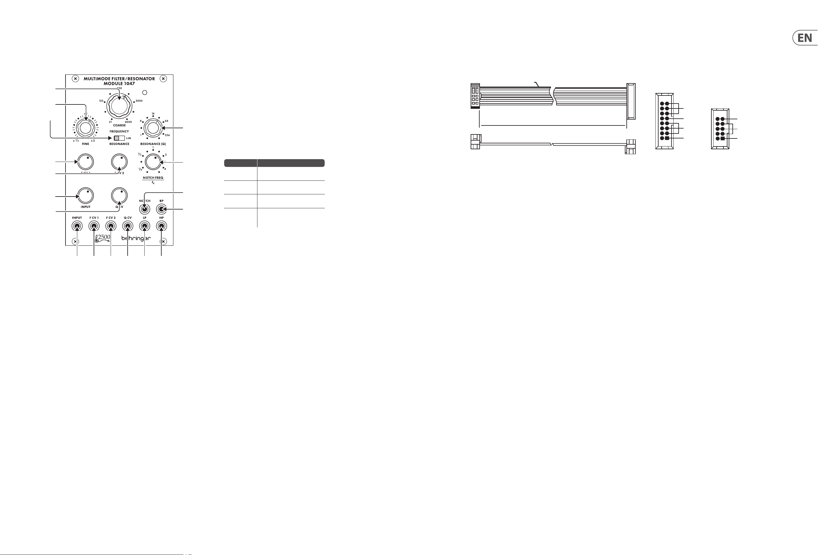
Controls
Power Connection
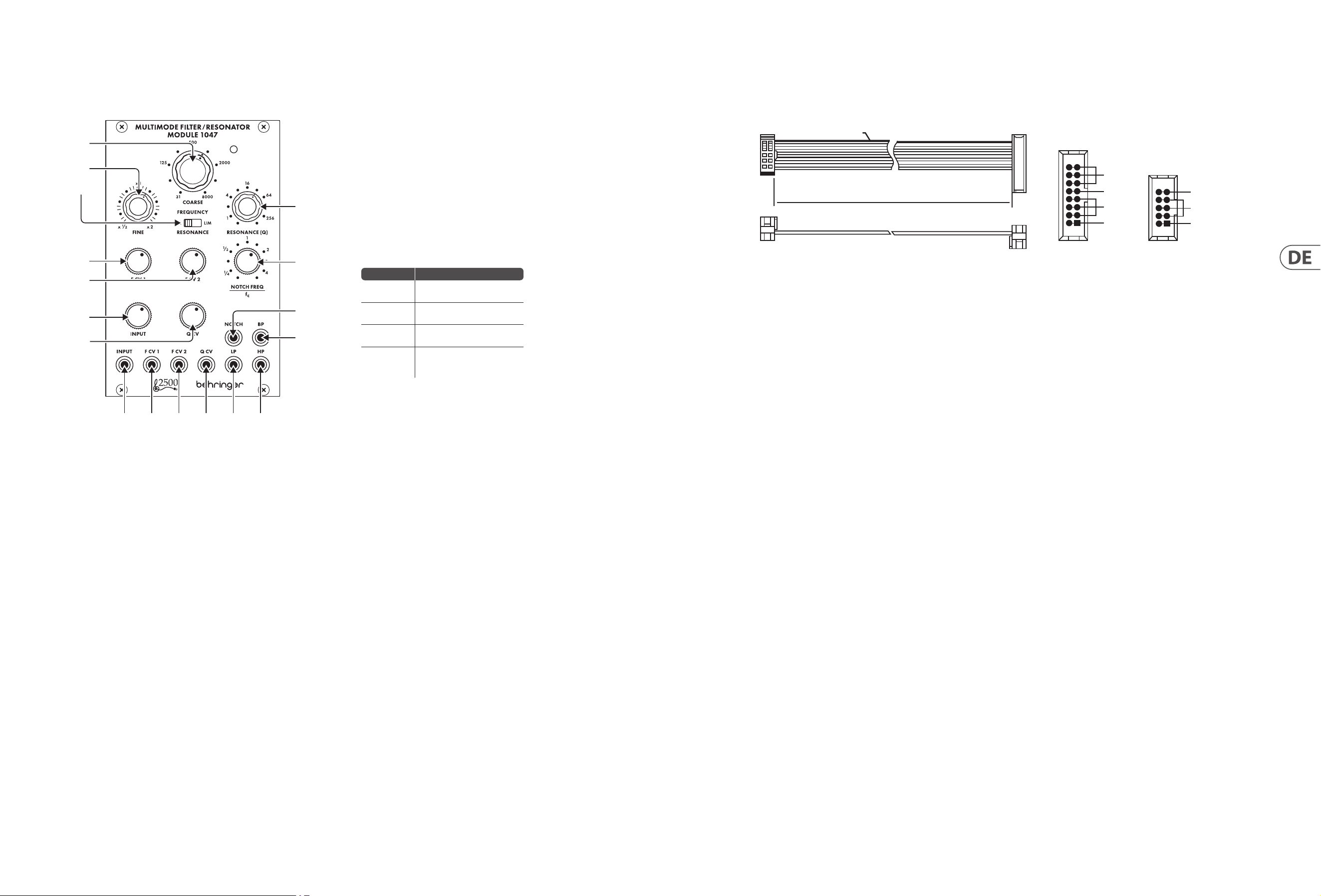
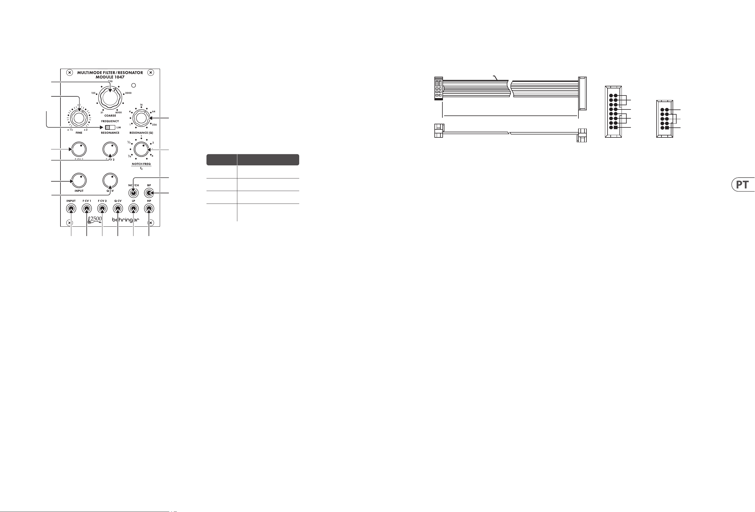
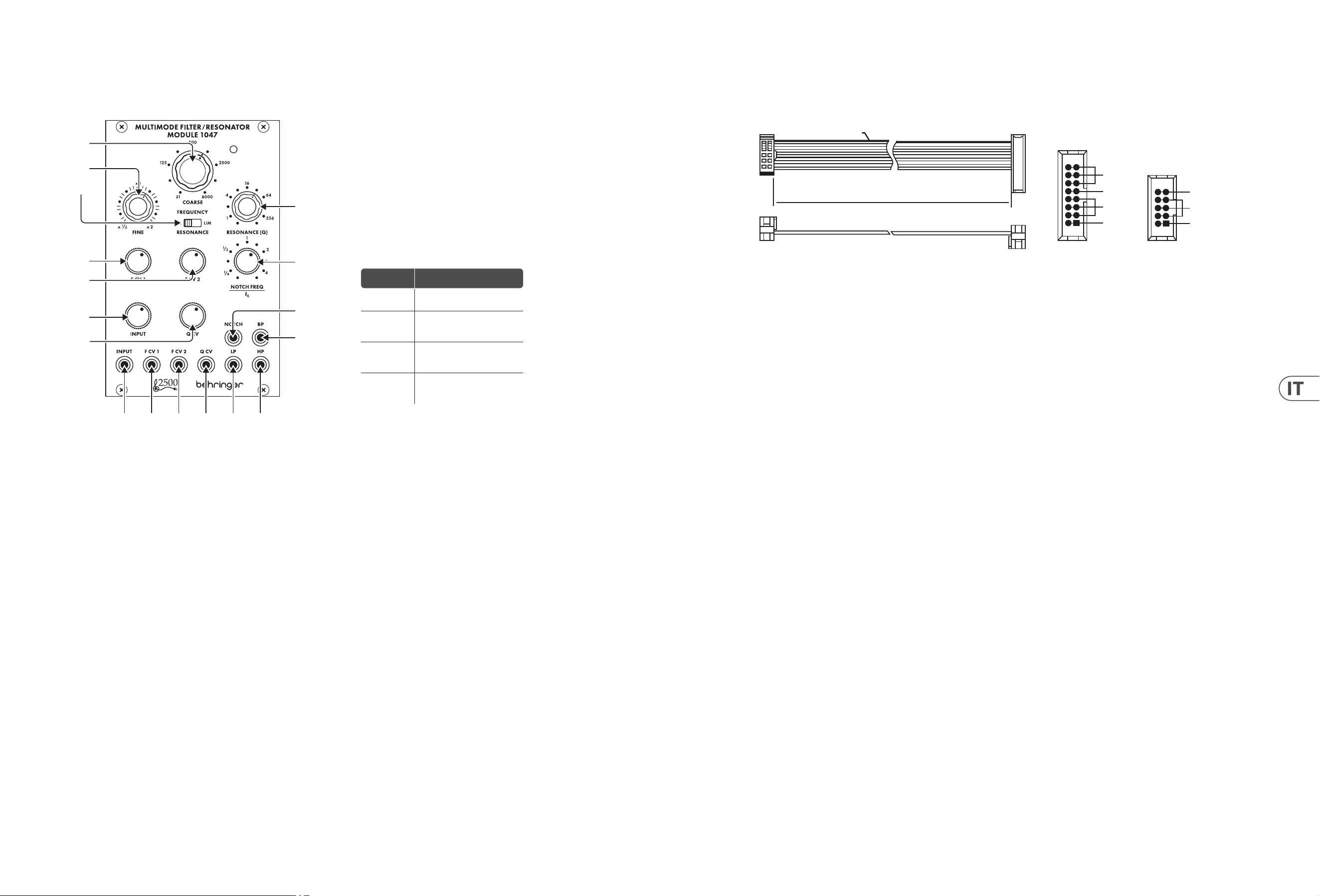
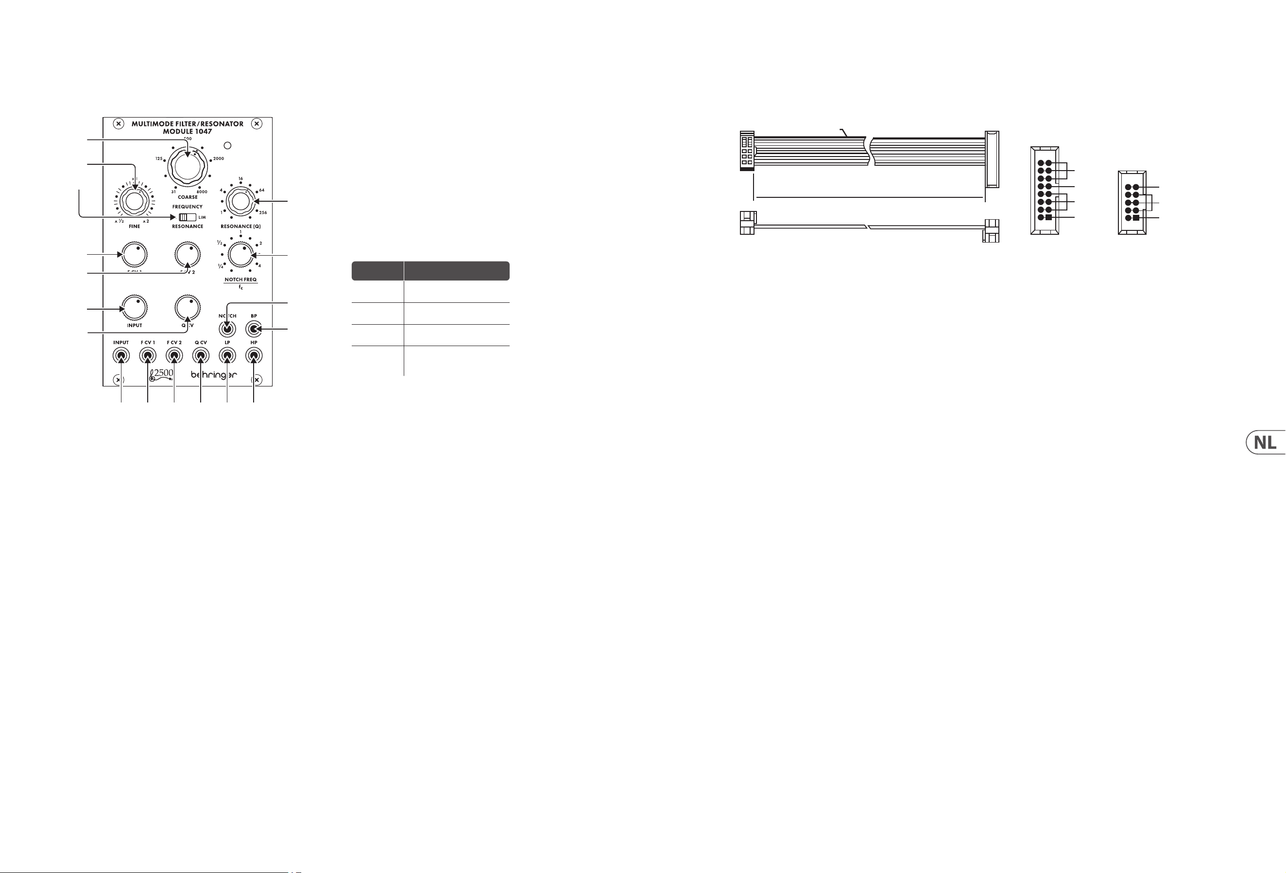
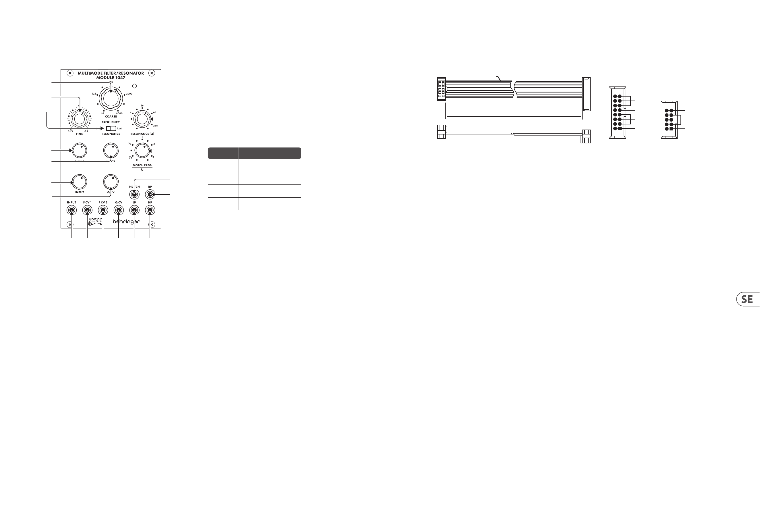
1. COARSE – Use this knob to dial in the general frequency area you want for
the high-pass threshold, low-pass threshold, band-pass center frequency
and notch lter center frequency, then go to the FINE knob to rene the
frequency setting. The frequency set by the COARSE and FINE knobs (“fc”)
will be used simultaneously for every lter in the module.
2. FINE – Use this knob to rene and focus the frequency set by the COARSE
FREQUENCY knob.
3. RESONANCE (NORM/LIM) – This sliding switch lets you choose between
normal resonance mode (NORM) and limiting mode (LIM), which limits the
height of a lter’s resonant peak. The LIM setting prevents circuit overload
when focusing a lter on a strong harmonic or fundamental frequency,
especially at high Q settings on the RESONANCE (Q) knob. In other situations,
the LIM setting can result in a very low output signal, and so the NORM setting
is usually preferred.
4. RESONANCE (Q) – This knob controls the width/smoothness and narrowness/
sharpness of the lter curves. At low Q settings, the lter curves are wider
and smoother, with a gentler eect on the sound (except for the notch lter,
whichfunctions most eectively at low Q settings). As you increase the
Qsetting, the lter curves gradually become narrower and sharper, which
can help you to focus in on narrow frequency bands. At higher Q settings, the
various lters can produce resonant peaks in the lter curves that boost some
frequencies and may require moving the RESONANCE (NORM/LIM) switch to
the LIM setting to prevent overloading the circuit (or the INPUT attenuator
knob can be turneddown).
5. F CV 1 – This knob adjusts the strength of the control voltage signal coming in
through the F CV 1 jack.
6. F CV 2 – This knob adjusts the strength of the control voltage signal coming in
through the F CV 2 jack.
7. NOTCH FEQUENCY/fc – Use this knob to oset the notch lter’s center
frequency (“fc”) set by the COARSE and FINE frequency controls. For standard
notch lter behavior, the NOTCH FREQ/fc control should be set to “1” on the
scale. This standard setting can then be tweaked by moving the NOTCH FREQ/fc
knob very slightly around “1”. Also, if higher Q values are added via the
RESONANCE knob while the notch lter is oset from fc, the higher Q values
result in a resonant peak at fc, with the notch at the point set by the NOTCH
FREQ/fc knob.
8. INPUT – This knob adjusts the strength of the audio signal coming through
the INPUT jack.
9. Q CV – This knob adjusts the strength of the Q control voltage signal coming in
through the Q CV jack.
10. INPUT – Use this jack to route audio signals into the module via cables with
3.5 mm connectors. You can also route in a keyboard gate signal to “ring” the
lter and produce a unique percussive sound when you press a key.
11. F CV 1 – Use this jack to route external control voltage or modulation signals
for the lter frequency setting into the module via cables with 3.5 mm
connectors.
12. F CV 2 – Use this jack to route external control voltage or modulation signals
for the lter frequency setting into the module via cables with 3.5 mm
connectors.
13. Q CV – Use this jack to route external control voltage signals for the
RESONANCE (Q) setting into the module via cables with 3.5 mm connectors.
14. LP – This jack sends out the nal signal from the low-pass lter via cables with
3.5 mm connectors.
15. HP – This jack sends out the nal signal from the high-pass lter via cables
with 3.5 mm connectors.
16. NOTCH – This jack sends out the nal signal from the notch lter via cables
with 3.5 mm connectors.
17. BP – This jack sends out the nal signal from the band-pass lter via cables
with 3.5 mm connectors.
Knob Setting Eect
Full CCW
Notch lter output becomes a
copy of the high-pass output
CCW to ¼
Notch frequency shifts
signicantly below fc
CW to 4
Notch frequency shifts
signicantly above fc
Full CW
Notch lter output becomes a
copy of the low-pass
lter output
The MULTIMODE FILTER / RESONATOR MODULE 1047 module comes with the
required power cable for connecting to a standard Eurorack power supply
system. Follow these steps to connect power to the module. It is easier to make
these connections before the module has been mounted into a rack case.
1. Turn the power supply or rack case power o and disconnect the
powercable.
2. Insert the 16-pin connector on the power cable into the socket on the power
supply or rack case. The connector has a tab that will align with the gap in the
socket, so it cannot be inserted incorrectly. If the power supply does not have a
keyed socket, be sure to orient pin 1 (-12 V) with the red stripe on the cable.
3. Insert the 10-pin connector into the socket on the back of the module.
Theconnector has a tab that will align with the socket for correct orientation.
4. After both ends of the power cable have been securely attached, you may
mount the module in a case and turn on the power supply.
Installation
The necessary screws are included with the module for mounting in a
Eurorackcase. Connectthe power cable before mounting.
Depending on the rack case, there may be a series of xed holes spaced 2 HP
apart along the length of the case, or a track that allows individual threaded
plates to slide along the length of the case. The free-moving threaded plates
allow precise positioning of the module, but each plate should be positioned in
the approximate relation to the mounting holes in your module before attaching
the screws.
Hold the module against the Eurorack rails so that each of the mounting holes
are aligned with a threaded rail or threaded plate. Attach the screws part way
to start, which will allow small adjustments to the positioning while you get
them all aligned. After the nal position has been established, tighten the
screwsdown.
HOT USED
Red Stripe
200 mm ± 10
15 16
21
P2P1
2
10 9
1
Connect end P1 to the module socket
Connect end P2 to the power supply
+ 12 V
- 12 V
GROUND
+ 12 V
- 12 V
GROUND
(1)
(2)
(3)
(4)
(5)
(6)
(7)
(8)
(9)
(10) (11) (12) (13) (14) (15)
(17)
(16)

8 MULTIMODE FILTER / RESONATOR MODULE 1047 Quick Start Guide 9
MULTIMODE FILTER / RESONATOR MODULE 1047
Controles
Conexión Eléctrica
El módulo MÓDULO DE FILTRO / RESONADOR MULTIMODO 1047 viene con el
cable de alimentación necesario para conectarse a un sistema de alimentación
estándar Eurorack. Siga estos pasos para conectar la alimentación al módulo.
Esmás fácil realizar estas conexiones antes de que el módulo se haya montado
enuna caja de rack.
1. Apague la fuente de alimentación o la caja del bastidor y desconecte el cable
dealimentación.
2. Inserte el conector de 16 clavijas del cable de alimentación en la toma de la
fuente de alimentación o en la caja del bastidor. El conector tiene una pestaña
que se alineará con el espacio en el zócalo, por lo que no se puede insertar
incorrectamente. Si la fuente de alimentación no tiene un enchufe con llave,
asegúrese de orientar el pin 1 (-12 V) con la raya roja en el cable.
3. Inserte el conector de 10 pines en el zócalo en la parte posterior del módulo.
Elconector tiene una pestaña que se alineará con el enchufe para una
orientación correcta.
4. Una vez que ambos extremos del cable de alimentación se hayan conectado
de forma segura, puede montar el módulo en una caja y encender la fuente
dealimentación.
Instalación
Los tornillos necesarios se incluyen con el módulo para el montaje en una caja
Eurorack. Conecte el cable de alimentación antes del montaje.
Dependiendo de la caja del bastidor, puede haber una serie de oricios jos
separados 2 HP a lo largo de la caja, o una pista que permita que las placas
roscadas individuales se deslicen a lo largo de la caja. Las placas roscadas de
movimiento libre permiten un posicionamiento preciso del módulo, pero cada
placa debe colocarse en una relación aproximada con los oricios de montaje en
su módulo antes de colocar los tornillos.
Sostenga el módulo contra los rieles Eurorack de modo que cada uno de los
oricios de montaje esté alineado con un riel o placa roscada. Coloque los
tornillos parcialmente para comenzar, lo que permitirá pequeños ajustes en
la posición mientras los alinea todos. Una vez establecida la posición nal,
aprietelos tornillos.
1. COARSE – Utilice esta perilla para marcar en el área de frecuencia general
que desee para el umbral de paso alto, el umbral de paso bajo, la frecuencia
central de paso de banda y la frecuencia central del ltro de muesca,
luego vaya a la perilla FINE para renar la conguración de frecuencia.
La frecuencia establecida por las perillas COARSE y FINE (“fc”) se usará
simultáneamente para cada ltro en el módulo.
2. FINE – Utilice esta perilla para renar y enfocar la frecuencia establecida por la
perilla COARSE FREQUENCY.
3. RESONANCE (NORM/LIM) – Este interruptor deslizante le permite elegir
entre el modo de resonancia normal (NORM) y el modo de limitación (LIM),
que limita la altura del pico resonante de un ltro. La conguración LIM
evita la sobrecarga del circuito cuando se enfoca un ltro en una frecuencia
fundamental o armónica fuerte, especialmente en conguraciones Q altas en la
perilla RESONANCE (Q). En otras situaciones, el ajuste LIM puede resultar en una
señal de salida muy baja, por lo que generalmente se preere el ajuste NORM.
4. RESONANCE (Q) – Esta perilla controla el ancho / suavidad y la estrechez /
nitidez de las curvas de ltro. En conguraciones de Q baja, las curvas de ltro
son más anchas y suaves, con un efecto más suave en el sonido (excepto por
el ltro notch, que funciona de manera más efectiva en conguraciones de
Q baja). A medida que aumenta el ajuste de Q, las curvas de ltro se vuelven
gradualmente más estrechas y nítidas, lo que puede ayudarlo a concentrarse
en bandas de frecuencia estrechas. En conguraciones de Q más altas,
losdiversos ltros pueden producir picos resonantes en las curvas de ltro
que aumentan algunas frecuencias y pueden requerir mover el interruptor
RESONANCE (NORM / LIM) a la conguración LIM para evitar sobrecargar el
circuito (o se puede girar la perilla del atenuador INPUT abajo).
5. F CV 1 – Esta perilla ajusta la fuerza de la señal de voltaje de control que
ingresa a través de la toma F CV 1.
6. F CV 2 – Esta perilla ajusta la fuerza de la señal de voltaje de control que
ingresa a través de la toma F CV 2.
7. NOTCH FEQUENCY/fc – Utilice esta perilla para compensar la frecuencia
central del ltro de muesca (“fc”) establecida por los controles de frecuencia
COARSE y FINE. Para el comportamiento del ltro de muesca estándar,
el control NOTCH FREQ / fc debe establecerse en “1” en la escala.Este ajuste
estándar se puede modicar moviendo la perilla NOTCH FREQ / fc muy
ligeramente alrededor de “1”. Además, si se agregan valores de Q más altos a
través de la perilla RESONANCE mientras el ltro de muesca está desplazado de
fc, los valores de Q más altos dan como resultado un pico resonante en fc, con
la muesca en el punto establecido por la perilla NOTCH FREQ / fc.
8. INPUT – Esta perilla ajusta la fuerza de la señal de audio que llega a través de
la toma INPUT.
9. Q CV – Esta perilla ajusta la fuerza de la señal de voltaje de control Q que
ingresa a través del conector Q CV.
10. INPUT – Utilice este conector para enrutar señales de audio al módulo a través
de cables con conectores de 3,5 mm. También puede enrutar una señal de
puerta de teclado para “hacer sonar” el ltro y producir un sonido de percusión
único cuando presiona una tecla.
11. F CV 1 – Utilice este conector para enrutar señales de modulación o voltaje de
control externo para la conguración de la frecuencia del ltro en el módulo a
través de cables con conectores de 3,5 mm.
12. F CV 2 – Utilice este conector para enrutar señales de modulación o voltaje de
control externo para la conguración de la frecuencia del ltro en el módulo a
través de cables con conectores de 3,5 mm.
13. Q CV – Utilice este conector para enrutar señales de voltaje de control externo
para la conguración de RESONANCIA (Q) en el módulo a través de cables con
conectores de 3,5 mm.
14. LP – Este conector envía la señal nal del ltro de paso bajo a través de cables
con conectores de 3,5 mm.
15. HP – Este conector envía la señal nal del ltro de paso alto a través de cables
con conectores de 3,5 mm.
16. NOTCH – Este conector envía la señal nal del ltro de muesca a través de
cables con conectores de 3,5 mm.
17. BP –Este conector envía la señal nal del ltro de paso de banda a través de
cables con conectores de 3,5 mm.
HOT USED
Red Stripe
200 mm ± 10
15 16
21
P2P1
2
10 9
1
Connect end P1 to the module socket
Connect end P2 to the power supply
+ 12 V
- 12 V
GROUND
+ 12 V
- 12 V
GROUND
(1)
(2)
(3)
(4)
(5)
(6)
(7)
(8)
(9)
(10) (11) (12) (13) (14) (15)
(17)
(16)
Ajuste de
la perilla
Efecto
CCW
completa
La salida del ltro de muesca
se convierte en una copia de la
salida de paso alto
CCW a ¼
La frecuencia de la muesca
cambia signicativamente por
debajo de fc
CW a 4
La frecuencia de la muesca
cambia signicativamente por
encima de fc
CW
completo
La salida del ltro de muesca
se convierte en una copia de la
salida del ltro de paso bajo
10 MULTIMODE FILTER / RESONATOR MODULE 1047 Quick Start Guide 11
MULTIMODE FILTER / RESONATOR MODULE 1047
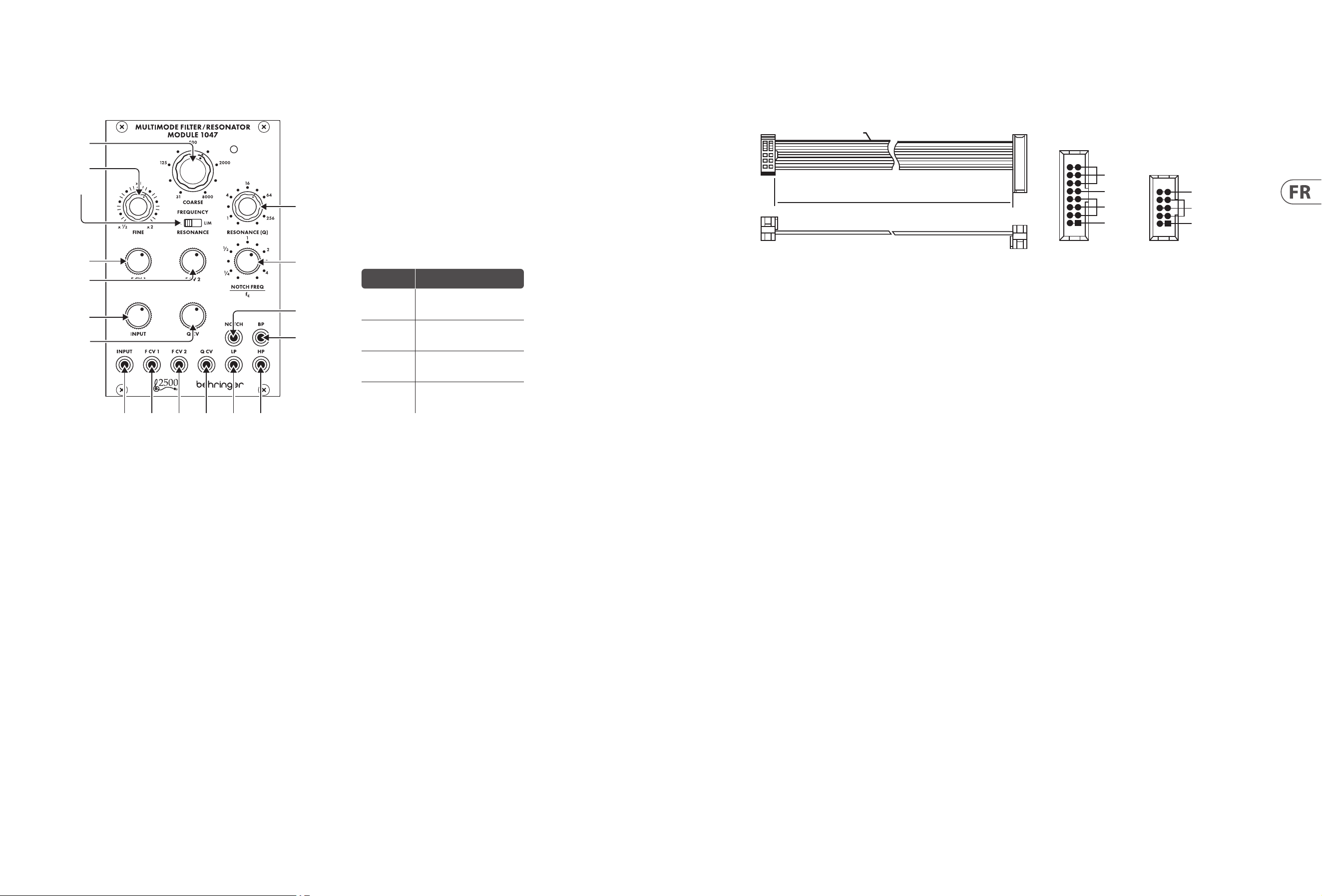
Réglages
Connexion Électrique
Le module MULTIMODE FILTRE / RÉSONATEUR MODULE 1047 est livré avec le
câble d’alimentation nécessaire pour se connecter à un système d’alimentation
standard Eurorack. Suivez ces étapes pour connecter l’alimentation au module.
Il est plus facile d’eectuer ces connexions avant que le module n’ait été monté
dans un boîtier de rack.
1. Mettez le bloc d’alimentation ou le boîtier de rack hors tension et débranchez
le câble d’alimentation.
2. Insérez le connecteur à 16 broches du câble d’alimentation dans la prise du
bloc d’alimentation ou du boîtier du rack. Le connecteur a une languette qui
s’alignera avec l’espace dans la prise, de sorte qu’il ne peut pas être inséré de
manière incorrecte. Silebloc d’alimentation n’a pas de prise à clé, veillez à
orienter la broche 1 (-12 V) avec la bande rouge sur le câble.
3. Insérez le connecteur à 10 broches dans la prise à l’arrière du module.
Leconnecteur a une languette qui s’alignera avec la prise pour une
orientationcorrecte.
4. Une fois que les deux extrémités du câble d’alimentation ont été
solidementxées, vouspouvez monter le module dans un boîtier et
allumerl’alimentation.
Installation
Les vis nécessaires sont incluses avec le module pour le montage dans un boîtier
Eurorack. Connectez le câble d’alimentation avant le montage.
Selon le cas de rack, il peut y avoir une série de trous xes espacés de 2 HP sur
la longueur du cas, ou une piste qui permet aux plaques letées individuelles
de glisser le long de la longueur du cas. Les plaques letées à déplacement libre
permettent un positionnement précis du module, mais chaque plaque doit être
positionnée approximativement par rapport aux trous de montage de votre
module avant de xer les vis.
Maintenez le module contre les rails Eurorack de sorte que chacun des trous
de montage soit aligné avec un rail leté ou une plaque letée. Fixez les vis
partiellementpour commencer, cequi permettra de petits ajustements au
positionnement pendant que vouslesalignereztous. Une fois la position nale
établie, serrez les vis vers le bas.
1. COARSE – Utilisez ce bouton pour composer la zone de fréquence générale
que vous souhaitez pour le seuil passe-haut, le seuil passe-bas, la fréquence
centrale du passe-bande et la fréquence centrale du ltre coupe-bande, puis
allez au bouton FINE pour aner le réglage de la fréquence. La fréquence
réglée par les boutons COARSE et FINE (« fc ») sera utilisée simultanément
pour chaque ltre du module.
2. FINE – Utilisez ce bouton pour aner et focaliser la fréquence dénie par le
bouton COARSE FREQUENCY.
3. RESONANCE (NORM/LIM) – Ce commutateur coulissant vous permet de
choisir entre le mode de résonance normal (NORM) et le mode de limitation
(LIM), qui limite la hauteur du pic de résonance d’un ltre. Le réglage LIM
empêche la surcharge du circuit lors de la focalisation d’un ltre sur une
fréquence harmonique ou fondamentale forte, en particulier à des réglages Q
élevés sur le bouton RESONANCE (Q). Dans d’autres situations, le réglage LIM
peut entraîner un signal de sortie très faible, c’est pourquoi le réglage NORM
est généralement préféré.
4. RESONANCE (Q) – Ce bouton contrôle la largeur/lissage et l’étroitesse/netteté
des courbes du ltre. Avec des réglages de Q bas, les courbes de ltre sont
plus larges et plus lisses, avec un eet plus doux sur le son (sauf pour le ltre
coupe-bande, qui fonctionne plus ecacement avec des réglages de Q bas).
Au fur et à mesure que vous augmentez le réglage Q, les courbes de ltre
deviennent progressivement plus étroites et plus nettes, ce qui peut vous aider
à vous concentrer sur des bandes de fréquences étroites. À des réglages de Q
plus élevés, les diérents ltres peuvent produire des pics de résonance dans
les courbes de ltre qui amplient certaines fréquences et peuvent nécessiter
de déplacer le commutateur RESONANCE (NORM/LIM) sur le réglage LIM pour
éviter de surcharger le circuit (ou le bouton d’atténuateur INPUT peut être
tourné vers le bas).
5. F CV 1 – Ce bouton ajuste la force du signal de tension de commande entrant
par la prise F CV 1.
6. F CV 2 – Ce bouton ajuste la force du signal de tension de commande entrant
par la prise F CV 2.
7. NOTCH FEQUENCY/fc – Utilisez ce bouton pour décaler la fréquence centrale
du ltre coupe-bande (« fc ») dénie par les commandes de fréquence COARSE
et FINE. Pour un comportement de ltre coupe-bande standard, la commande
NOTCH FREQ/fc doit être réglée sur «1» sur l’échelle. Ce réglage standard peut
ensuite être modié en déplaçant très légèrement le bouton NOTCH FREQ/
fc autour de «1». De plus, si des valeurs Q plus élevées sont ajoutées via le
bouton RESONANCE alors que le ltre coupe-bande est décalé par rapport à fc,
les valeurs Q plus élevées entraînent un pic de résonance à fc, avec le coupe-
bande au point déni par le bouton NOTCH FREQ/fc.
8. INPUT – Ce bouton ajuste la force du signal audio provenant de la prise INPUT.
9. Q CV – Ce bouton ajuste la force du signal de tension de commande Q entrant
par la prise Q CV.
10. INPUT – Utilisez cette prise pour acheminer les signaux audio dans le module
via des câbles avec des connecteurs de 3,5 mm. Vous pouvez également
acheminer un signal de gate de clavier pour « faire sonner » le ltre et produire
un son de percussion unique lorsque vous appuyez sur une touche.
11. F CV 1 – Utilisez cette prise pour acheminer la tension de commande externe
ou les signaux de modulation pour le réglage de la fréquence du ltre dans le
module via des câbles avec des connecteurs de 3,5 mm.
12. F CV 2 – Utilisez cette prise pour acheminer la tension de commande externe
ou les signaux de modulation pour le réglage de la fréquence du ltre dans le
module via des câbles avec des connecteurs de 3,5 mm.
13. Q CV – Utilisez cette prise pour acheminer les signaux de tension de
commande externes pour le réglage RESONANCE (Q) dans le module via des
câbles avec des connecteurs de 3,5 mm.
14. LP – Cette prise envoie le signal nal du ltre passe-bas via des câbles avec des
connecteurs de 3,5 mm.
15. HP – Cette prise envoie le signal nal du ltre passe-haut via des câbles avec
des connecteurs de 3,5 mm.
16. NOTCH – Cette prise envoie le signal nal du ltre coupe-bande via des câbles
avec des connecteurs de 3,5 mm.
17. BP – Cette prise envoie le signal nal du ltre passe-bande via des câbles avec
des connecteurs de 3,5 mm.
HOT USED
Red Stripe
200 mm ± 10
15 16
21
P2P1
2
10 9
1
Connect end P1 to the module socket
Connect end P2 to the power supply
+ 12 V
- 12 V
GROUND
+ 12 V
- 12 V
GROUND
(1)
(2)
(3)
(4)
(5)
(6)
(7)
(8)
(9)
(10) (11) (12) (13) (14) (15)
(17)
(16)
Réglage
du bouton
Eet
CCW
complet
La sortie du ltre coupe-
bande devient une copie de la
sortie passe-haut
CCW à ¼
La fréquence d'encoche se
décale nettement en dessous
de fc
CW à 4
La fréquence d'encoche se
décale considérablement
au-dessus de fc
Full CW
La sortie du ltre coupe-bande
devient une copie de la sortie
du ltre passe-bas
12 MULTIMODE FILTER / RESONATOR MODULE 1047 Quick Start Guide 13
MULTIMODE FILTER / RESONATOR MODULE 1047
Bedienelemente
Netzanschluss
Das Modul MULTIMODE FILTER / RESONATOR MODUL 1047 wird mit dem
erforderlichen Netzkabel zum Anschluss an ein Standard-Eurorack-
Stromversorgungssystem geliefert. Befolgen Sie diese Schritte, um das
Modulmit Strom zu verbinden. Es ist einfacher, diese Verbindungen herzustellen,
bevor das Modul in ein Rackgehäuse eingebaut wurde.
1. Schalten Sie das Netzteil oder das Rackgehäuse aus und ziehen Sie das
Netzkabel ab.
2. Stecken Sie den 16-poligen Stecker am Netzkabel in die Buchse am
Netzteiloder im Rack-Gehäuse. Der Anschluss verfügt über eine Lasche, diean
der Lücke in der Buchse ausgerichtet ist, sodass sie nicht falsch eingeführt
werden kann. Wenn das Netzteil keine Schlüsselbuchse hat, achten Sie darauf,
Pin 1 (-12 V) mit dem roten Streifen am Kabelauszurichten.
3. Stecken Sie den 10-poligen Stecker in die Buchse auf der Rückseite des Moduls.
DerAnschluss verfügt über eine Lasche, die zur korrekten Ausrichtung an der
Buchseausgerichtet wird.
4. Nachdem beide Enden des Netzkabels fest angeschlossen wurden, können Sie
das Modul in einem Gehäuse montieren und die Stromversorgung einschalten.
Installation
Die erforderlichen Schrauben sind im Lieferumfang des Moduls für die Montage
in einem Eurorack-Gehäuse enthalten. Schließen Sie das Netzkabel vor der
Montage an.
Abhängig vom Rack-Gehäuse kann es eine Reihe von festen Löchern geben,
die entlang der Länge des Gehäuses 2 PS voneinander entfernt sind, oder eine
Schiene, mit der einzelne Gewindeplatten entlang der Länge des Gehäuses
gleiten können. Die frei beweglichen Gewindeplatten ermöglichen eine
präzise Positionierung des Moduls. Jede Platte sollte jedoch in der ungefähren
Beziehung zu den Befestigungslöchern in Ihrem Modul positioniert werden,
bevor Sie die Schrauben anbringen.
Halten Sie das Modul so gegen die Eurorack-Schienen, dass jedes der
Befestigungslöcher mit einer Gewindeschiene oder einer Gewindeplatte
ausgerichtet ist. BringenSie die Schrauben teilweise an, um zu beginnen.
Dadurch können Sie die Position geringfügig anpassen, während Sie alle
ausrichten. Ziehen Sie die Schraubenfest, nachdem die endgültige Position
festgelegt wurde.
1. COARSE – Verwenden Sie diesen Regler, um den gewünschten allgemeinen
Frequenzbereich für den Hochpass-Schwellenwert, den Tiefpass-Schwellenwert,
die Bandpass-Mittenfrequenz und die Notchlter-Mittenfrequenz einzustellen,
und gehen Sie dann zum FINE-Regler, um die Frequenzeinstellung zu verfeinern.
Die mit den COARSE- und FINE-Reglern („fc“) eingestellte Frequenz wird
gleichzeitig für alle Filter im Modul verwendet.
2. FINE – Verwenden Sie diesen Regler, um die mit dem COARSE FREQUENCY-
Regler eingestellte Frequenz zu verfeinern und zu fokussieren.
3. RESONANCE (NORM/LIM) – Mit diesem Schiebeschalter können Sie zwischen
dem normalen Resonanzmodus (NORM) und dem Begrenzungsmodus (LIM)
wählen, der die Höhe der Resonanzspitze eines Filters begrenzt. Die LIM-
Einstellung verhindert eine Überlastung der Schaltung, wenn ein Filter auf eine
starke Oberwelle oder Grundfrequenz fokussiert wird, insbesondere bei hohen
Q-Einstellungen am RESONANCE (Q)-Regler. In anderen Situationen kann die
LIM-Einstellung zu einem sehr niedrigen Ausgangssignal führen, daher wird
normalerweise die NORM-Einstellung bevorzugt.
4. RESONANCE (Q) – Dieser Regler steuert die Breite/Glätte und Schmalheit/
Schärfe der Filterkurven. Bei niedrigen Q-Einstellungen sind die Filterkurven
breiter und glatter, mit einer sanfteren Wirkung auf den Klang (mit Ausnahme
des Notch-Filters, der bei niedrigen Q-Einstellungen am eektivsten
funktioniert). Wenn Sie die Q-Einstellung erhöhen, werden die Filterkurven
allmählich schmaler und schärfer, was Ihnen helfen kann, sich auf schmale
Frequenzbänder zu konzentrieren. Bei höheren Q-Einstellungen können die
verschiedenen Filter Resonanzspitzen in den Filterkurven erzeugen, die einige
Frequenzen anheben, und es kann erforderlich sein, den RESONANCE (NORM/
LIM)-Schalter auf die LIM-Einstellung zu stellen, um eine Übersteuerung der
Schaltung zu verhindern (oder der INPUT-Dämpfungsregler kann gedreht
werden). Nieder).
5. F CV 1 – Dieser Regler stellt die Stärke des Steuerspannungssignals
ein, das über die F CV 1-Buchse eingeht.
6. F CV 2 – Dieser Regler stellt die Stärke des Steuerspannungssignals ein, das über die
FCV 2-Buchse eingeht.
7. NOTCH FEQUENCY/fc – Verwenden Sie diesen Regler, um die mit den
Frequenzreglern COARSE und FINE eingestellte Mittenfrequenz des Notch-
Filters („fc“) zu verschieben. Für das Standardverhalten des Notch-Filters sollte
der NOTCH FREQ/fc-Regler auf der Skala auf „1“ gestellt werden. Diese
Standardeinstellung kann dann optimiert werden, indem Sie den NOTCH FREQ/
fc-Regler ganz leicht um „1“ drehen. Auch wenn über den RESONANCE-Regler
höhere Q-Werte hinzugefügt werden, während der Notch-Filter von fc versetzt
ist, führen die höheren Q-Werte zu einer resonanten Spitze bei fc, wobei die
Kerbe an dem mit dem NOTCH FREQ/fc-Regler eingestellten Punktliegt.
8. INPUT – Dieser Regler stellt die Stärke des Audiosignals ein, das über die
INPUT-Buchse kommt.
9. Q CV – Dieser Regler stellt die Stärke des Q-Steuerspannungssignals ein, das
über die Q CV- Buchse eingeht.
10. INPUT – Verwenden Sie diese Buchse, um Audiosignale über Kabel mit
3,5-mm-Steckern in das Modul zu leiten. Sie können auch ein Keyboard-Gate-Signal
einleiten, um das Filter „klingeln“ zu lassen und einen einzigartigen perkussiven
Sound zu erzeugen, wenn Sie eine Taste drücken.
11. F CV 1 – Verwenden Sie diese Buchse, um externe Steuerspannungen
oder Modulationssignale für die Filterfrequenzeinstellung über Kabel mit
3,5-mm-Steckern in das Modul zu leiten.
12. F CV 2 – Verwenden Sie diese Buchse, um externe Steuerspannungen
oder Modulationssignale für die Filterfrequenzeinstellung über Kabel mit
3,5-mm-Steckern in das Modul zu leiten.
13. Q CV – Verwenden Sie diese Buchse, um externe Steuerspannungssignale
fürdie Einstellung RESONANCE (Q) über Kabel mit 3,5-mm-Steckern in das
Modul zu leiten.
14. LP – Diese Buchse sendet das endgültige Signal des Tiefpasslters über
Kabelmit 3,5-mm-Steckern aus.
15. HP – Diese Buchse sendet das endgültige Signal des Hochpasslters über
Kabel mit 3,5-mm-Steckern aus.
16. NOTCH – Diese Buchse sendet das endgültige Signal des Notchlters über
Kabel mit 3,5-mm-Steckern aus.
17. BP – Diese Buchse sendet das endgültige Signal des Bandpasslters über
Kabel mit 3,5-mm-Steckern.
Knob Setting Eect
Full CCW
Notch lter output becomes a
copy of the high-pass output
CCW to ¼
Notch frequency shifts
signicantly below fc
CW to 4
Notch frequency shifts
signicantly above fc
Full CW
Notch lter output becomes
a copy of the low-pass lter
output
HOT USED
Red Stripe
200 mm ± 10
15 16
21
P2P1
2
10 9
1
Connect end P1 to the module socket
Connect end P2 to the power supply
+ 12 V
- 12 V
GROUND
+ 12 V
- 12 V
GROUND
(1)
(2)
(3)
(4)
(5)
(6)
(7)
(8)
(9)
(10) (11) (12) (13) (14) (15)
(17)
(16)
14 MULTIMODE FILTER / RESONATOR MODULE 1047 Quick Start Guide 15
MULTIMODE FILTER / RESONATOR MODULE 1047
Controles
Conexão de Força
O módulo MULTIMODE FILTER / RESONATOR MODULE 1047 vem com o cabo de
alimentação necessário para conectar a um sistema de fonte de alimentação
Eurorack padrão. Siga estas etapas para conectar a alimentação ao módulo.
É mais fácil fazer essas conexões antes que o módulo seja montado em um
gabinete de rack.
1. Desligue a fonte de alimentação ou o gabinete do rack e desconecte o cabo
dealimentação.
2. Insira o conector de 16 pinos do cabo de alimentação no soquete da fonte
de alimentação ou no gabinete do rack. O conector possui uma aba que
se alinhará com a lacuna no soquete, de forma que não pode ser inserido
incorretamente. Se a fonte de alimentação não tiver um soquete chaveado,
certique-se de orientar o pino 1 (-12 V) com a faixa vermelha no cabo.
3. Insira o conector de 10 pinos no soquete na parte traseira do módulo.
Oconector possui uma guia que se alinha ao soquete para orientação correta.
4. Depois que ambas as extremidades do cabo de alimentação forem
rmementeconectadas, você pode montar o módulo em um gabinete e ligar a
fonte de alimentação.
Instalação
Os parafusos necessários estão incluídos com o módulo para montagem em uma
caixa Eurorack. Conecte o cabo de alimentação antes da montagem.
Dependendo da caixa do rack, pode haver uma série de orifícios xos espaçados
de 2 HP ao longo do comprimento da caixa, ou um trilho que permite que placas
roscadas individuais deslizem ao longo do comprimento da caixa. As placas
roscadas de movimento livre permitem o posicionamento preciso do módulo,
mas cada placa deve ser posicionada em uma relação aproximada com os orifícios
de montagem em seu módulo antes de prender os parafusos.
Segure o módulo contra os trilhos Eurorack de forma que cada um dos orifícios
de montagemque alinhado com um trilho ou placa rosqueada. Prenda os
parafusos parcialmente para começar, o que permitirá pequenos ajustes no
posicionamento enquantovocê os alinha. Depois de estabelecida a posição nal,
aperte os parafusos.
1. COARSE – Use este botão para selecionar a área de frequência geral
desejada para o limiar passa-alto, limiar passa-baixo, frequência central
passa-banda e frequência central do ltro de entalhe e, em seguida, vá até o
botão FINE para renar a conguração da frequência. A frequência denida
pelos botões COARSE e FINE (“fc”) será usada simultaneamente para cada
ltro no módulo.
2. FINE – Use este botão para renar e focalizar a frequência denida pelo botão
COARSE FREQUENCY.
3. RESONANCE (NORM/LIM) – This sliding switch lets you choose between
normal resonance mode (NORM) and limiting mode (LIM), which limits the
height of a lter’s resonant peak. The LIM setting prevents circuit overload
when focusing a lter on a strong harmonic or fundamental frequency,
especially at high Q settings on the RESONANCE (Q) knob. In other situations,
the LIM setting can result in a very low output signal, and so the NORM setting
is usually preferred.
4. RESONANCE (Q) – Este botão controla a largura / suavidade e estreiteza /
nitidez das curvas do ltro. Em congurações de Q baixas, as curvas do ltro
são mais largas e suaves, com um efeito mais suave no som (exceto para o
ltro notch, que funciona mais efetivamente em congurações de Q baixas).
Conforme você aumenta a conguração Q, as curvas do ltro tornam-se
gradualmente mais estreitas e nítidas, o que pode ajudá-lo a se concentrar em
bandas de frequência estreitas. Em congurações de Q mais altas, os vários
ltros podem produzir picos ressonantes nas curvas do ltro que aumentam
algumas frequências e podem exigir a mudança da chave RESONANCE (NORM /
LIM) para a conguração LIM para evitar sobrecarregar o circuito
(ou o botão atenuador INPUT pode ser girado baixa).
5. F CV 1 – Este botão ajusta a força do sinal de tensão de controle que chega
através do conector F CV 1.
6. F CV 2 – Este botão ajusta a força do sinal de tensão de controle que entra pelo
conector F CV 2.
7. NOTCH FEQUENCY/fc – Use este botão para compensar a frequência central
do ltro de entalhe (“fc”) denida pelos controles de frequência COARSE e
FINE. Para o comportamento do ltro notch padrão, o controle NOTCH FREQ /
fc deve ser denido como “1” na escala. Esta conguração padrão pode então
ser ajustada movendo o botão NOTCH FREQ / fc levemente em torno de “1”.
Além disso, se valores de Q mais altos forem adicionados por meio do botão
RESONANCE enquanto o ltro de entalhe for deslocado de fc, os valores de Q
mais altos resultarão em um pico ressonante em fc, com o entalhe no ponto
denido pelo botão NOTCH FREQ / fc.
8. INPUT – Este botão ajusta a intensidade do sinal de áudio que chega através
do conector INPUT.
9. Q CV – Este botão ajusta a força do sinal de tensão de controle Q que entra
pelo conector Q CV.
10. INPUT – Use este conector para rotear sinais de áudio no módulo por meio
de cabos com conectores de 3,5 mm. Você também pode rotear um sinal de
porta de teclado para “tocar” o ltro e produzir um som percussivo exclusivo ao
pressionar uma tecla.
11. F CV 1 – Use este conector para rotear sinais de modulação ou tensão de
controle externo para a conguração de frequência do ltro no módulo por
meio de cabos com conectores de 3,5 mm.
12. F CV 2 – Use este conector para rotear sinais de modulação ou tensão de
controle externo para a conguração de frequência do ltro no módulo por
meio de cabos com conectores de 3,5 mm.
13. Q CV – Use este conector para rotear sinais de tensão de controle externo para
a conguração RESONANCE (Q) no módulo por meio de cabos com conectores
de 3,5 mm.
14. LP – Este conector envia o sinal nal do ltro passa-baixa por meio de cabos
com conectores de 3,5 mm.
15. HP – Este conector envia o sinal nal do ltro passa-alta por meio de cabos
com conectores de 3,5 mm.
16. NOTCH – Este conector envia o sinal nal do ltro notch por meio de cabos
com conectores de 3,5 mm.
17. BP – Este conector envia o sinal nal do ltro passa-banda por meio de cabos
com conectores de 3,5 mm.
HOT USED
Red Stripe
200 mm ± 10
15 16
21
P2P1
2
10 9
1
Connect end P1 to the module socket
Connect end P2 to the power supply
+ 12 V
- 12 V
GROUND
+ 12 V
- 12 V
GROUND
(1)
(2)
(3)
(4)
(5)
(6)
(7)
(8)
(9)
(10) (11) (12) (13) (14) (15)
(17)
(16)
Conguração
de botão
Efeito
CCW
completo
A saída do ltro notch torna-se
uma cópia da saída passa-alta
CCW
para ¼
A frequência de entalhe muda
signicativamente abaixo de fc
CW para 4
A frequência de entalhe muda
signicativamente acima de fc
Full CW
A saída do ltro notch torna-se
uma cópia da saída do ltro
passa-baixa
16 MULTIMODE FILTER / RESONATOR MODULE 1047 Quick Start Guide 17
MULTIMODE FILTER / RESONATOR MODULE 1047
Controlli
Connessione di Alimentazione
Il modulo 1047 FILTRO MULTIMODE / MODULO RISONATORE viene fornito
con il cavo di alimentazione necessario per il collegamento a un sistema
di alimentazione Eurorack standard. Seguire questi passaggi per collegare
l’alimentazione al modulo. È più facile eettuare questi collegamenti prima che il
modulo sia stato montato in una custodia rack.
1. Spegnere l’alimentatore o il case del rack e scollegare il cavo di alimentazione.
2. Inserire il connettore a 16 pin del cavo di alimentazione nella presa
sull’alimentatore o sulla custodia del rack. Il connettore ha una linguetta che
si allineerà con lo spazio nella presa, quindi non può essere inserito in modo
errato. Se l’alimentatore non dispone di una presa con chiave, assicurarsi di
orientare il pin 1 (-12 V) con la striscia rossa sul cavo.
3. Inserire il connettore a 10 pin nella presa sul retro del modulo. Il connettore ha
una linguetta che si allineerà con la presa per un corretto orientamento.
4. Dopo che entrambe le estremità del cavo di alimentazione sono state
ssatesaldamente, è possibile montare il modulo in una custodia e
accenderel’alimentatore.
Installazione
Le viti necessarie sono incluse con il modulo per il montaggio in una custodia
Eurorack. Collegare il cavo di alimentazione prima del montaggio.
A seconda del case del rack, potrebbero esserci una serie di fori ssi distanziati
di 2 HP l’uno dall’altro lungo la lunghezza del case, o un binario che consente
alle singole piastre lettate di scorrere lungo la lunghezza del case. Le piastre
lettate a movimento libero consentono un posizionamento preciso del modulo,
ma ciascuna piastra deve essere posizionata in relazione approssimativa con i fori
di montaggio nel modulo prima di ssare le viti.
Tenere il modulo contro le guide Eurorack in modo che ciascuno dei fori di
montaggio sia allineato con una guida lettata o una piastra lettata. Attacca le
viti in parte per iniziare, ilche consentirà piccoli aggiustamenti al posizionamento
mentre le fai allineare tutte. Dopoaver stabilito la posizione nale, serrare le viti.
1. COARSE – Utilizzare questa manopola per selezionare l’area di frequenza
generale desiderata per la soglia passa-alto, la soglia passa-basso, la
frequenza centrale passa banda e la frequenza centrale del ltro notch,
quindi andare alla manopola FINE per perfezionare l’impostazione della
frequenza. La frequenza impostata dalle manopole COARSE e FINE (“fc”)
verrà utilizzata contemporaneamente per ogni ltro del modulo.
2. FINE – Utilizzare questa manopola per perfezionare e focalizzare la frequenza
impostata dalla manopola COARSE FREQUENCY.
3. RESONANCE (NORM/LIM) – Questo interruttore a scorrimento consente
di scegliere tra la modalità di risonanza normale (NORM) e la modalità di
limitazione (LIM), che limita l’altezza del picco di risonanza di un ltro.
L’impostazione LIM previene il sovraccarico del circuito quando si focalizza
un ltro su una forte frequenza armonica o fondamentale, specialmente con
impostazioni Q elevate sulla manopola RESONANCE (Q). In altre situazioni,
l’impostazione LIM può portare a un segnale di uscita molto basso, quindi
l’impostazione NORM è generalmente preferita.
4. RESONANCE (Q) – Questa manopola controlla la larghezza/uniformità e
la ristrettezza/nitidezza delle curve del ltro. Con impostazioni Q basse,
lecurve del ltro sono più ampie e uniformi, con un eetto più delicato
sul suono (adeccezione del ltro notch, che funziona in modo più ecace
con impostazioni Q basse). Aumentando l’impostazione Q, le curve del
ltro diventano gradualmente più strette e nitide, il che può aiutarti a
concentrarti su bande di frequenza strette. A impostazioni Q più alte, i vari
ltri possono produrre picchi risonanti nelle curve del ltro che amplicano
alcune frequenzee potrebbe richiedere lo spostamento dell’interruttore
RESONANCE(NORM/LIM) sull’impostazione LIM per evitare di sovraccaricare il
circuito (oppure è possibile ruotare la manopola dell’attenuatore INPUT giù).
5. F CV 1 – Questa manopola regola l’intensità del segnale di tensione di
controllo che arriva attraverso il jack F CV 1.
6. F CV 2 – Questa manopola regola l’intensità del segnale di tensione di
controllo che entra attraverso il jack F CV 2.
7. NOTCH FEQUENCY/fc – Utilizzare questa manopola per compensare la
frequenza centrale del ltro notch (“fc”) impostata dai controlli di frequenza
COARSE e FINE. Per il comportamento del ltro notch standard, il controllo
NOTCH FREQ/fc deve essere impostato su “1” sulla scala. Questa impostazione
standard può quindi essere modicata spostando leggermente la manopola
NOTCH FREQ/fc intorno a “1”. Inoltre, se valori Q più alti vengono aggiunti
tramite la manopola RESONANCE mentre il ltro notch è sfalsato da fc, ivalori
Q più alti determinano un picco di risonanza a fc, con il notch nel punto
impostato dalla manopola NOTCH FREQ/fc.
8. INPUT – Questa manopola regola l’intensità del segnale audio proveniente dal
jack INPUT.
9. Q CV – Questa manopola regola l’intensità del segnale di tensione di controllo
Q che entra attraverso il jack Q CV.
10. INPUT – Utilizzare questo jack per instradare i segnali audio nel modulo
tramite cavi con connettori da 3,5 mm. Potete anche indirizzare in un segnale
di gate della tastiera per “squillare” il ltro e produrre un suono percussivo
unico quando premete un tasto.
11. F CV 1 – Utilizzare questo jack per instradare la tensione di controllo esterna
oi segnali di modulazione per l’impostazione della frequenza del ltro nel
modulo tramite cavi con connettori da 3,5 mm.
12. F CV 2 – Utilizzare questo jack per instradare la tensione di controllo esterna
oi segnali di modulazione per l’impostazione della frequenza del ltro nel
modulo tramite cavi con connettori da 3,5 mm.
13. Q CV – Utilizzare questo jack per instradare i segnali di tensione di controllo
esterni per l’impostazione RESONANCE (Q) nel modulo tramite cavi con
connettori da 3,5 mm.
14. LP – Questo jack invia il segnale nale dal ltro passa basso tramite cavi con
connettori da 3,5 mm.
15. HP – Questo jack invia il segnale nale dal ltro passa-alto tramite cavi con
connettori da 3,5 mm.
16. NOTCH – Questo jack invia il segnale nale dal ltro notch tramite cavi con
connettori da 3,5 mm.
17. BP – Questo jack invia il segnale nale dal ltro passa banda tramite cavi con
connettori da 3,5 mm.
HOT USED
Red Stripe
200 mm ± 10
15 16
21
P2P1
2
10 9
1
Connect end P1 to the module socket
Connect end P2 to the power supply
+ 12 V
- 12 V
GROUND
+ 12 V
- 12 V
GROUND
(1)
(2)
(3)
(4)
(5)
(6)
(7)
(8)
(9)
(10) (11) (12) (13) (14) (15)
(17)
(16)
Impostazione
della manopola
Eetto
Full CCW
L'uscita del ltro notch diventa
una copia dell'uscita passa-alto
CCW a ¼
La frequenza della tacca si
sposta signicativamente al di
sotto di fc
CW a 4
La frequenza della tacca si
sposta signicativamente al di
sopra di fc
Full CW
L'uscita del ltro notch diventa
una copia dell'uscita del ltro
passa-basso
18 MULTIMODE FILTER / RESONATOR MODULE 1047 Quick Start Guide 19
MULTIMODE FILTER / RESONATOR MODULE 1047
Bediening
Stroomaansluiting
De MULTIMODE FILTER / RESONATOR MODULE 1047 module wordt geleverd
met de benodigde voedingskabel voor aansluiting op een standaard Eurorack
voedingssysteem. Volg deze stappen om de module van stroom te voorzien.
Dezeverbindingen zijn gemakkelijker te maken voordat de module in een
rackcase is gemonteerd.
1. Schakel de voeding of de rekbehuizing uit en koppel de voedingskabel los.
2. Steek de 16-pins connector van de voedingskabel in de aansluiting op de
voedingseenheid of rekbehuizing. De connector heeft een lipje dat wordt
uitgelijnd met de opening in de socket, zodat deze niet verkeerd kan worden
geplaatst. Als de voeding geen contactdoos met sleutel heeft, zorg er dan voor
dat pen 1 (-12 V) met de rode streep op de kabel wordt georiënteerd.
3. Steek de 10-pins connector in de aansluiting aan de achterkant van de module.
Deconnector heeft een lipje dat uitgelijnd is met de aansluiting voor de
juisteoriëntatie.
4. Nadat beide uiteinden van de voedingskabel stevig zijn bevestigd, kunt u de
module in een hoesje monteren en de voeding inschakelen.
Installatie
De benodigde schroeven worden bij de module geleverd voor montage in een
Eurorack-koer. Sluit de voedingskabel aan voor montage.
Afhankelijk van de rackbehuizing kan er een reeks vaste gaten zijn die 2 HP uit
elkaar liggen over de lengte van de behuizing, of een rail waardoor individuele
platen met schroefdraad langs de lengte van de behuizing kunnen schuiven.
Devrij bewegende plaatjes met schroefdraad maken een nauwkeurige
positionering van de module mogelijk, maar elke plaat moet ongeveer in
verhouding tot de montagegaten in uw module worden geplaatst voordat u de
schroeven bevestigt.
Houd de module tegen de Eurorack-rails zodat elk van de montagegaten is
uitgelijnd met een rail met schroefdraad of een plaat met schroefdraad. Bevestig
de schroeven halverwege om te beginnen, waardoor kleine aanpassingen aan
de positionering mogelijk zijn terwijl u ze allemaal op één lijn krijgt. Nadat de
denitieve positie is bepaald, draait u de schroeven vast.
1. COARSE – Gebruik deze knop om het gewenste algemene frequentiegebied
in te stellen voor de hoogdoorlaatdrempel, de laagdoorlaatdrempel, de
banddoorlaatmiddenfrequentie en de middenfrequentie van het notchlter,
en ga vervolgens naar de FINE-knop om de frequentie-instelling te verjnen.
De frequentie die is ingesteld met de COARSE- en FINE-knoppen (“fc”) wordt
gelijktijdig gebruikt voor elk lter in de module.
2. FINE – Gebruik deze knop om de frequentie te verjnen en scherp te stellen
die is ingesteld met de GROVE FREQUENTIE-knop.
3. RESONANCE (NORM/LIM) – Met deze schuifschakelaar kunt u kiezen tussen
de normale resonantiemodus (NORM) en de begrenzingsmodus (LIM), die
de hoogte van de resonantiepiek van een lter beperkt. De LIM-instelling
voorkomt overbelasting van het circuit bij het focussen van een lter op een
sterke harmonische of fundamentele frequentie, vooral bij hoge Q-instellingen
op de RESONANCE (Q)-knop. In andere situaties kan de LIM-instelling
resulteren in een zeer laag uitgangssignaal, en daarom heeft de NORM-
instelling meestal de voorkeur.
4. RESONANCE (Q) – Deze knop regelt de breedte/gladheid en smalheid/
scherpte van de ltercurves. Bij lage Q-instellingen zijn de ltercurven
breder en vloeiender, met een zachter eect op het geluid (behalve het
notch-lter, dat het meest eectief werkt bij lage Q-instellingen). Naarmate
u de Q-instelling verhoogt, worden de ltercurven geleidelijk smaller en
scherper, waardoor u zich kunt concentreren op smalle frequentiebanden.
Bij hogere Q-instellingen kunnen de verschillende lters resonantiepieken
in de ltercurves produceren die sommige frequenties versterken en kan het
nodig zijn de RESONANCE (NORM/LIM)-schakelaar naar de LIM-instelling te
verplaatsen om overbelasting van het circuit te voorkomen (of de INPUT-
verzwakkerknop kan worden gedraaid naar beneden).
5. F CV 1 – Deze knop regelt de sterkte van het stuurspanningssignaal dat
binnenkomt via de F CV 1-aansluiting.
6. F CV 2 – Deze knop regelt de sterkte van het stuurspanningssignaal dat
binnenkomt via de F CV 2-aansluiting.
7. NOTCH FEQUENCY/fc – Gebruik deze knop om de middenfrequentie (‘fc’) van
het notch-lter te compenseren die is ingesteld met de frequentieregelaars
COARSE en FINE. Voor standaard notch-ltergedrag moet de NOTCH FREQ/
fc-regelaar worden ingesteld op “1” op de schaal. Deze standaardinstelling
kan vervolgens worden aangepast door de NOTCH FREQ/fc-knop heel licht
rond “1” te bewegen. Ook als hogere Q-waarden worden toegevoegd via
de RESONANCE-knop terwijl het notch-lter is verschoven ten opzichte van
fc, resulteren de hogere Q-waarden in een resonantiepiek bij fc, waarbij de
inkeping op het punt is ingesteld door de NOTCH FREQ/fc-knop.
8. INPUT – Deze knop regelt de sterkte van het audiosignaal dat via de INPUT-
aansluiting komt.
9. Q CV – Deze knop past de sterkte aan van het Q-stuurspanningssignaal dat
binnenkomt via de Q CV-aansluiting.
10. INPUT – Gebruik deze aansluiting om audiosignalen naar de module te leiden
via kabels met 3,5 mm-connectoren. U kunt ook een keyboard gate-signaal
insturen om het lter te “ringen” en een uniek percussief geluid te produceren
wanneer u op een toets drukt.
11. F CV 1 – Gebruik deze aansluiting om externe stuurspannings- of
modulatiesignalen voor de lterfrequentie-instelling via kabels met 3,5 mm-
connectoren in de module te leiden.
12. F CV 2 – Gebruik deze aansluiting om externe stuurspannings- of
modulatiesignalen voor de lterfrequentie-instelling via kabels met 3,5 mm-
connectoren in de module te leiden.
13. Q CV – Gebruik deze aansluiting om externe stuurspanningssignalen voor
de RESONANCE (Q)-instelling naar de module te leiden via kabels met 3,5
mm-connectoren.
14. LP – Deze jack zendt het eindsignaal van het laagdoorlaatlter uit via kabels
met 3,5 mm-connectoren.
15. HP – Deze jack zendt het eindsignaal van het hoogdoorlaatlter uit via kabels
met 3,5 mm-connectoren.
16. NOTCH – Deze jack zendt het eindsignaal van het notch-lter uit via kabels
met 3,5 mm-connectoren.
17. BP – Deze jack stuurt het eindsignaal van het banddoorlaatlter via kabels
met 3,5 mm-connectoren.
HOT USED
Red Stripe
200 mm ± 10
15 16
21
P2P1
2
10 9
1
Connect end P1 to the module socket
Connect end P2 to the power supply
+ 12 V
- 12 V
GROUND
+ 12 V
- 12 V
GROUND
(1)
(2)
(3)
(4)
(5)
(6)
(7)
(8)
(9)
(10) (11) (12) (13) (14) (15)
(17)
(16)
Knop
instelling
Eect
Volledige
CCW
Notch-lteruitvoer wordt een
kopie van de high-pass-uitvoer
Linksom
naar ¼
Notch-frequentie verschuift
aanzienlijk onder fc
CW tot 4
Notch-frequentie verschuift
aanzienlijk boven fc
Volledige
CW
Notch-lteruitvoer wordt
een kopie van de
laagdoorlaatlter-uitvoer
20 MULTIMODE FILTER / RESONATOR MODULE 1047 Quick Start Guide 21
MULTIMODE FILTER / RESONATOR MODULE 1047
Kontroller
Strömanslutning
MULTIMODE FILTER / RESONATOR MODULE 1047-modulen levereras med den
strömkabel som krävs för anslutning till ett vanligt Eurorack-nätaggregat.
Följ dessa steg för att ansluta ström till modulen. Det är lättare att göra dessa
anslutningar innan modulen har monterats i ett rackfodral.
1. Stäng av strömmen eller rackhöljet och koppla bort strömkabeln.
2. Sätt i den 16-poliga kontakten på strömkabeln i uttaget på nätaggregatet
eller rackfodralet. Kontaktdonet har en ik som kommer i linje med springan
i uttaget så att den inte kan sättas in felaktigt. Om strömförsörjningen
inte har ett nyckeluttag, se till att orientera stift 1 (-12 V) med den röda
remsanpåkabeln.
3. Sätt i 10-polig kontakt i uttaget på baksidan av modulen. Kontaktdonet har en
ik som kommer i linje med uttaget för korrekt orientering.
4. När båda ändarna av strömkabeln har anslutits ordentligt kan du montera
modulen i ett fodral och slå på strömförsörjningen.
Installation
De nödvändiga skruvarna ingår i modulen för montering i ett Eurorack-fodral.
Anslutströmkabeln före montering.
Beroende på stativhöljet kan det nnas en serie fasta hål som är åtskilda 2hk
längs höljets längd eller ett spår som gör att enskilda gängade plattor kan
glida längs höljets längd. De fritt rörliga gängade plattorna möjliggör exakt
positionering av modulen, men varje platta bör placeras i ungefärlig relation till
monteringshålen i din modul innan skruvarna fästs.
Håll modulen mot Eurorack-skenorna så att var och en av monteringshålen ligger
i linje med en gängad skena eller gängad platta. Fäst skruvarna delvis för att
börja, vilket gör det möjligt att justera små positioner medan du justerar dem
alla. När den slutliga positionen har fastställts drar du åt skruvarna.
1. COARSE – Använd denna ratt för att ringa in det allmänna frekvensområdet
som du vill ha för högpasströskel, lågpasströskel, bandpasscentrens frekvens
och hacklterets centrumfrekvens, gå sedan till FINE-ratten för att förna
frekvensinställningen. Frekvensen som ställs in av COARSE- och FINE-
knapparna (“fc”) kommer att användas samtidigt för varje lter i modulen.
2. FINE – Använd den här ratten för att förna och fokusera den frekvens som
ställts in av COARSE FREQUENCY-ratten.
3. RESONANCE (NORM/LIM) – Med den här skjutbrytaren kan du välja
mellan normalt resonansläge (NORM) och begränsningsläge (LIM), vilket
begränsar höjden på ett lters resonanstopp. LIM-inställningen förhindrar
kretsöverbelastning när du fokuserar ett lter på en stark harmonisk eller
grundläggande frekvens, särskilt vid höga Q-inställningar på RESONANCE (Q)
-reglaget. I andra situationer kan LIM-inställningen resultera i en mycket låg
utsignal, så NORM-inställningen föredras vanligtvis.
4. RESONANCE (Q) – Denna ratt kontrollerar lterkurvens bredd / jämnhet
och smalhet / skärpa. Vid låga Q-inställningar är lterkurvorna bredare
och mjukare, med en mildare eekt på ljudet (förutom hackltret, som
fungerar mest eektivt vid låga Q-inställningar). När du ökar Q-inställningen
blir lterkurvorna gradvis smalare och skarpare, vilket kan hjälpa dig att
fokusera på smala frekvensband. Vid högre Q-inställningar kan de olika ltren
producera resonanstoppar i lterkurvorna som ökar vissa frekvenser och kan
kräva att RESONANCE (NORM / LIM) -omkopplaren yttas till LIM-inställningen
för att förhindra överbelastning av kretsen (eller INPUT-dämpningsratten kan
vridas ner).
5. F CV 1 – Denna ratt justerar styrkan hos styrspänningssignalen som kommer in
genom F CV 1-uttaget.
6. F CV 2 – Denna ratt justerar styrkan hos styrspänningssignalen som kommer in
genom F CV 2-uttaget.
7. NOTCH FEQUENCY/fc – Använd den här ratten för att kompensera
hakltrets mittfrekvens (“fc”) inställd av frekvensreglagen COARSE och FINE.
Förstandardhaklterbeteende bör NOTCH FREQ / fc-kontrollen ställas in på
“1” på skalan. Denna standardinställning kan sedan justeras genom att ytta
NOTCH FREQ / fc-ratten mycket lite runt “1”. Om högre Q-värden läggs till via
RESONANCE-ratten medan hackltret är förskjutet från fc, resulterar de högre
Q-värdena i en resonanttopp vid fc, med skåran vid den punkt som ställs in av
NOTCH FREQ / fc-ratten.
8. INPUT – Denna ratt justerar styrkan för ljudsignalen som kommer genom
INPUT-uttaget.
9. Q CV – Denna ratt justerar styrkan hos Q-styrspänningssignalen som kommer
in genom Q CV-uttaget.
10. INPUT – Använd detta uttag för att dirigera ljudsignaler till modulen via
kablar med 3,5 mm-kontakter. Du kan också röra in en tangentbordets
grindsignal för att “ringa” ltret och producera ett unikt slagverkande ljud när
du trycker på en tangent.
11. F CV 1 – Använd det här uttaget för att dirigera extern styrspänning eller
moduleringssignaler för lterfrekvensinställningen till modulen via kablar med
3,5 mm-kontakter.
12. F CV 2 – Använd det här uttaget för att dirigera extern styrspänning eller
moduleringssignaler för lterfrekvensinställningen till modulen via kablar med
3,5 mm-kontakter.
13. Q CV – Använd detta uttag för att dirigera externa styrspänningssignaler för
RESONANCE (Q) -inställningen till modulen via kablar med 3,5 mm-kontakter.
14. LP – Detta uttag skickar ut den slutliga signalen från lågpassltret via kablar
med 3,5 mm-kontakter.
15. HP – Detta uttag skickar ut den slutliga signalen från högpassltret via kablar
med 3,5 mm-kontakter.
16. NOTCH – Detta uttag skickar ut den slutliga signalen från hackltret via kablar
med 3,5 mm-kontakter.
17. BP – Detta uttag skickar ut den slutliga signalen från bandpassltret via
kablar med 3,5 mm-kontakter.
HOT USED
Red Stripe
200 mm ± 10
15 16
21
P2P1
2
10 9
1
Connect end P1 to the module socket
Connect end P2 to the power supply
+ 12 V
- 12 V
GROUND
+ 12 V
- 12 V
GROUND
(1)
(2)
(3)
(4)
(5)
(6)
(7)
(8)
(9)
(10) (11) (12) (13) (14) (15)
(17)
(16)
Vredin-
ställning
Eect
Full CCW
Notch lter output blir en kopia
av high-pass output
CCW till ¼
Spårfrekvensen förskjuts
betydligt under fc
CW till 4
Spårfrekvensen skiftar
betydligt över fc
Volledige
CW
Notch lter output blir en kopia
av low-pass lter output
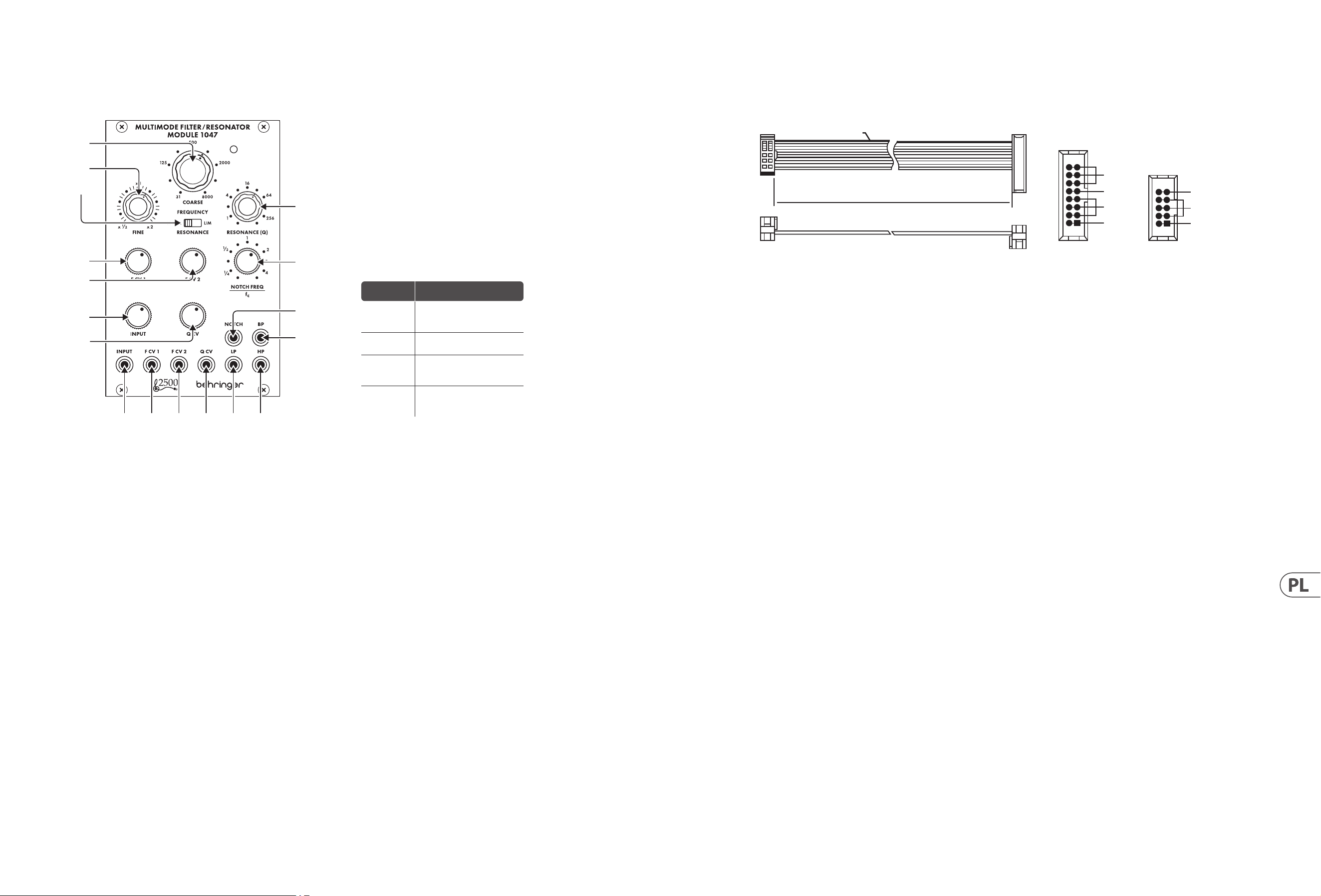
22 MULTIMODE FILTER / RESONATOR MODULE 1047 Quick Start Guide 23
MULTIMODE FILTER / RESONATOR MODULE 1047
Sterowanica
Podłączenie Zasilania
Moduł FILTRÓW / REZONATORÓW WIELOMODOWYCH 1047 jest dostarczany
zwymaganym kablem zasilającym do podłączenia do standardowego systemu
zasilania Eurorack. Wykonaj poniższe czynności, aby podłączyć zasilanie
domodułu. Łatwiej jest wykonać te połączenia przed zamontowaniem
modułuw obudowie rack.
1. Wyłącz zasilacz lub obudowę szafy i odłącz kabel zasilający.
2. Włóż 16-stykowe złącze przewodu zasilającego do gniazda w zasilaczu lub
wszae typu Rack. Złącze ma wypustkę, która będzie wyrównana ze szczeliną
w gnieździe, więcnie można jej nieprawidłowo włożyć. Jeśli zasilacz nie ma
gniazda z kluczem, należyzorientować styk 1 (-12 V) z czerwonym paskiem
nakablu.
3. Włóż 10-pinowe złącze do gniazda z tyłu modułu. Złącze ma wypustkę,
którabędzie wyrównana z gniazdem, aby zapewnić prawidłową orientację.
4. Po solidnym zamocowaniu obu końców kabla zasilającego można zamontować
moduł w obudowie i włączyć zasilacz.
Instalacja
Do modułu dołączone są niezbędne śruby do montażu w skrzynce Eurorack.
Podłącz kabel zasilający przed montażem.
W zależności od obudowy szafy może występować szereg stałych otworów
rozmieszczonych w odstępach 2 HP na całej długości obudowy lub prowadnica,
któraumożliwia przesuwanie pojedynczych gwintowanych płyt wzdłuż całej
obudowy. Swobodnie poruszające się gwintowane płytki umożliwiają precyzyjne
ustawienie modułu, ale każda płyta powinna być ustawiona w przybliżeniu w
stosunku do otworów montażowych w module przed przykręceniem śrub.
Przytrzymaj moduł na szynach Eurorack, tak aby każdy z otworów montażowych
był wyrównany z szyną gwintowaną lub płytą gwintowaną. Wkręć śruby
częściowo, aby rozpocząć, co pozwoli na drobne korekty położenia, gdywszystkie
zostaną wyrównane. Poustaleniu ostatecznej pozycji dokręcić śruby.
1. COARSE – Użyj tego pokrętła, aby wybrać obszar ogólnej częstotliwości,
który chcesz ustawić jako próg górnoprzepustowy, próg dolnoprzepustowy,
środkową częstotliwość pasmowoprzepustową i częstotliwość środkową
ltra wycinającego, a następnie przejdź do pokrętła FINE, aby udoskonalić
ustawienie częstotliwości. Częstotliwość ustawiona za pomocą pokręteł
COARSE i FINE („fc”) będzie używana jednocześnie dla każdego ltra
wmodule.
2. FINE – Użyj tego pokrętła do doprecyzowania i skupienia częstotliwości
ustawionej za pomocą pokrętła COARSE FREQUENCY.
3. RESONANCE (NORM/LIM) – Ten suwak umożliwia wybór między normalnym
trybem rezonansu (NORM) a trybem ograniczania (LIM), który ogranicza
wysokość szczytu rezonansowego ltra. Ustawienie LIM zapobiega przeciążeniu
obwodu podczas skupiania ltra na silnej częstotliwości harmonicznej
lub podstawowej, szczególnie przy wysokich ustawieniach Q na pokrętle
RESONANCE(Q). W innych sytuacjach ustawienie LIM może skutkować
bardzo niskim sygnałem wyjściowym, dlatego zwykle preferowane jest
ustawienieNORM.
4. RESONANCE (Q) – Pokrętło to kontroluje szerokość/gładkość i wąską/ostrość
krzywych ltra. Przy niskich ustawieniach Q krzywe ltra są szersze i gładsze,
z delikatniejszym wpływem na dźwięk (z wyjątkiem ltra wycinającego,
który działa najskuteczniej przy niskich ustawieniach Q). W miarę zwiększania
ustawienia Q krzywe ltra stopniowo stają się węższe i ostrzejsze, co może pomóc
w skupieniu się na wąskich pasmach częstotliwości. Przy wyższych ustawieniach
Q, różne ltry mogą wytwarzać szczyty rezonansowe na krzywych ltrów, które
wzmacniają niektóre częstotliwości i mogą wymagać przestawienia przełącznika
RESONANCE (NORM/LIM) na ustawienie LIM, aby zapobiec przeciążeniu obwodu
(lub można obrócić pokrętło tłumika INPUT na dół).
5. F CV 1 – Pokrętło to reguluje siłę sygnału napięcia sterującego wchodzącego
przez gniazdo F CV1.
6. F CV 2 – Pokrętło to reguluje siłę sygnału napięcia sterującego wchodzącego
przez gniazdo F CV2.
7. NOTCH FEQUENCY/fc – Użyj tego pokrętła, aby przesunąć środkową
częstotliwość ltra wycinającego („fc”) ustawioną za pomocą regulatorów
częstotliwości COARSE i FINE. Dla standardowego zachowania ltra
wycinającego, kontrolka NOTCH FREQ/fc powinna być ustawiona na „1” na
skali. To standardowe ustawienie można następnie dostosować, przesuwając
pokrętło NOTCH FREQ/fc bardzo nieznacznie wokół „1”. Ponadto, jeśli wyższe
wartości Q są dodawane za pomocą pokrętła RESONANCE, gdy ltr wycinający
jest przesunięty względem fc, wyższe wartości Q powodują powstanie piku
rezonansowego przy fc, z wycięciem w punkcie ustawionym pokrętłem
NOTCH FREQ/fc.
8. INPUT – Pokrętło to reguluje siłę sygnału audio przechodzącego przez
gniazdoINPUT.
9. Q CV – Pokrętło to reguluje siłę sygnału napięcia sterującego
Qprzychodzącego przez gniazdo Q CV.
10. INPUT – Użyj tego gniazda do kierowania sygnałów audio do modułu za
pomocą kabli ze złączami 3,5 mm. Możesz także skierować sygnał bramki
klawiatury, aby „dzwonił” ltr i wytworzył unikalny dźwięk perkusyjny po
naciśnięciu klawisza.
11. F CV 1 – Użyj tego gniazda, aby skierować zewnętrzne napięcie sterujące lub
sygnały modulacji dla ustawienia częstotliwości ltra do modułu za pomocą
kabli ze złączami 3,5 mm.
12. F CV 2 – Użyj tego gniazda, aby skierować zewnętrzne napięcie sterujące lub
sygnały modulacji dla ustawienia częstotliwości ltra do modułu za pomocą
kabli ze złączami 3,5 mm.
13. Q CV – Użyj tego gniazda, aby skierować zewnętrzne sygnały napięcia
sterującego dla ustawienia RESONANCE (Q) do modułu za pomocą kabli ze
złączami 3,5 mm.
14. LP – To gniazdo wysyła końcowy sygnał z ltra dolnoprzepustowego za
pomocą kabli ze złączami 3,5 mm.
15. HP – To gniazdo wysyła końcowy sygnał z ltra górnoprzepustowego za pomocą
kabli ze złączami 3,5 mm.
16. NOTCH – To gniazdo wysyła końcowy sygnał z ltra wycinającego za pomocą
kabli ze złączami 3,5 mm.
17. BP – To gniazdo wysyła końcowy sygnał z ltra pasmowego za pomocą kabli
ze złączami 3,5 mm.
HOT USED
Red Stripe
200 mm ± 10
15 16
21
P2P1
2
10 9
1
Connect end P1 to the module socket
Connect end P2 to the power supply
+ 12 V
- 12 V
GROUND
+ 12 V
- 12 V
GROUND
(1)
(2)
(3)
(4)
(5)
(6)
(7)
(8)
(9)
(10) (11) (12) (13) (14) (15)
(17)
(16)
Ustawienie
pokrętła
Efekt
Pełna CCW
Wyjście ltra wycinającego
staje się kopią wyjścia
górnoprzepustowego
W lewo
do ¼
Częstotliwość wycięcia zmienia
się znacznie poniżej fc
CW do 4
Częstotliwość wycięcia
przesuwa się znacznie
powyżej fc
Pełna CW
Wyjście ltra wycinającego
staje się kopią wyjścia ltra
dolnoprzepustowego
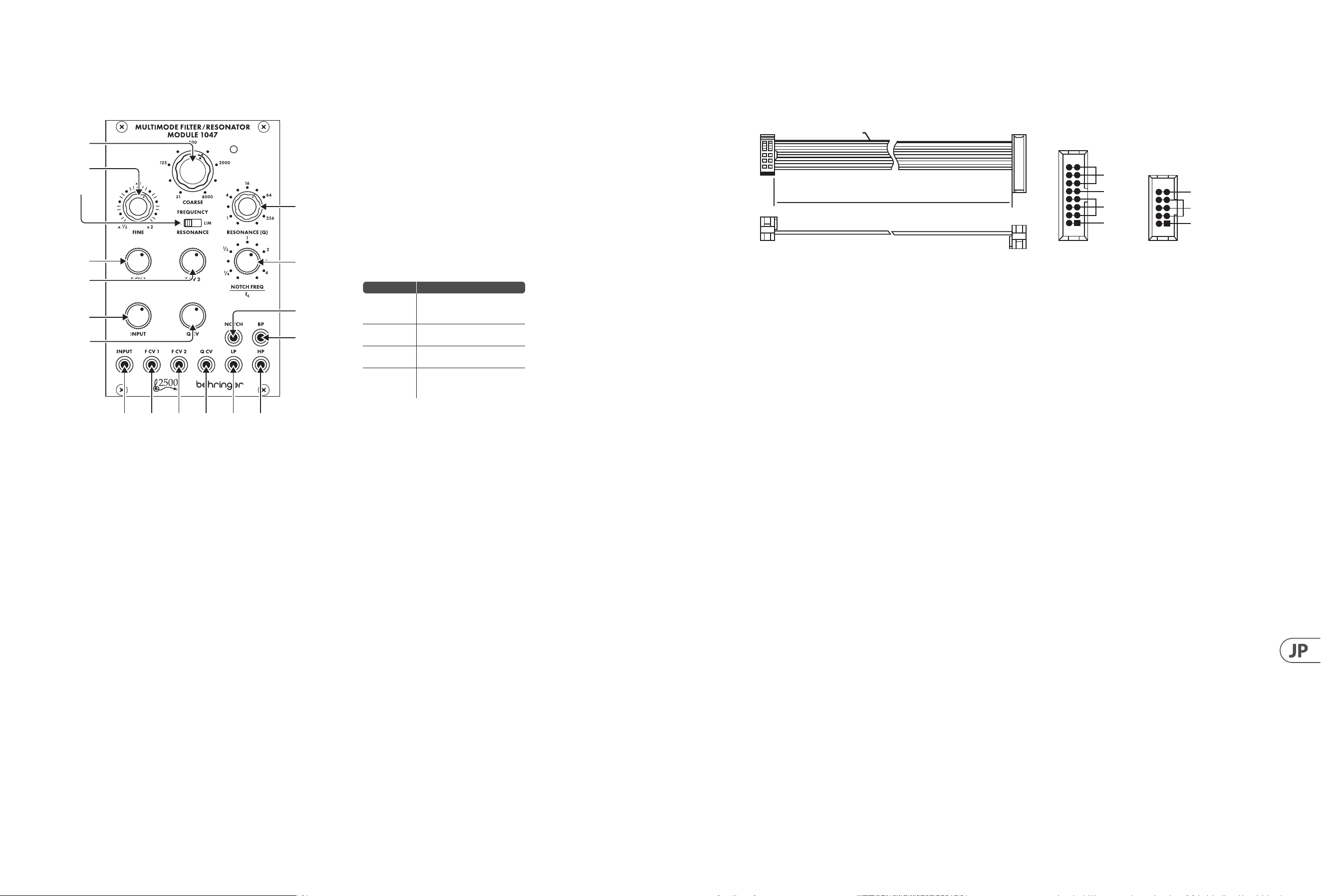
24 MULTIMODE FILTER / RESONATOR MODULE 1047 Quick Start Guide 25
MULTIMODE FILTER / RESONATOR MODULE 1047
コントロール
電源接続
MULTIMODE FILTER / RESONATOR MODULE 1047 モジュール には、標準の
Eurorack 電源システムに接続するために必要な電源ケーブルが
付属しています。次の手順に従って、モジュールに電源を接続し
ます。モジュールをラックケースに取り付ける前に、これらの接続
を行う方が簡単です。
1. 電源装置またはラックケースの電源を切り、電源ケーブルを外し
ます。
2. 電 源 ケーブル の 16 ピンコネクタを電源装置またはラックケース
のソケットに 挿入します。コ ネクタに はソケットの 隙 間 に合 うタ
ブが付いているので、間違って挿入することはできません。電源
装置にキー付きソケットがない場合は、必ずピン 1 (-12 V) をケー
ブル の 赤 い ストライプ に 向 け てください 。
3. モジュールの背面にあるソケットに 10 ピンコネクタを挿入し
ます。コネクタには、正しい方向に向けてソケットと位置合わせ
するタブが あります。
4. 電源ケーブルの両端をしっかりと取り付けたら、モジュールをケ
ースに 取り付け て 電 源 を入れ ます。
インストール
モジュールに含まれています。取り付ける前に電源ケーブルを接
続してください 。
ラックケ ースに よっては 、ケースの 長さに 沿 って 2 HP 間隔で配置
された一連の固定穴、または個々のネジ付きプレートをケースの
長さに 沿 ってスライド で きるトラックが 存 在 する 場 合 が ありま す。
自由に動くネジ付きプレートにより、モジュールを正確に配置でき
ますが、ネジを取り付ける前に、各プレートをモジュールの取り付
け穴とほぼ 同じ 位 置に 配 置する 必 要 が あります。
モジュール を Eurorack レールに押し付けて、各取り付け穴がネ
ジ付きレールまたはネジ付きプレートと揃うようにします。開始
の途中でネジを取り付けます。これにより、すべてのネジを揃えな
がら、位置を微調整できます。最終位置が決まったら、ネジを締
めます。
HOT USED
Red Stripe
200 mm ± 10
15 16
21
P2P1
2
10 9
1
Connect end P1 to the module socket
Connect end P2 to the power supply
+ 12 V
- 12 V
GROUND
+ 12 V
- 12 V
GROUND
1. COARSE – このノブ を 使 用して、ハイパ スしきい 値 、ロ ーパ スしき
い値、バンドパス中心周波数、およびノッチフィルターの中心周
波数に必要な一般的な周波数領域をダイヤルし、FINE ノブに移
動して周波数設定を調整します。COARSE ノブと FINE ノブで設定
さ れ た 周 波 数 (『 fc』)は、モジュール内のすべてのフィルターで同
時に使 用され ます。
2. FINE – このノブを使用して、COARSE FREQUENCY ノブで設 定された
周波数を調整してフォーカスします。
3. RESONANCE (NORM/LIM) – このスライドスイッチを使 用すると、
通常のレゾナンスモード (NORM) と、フィルターのレゾナントピ
ークの高さを制限する制限モード (LIM) のどちらかを選択でき
ます。LIM 設 定 は 、特 に RESONANCE (Q) ノブの高い Q 設 定 で 、強 い
高調波または基本周波数にフィルターを集中させるときに回路
の過負荷を防ぎます。他の状況では、LIM 設 定により出力信号が
非 常 に 低 く な る 可 能 性 が あ る た め 、通 常 は NORM 設定が推奨さ
れます。
4. RESONANCE (Q) – このノブは、フィルターカーブの幅 /滑らかさと
狭 さ / シ ャ ープ ネ ス を 制 御 し ま す 。低 Q 設 定 で は 、フ ィ ル タ ー カ ー
ブが広く滑らかになり、サウンドへの影響が穏やかになります
(低 Q 設定で最も効果的に機能するノッチフィルターを除く)。
Q 設 定を 大 きくすると、フィル ターカ ーブが 徐 々に 狭くなり、シャ
ープになります。これにより、狭い周波数帯域に焦点を合わせ
ることができます。より高い Q 設 定では、さまざまなフィルター
がフィルター曲線に共振ピークを生成し、一部の周波数をブー
ストする可能性があり、回路の過負荷を防ぐために RESONANCE
(NORM/ LIM) スイッチ を LIM 設 定に移 動する必 要があります
(または INPUT 減 衰器ノブを回すことができます) ダウン)。
5. F CV 1 – このノブは、F CV 1 ジャックから入ってくる制御電圧信号
の強度を調整します。
6. F CV 2 – このノブは、F CV 2 ジャックから入ってくる制御電圧信号
の強度を調整します。
7. NOTCH FEQUENCY/fc – このノブを使用して、COARSE および FINE 周波
数コントロールによって設定されたノッチフィルターの中心周
波数 (『fc』) をオフセットします。標 準 のノッチフィルター の 動
作では、NOTCH FREQ / fc コントロールをスケールで『1』 に設定す
る 必 要 が あ り ま す 。こ の 標 準 設 定 は 、NOTCH FREQ / fc ノブを 『1』
の周りでごくわずか に 動 かすことで 微 調 整 できます。また 、ノッ
チフィル ター が fc からオフセットされてい るときに RESONANCE
ノブ を 介して 高 い Q 値 が 追 加 さ れ る と 、高 い Q 値は fc に共振ピ
ー ク を も た ら し 、ノ ッ チ は NOTCH FREQ / fc ノブ に よって 設 定さ れ
ます。
8. INPUT – このノブは、INPUT ジャックを通過するオーディオ信号の
強度を調整します。
9. Q CV – このノブは、QCV ジャック か ら入ってくる Q 制御電圧信号
の強度を調整します。
10. INPUT – このジャックを使用して、3.5 mm コネクタ付 きの ケーブ
ルを介してオーディオ信号をモジュールにル ーティングします。
また、キーボードのゲート信号をル ーティングしてフィルター
を『鳴らし』、キーを押すと独特のパーカッシブなサウンドを生
成 することもできます。
11. F CV 1 – このジャックを使用して、フィルター周波数設定の外部
制御電圧または変調信号を、3.5 mm コネクタ付 きの ケーブル を
介してモジュールにルーティングします。
12. F CV 2 – このジャックを使用して、フィルター周波数設 定の外部
制御電圧または変調信号を、3.5 mm コネクタ付 きの ケーブル を
介してモジュールにルーティングします。
13. Q CV – このジャックを使用して、共振 (Q) 設定の外部制御電圧
信号を 3.5 mm コネクタ付きの ケーブル を 介してモジュール に ル
ー ティングします。
14. LP – このジャックは、3.5 mm コネクタ付 きの ケーブル を 介してロ
ーパ スフィル タか ら最 終 信 号 を 送 信しま す。
15. HP – このジャックは 、3.5 mm コネクタ付 きの ケーブル を介してハ
イパ スフィル タか ら最 終 信 号 を 送 信しま す。
16. NOTCH – このジャックは、3.5 mm コネクタ付 きの ケーブル を 介して
ノッチフィルタから最 終 信 号 を 送 信します。
17. BP – このジャックは 、3.5 mm コネクタ付きの ケーブル を 介してバ
ンドパ スフィル ターか ら最 終 信 号 を 送 信しま す。
(1)
(2)
(3)
(4)
(5)
(6)
(7)
(8)
(9)
(10) (11) (12) (13) (14) (15)
(17)
(16)
ノブの設定 効果
フル CCW
ノッチフィルター出力は、
ハイパス出力のコピーに
なります
CCW を ¼ に
ノッチ周波数が fc を大幅
に下回る
CW から 4
ノッチ周波数が fc を大幅
に上回っている
フル CW
ノッチフィルター出力は、
ローパスフィルター出力の
コピーになります
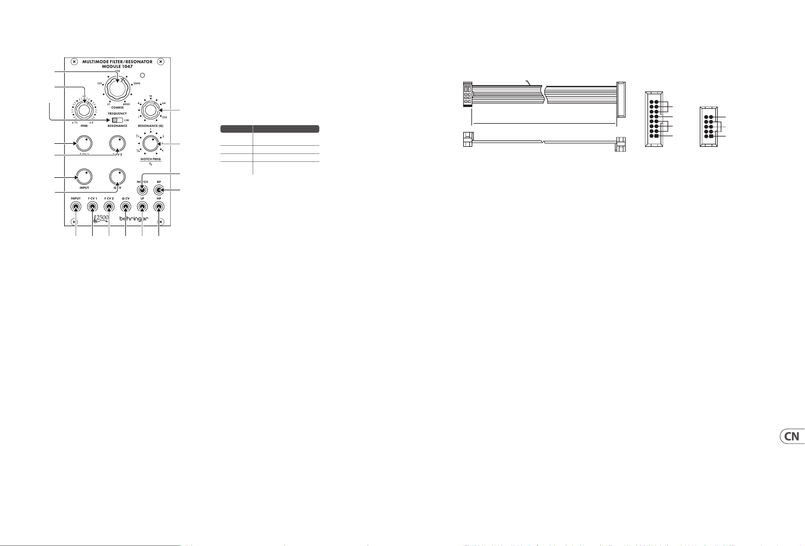
26 MULTIMODE FILTER / RESONATOR MODULE 1047 Quick Start Guide 27
MULTIMODE FILTER / RESONATOR MODULE 1047 控制
电源连接
305 EQ/MIXER/OUTPUT 模块随附用于连接到标准 Eurorack 电源系统的
所需电源线。 请按照以下步骤将电源连接到模块。 在将模块安装
到机架盒中之前, 进行这些连接会更容易。
1. 关闭电源或机架式机箱的电源, 然后断开电源线的连接。
2. 将电源线上的 16 针连接器插入电源或机架盒上的插座。 该连接
器具有一个卡舌, 该卡舌将与插槽中的间隙对齐, 因此不会被错
误地插入。 如果电源没有键控插座, 请确保将插针 1 (-12 V) 的方
向与电缆上的红色条纹对准。
3. 将 10 针连接器插入模块背面的插槽中。 连接器具有一个卡舌,
该卡舌将与插座对齐以正确定向。
4. 在牢固连接电源线的两端之后, 您可以将模块安装在盒中并打开
电源。
安装
模块随附了必要的螺钉, 用于将其安装在 Eurorack 箱中。 安装前,
请先连接电源线。
根据机架机箱的不同, 可能会有一系列沿机箱长度方向相距
2 HP 的固定孔, 或者是一条允许单个螺纹板沿机箱长度方向滑
动的导轨。 可以自由移动的螺纹板可以精确定位模块, 但是在安装
螺钉之前, 应将每个板的位置与模块上的安装孔大致成一定关系。
将模块靠在 Eurorack 导轨上, 以使每个安装孔都与螺纹导轨或螺
纹板对齐。 从头开始固定螺丝, 在对齐时可以对位置进行细微调
整。 确定最终位置后, 拧紧螺钉。
HOT USED
Red Stripe
200 mm ± 10
15 16
21
P2P1
2
10 9
1
Connect end P1 to the module socket
Connect end P2 to the power supply
+ 12 V
- 12 V
GROUND
+ 12 V
- 12 V
GROUND
1. COARSE – 使用此旋钮拨入您想要的高通阈值, 低通阈值, 带通中
心频率和陷波器中心频率的一般频率区域, 然后转到
FINE
旋钮以
细化频率设置。 由
COARSE
和
FINE
旋钮 (“
fc
”) 设置的频率将同时用
于模块中的每个滤波器。
2. FINE – 使用此旋钮可以细化和聚焦由 COARSE FREQUENCY 旋钮设置
的频率。
3. RESONANCE (NORM/LIM) – 此滑动开关可让您在正常谐振模式
(NORM) 和限制模式 (LIM) 之间进行选择, 后者限制了滤波器谐振
峰值的高度。 当滤波器聚焦于强谐波或基频时, LIM 设置可防止
电路过载, 尤其是在 RESONANCE (Q) 旋钮上的高 Q 设置时。 在其
他情况下, LIM 设置会导致输出信号非常低, 因此通常首选 NORM
设置。
4. RESONANCE (Q) – 此旋钮控制滤波器曲线的宽度/平滑度和窄度/
锐度。 在低 Q 设置下, 滤波器曲线更宽、更平滑, 对声音的影响更
柔和 (陷波滤波器除外, 它在低 Q 设置下最有效)。 随着 Q 设置的
增加, 滤波器曲线逐渐变窄和锐利, 这可以帮助您专注于较窄的
频段。 在较高 Q 设置下, 各种滤波器会在滤波器曲线中产生谐振
峰值, 从而提升某些频率, 并且可能需要将 RESONANCE (NORM/LIM)
开关移至 LIM 设置以防止电路过载(或可以转动 INPUT 衰减器旋
钮下)。
5. F CV 1 – 该旋钮调节通过 F CV 1 插孔输入的控制电压信号的强度。
6. F CV 2 – 该旋钮调节通过 F CV 2 插孔输入的控制电压信号的强度。
7. NOTCH FEQUENCY/fc – 使用此旋钮偏移由 COARSE 和 FINE 频率控件
设置的陷波滤波器的中心频率 (“fc”)。 对于标准陷波滤波器行为,
NOTCH FREQ/fc 控件应在刻度上设置为”1”。 然后可以通过在”1”附近
稍微移动 NOTCH FREQ/fc 旋钮来调整此标准设置。 此外, 如果在陷
波滤波器偏离 fc 时通过 RESONANCE 旋钮添加更高的 Q 值, 则更高
的 Q 值会在 fc 处产生谐振峰值, 陷波位于由 NOTCH FREQ/fc 旋钮设
置的点。
8. INPUT – 此旋钮可调节通过 INPUT 插孔传入的音频信号的强度。
9. Q CV – 该旋钮调节通过 Q CV 插孔输入的 Q 控制电压信号的强度。
10. INPUT – 使用此插孔通过带有 3.5 毫米连接器的电缆将音频信号
路由到模块中。 您还可以将键盘门限信号路由到”振铃”滤波器并
在您按下琴键时产生独特的打击乐声音。
11. F CV 1 – 使用此插孔可通过带有 3.5 毫米连接器的电缆将用于滤
波器频率设置的外部控制电压或调制信号路由到模块中。
12. F CV 2 – 使用此插孔可通过带有 3.5 毫米连接器的电缆将用于滤
波器频率设置的外部控制电压或调制信号路由到模块中。
13. Q CV – 使用此插孔通过带有 3.5 mm 连接器的电缆将用于
RESONANCE (Q) 设置的外部控制电压信号路由到模块中。
14. LP – 该插孔通过带有 3.5 毫米连接器的电缆从低通滤波器发出
最终信号。
15. HP – 该插孔通过带有 3.5 毫米连接器的电缆从高通滤波器发出
最终信号。
16. NOTCH – 该插孔通过带有 3.5 毫米连接器的电缆从陷波滤波器发
出最终信号。
17. BP – 该插孔通过带 3.5 毫米连接器的电缆从带通滤波器发出最
终信号。
(1)
(2)
(3)
(4)
(5)
(6)
(7)
(8)
(9)
(10) (11) (12) (13) (14) (15)
(17)
(16)
旋钮设置
Eect
满的 CCW
陷波滤波器输出成为高通输
出的副本
CCW 至 ¼ 陷波频率明显低于 fc
CW 至 4 陷波频率明显高于 fc
满的 CW
陷波滤波器输出成为低通滤
波器输出的副本
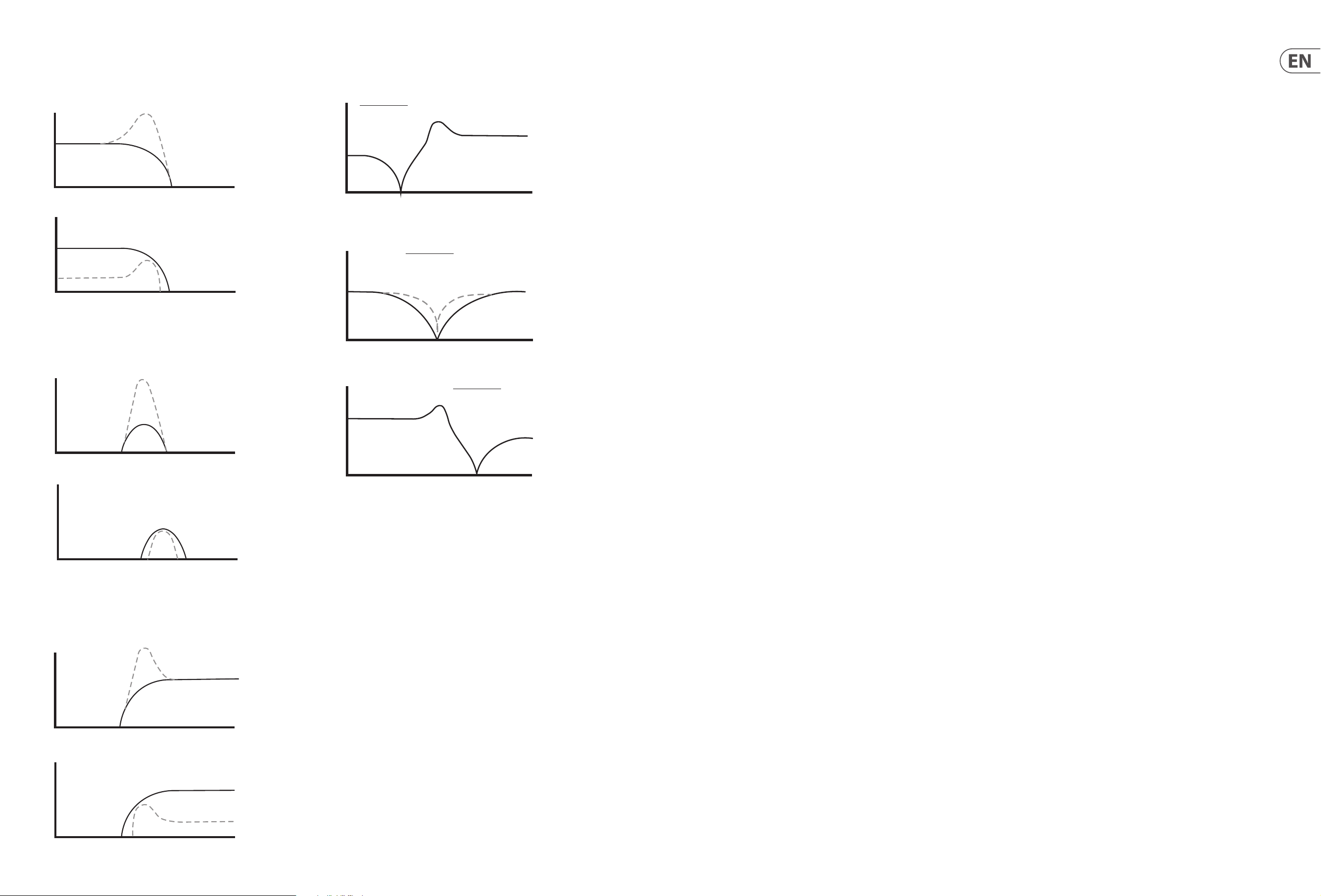
28 MULTIMODE FILTER / RESONATOR MODULE 1047 Quick Start Guide 29
Q=2
NORMAL MODE
LOWPASS RESPONSE
Q=½
16 Hz
16 KHzFc
16 Hz
16 KHzFc
Q=2
LIMIT MODE
Q=½
16 Hz 16 KHzFc
16 Hz
16 KHz
Fc
Q=2
NORMAL MODE
BANDPASS RESPONSE
Q=½
Q=2
LIMIT MODE
Q=½
16 Hz
16 KHzFc
16 Hz 16 KHzFc
Q=2
NORMAL MODE
HIGHPASS RESPONSE
Q=½
Q=2
LIMIT MODE Q=½
Notch Responses
Fc/4 4FcFc
Q=2
Fc
NOTCH FREQ
= ¼
Q=½ Q=½
Fc/4 4FcFc
Q=2
Fc
NOTCH FREQ
= 1
Fc/4 4FcFc
Q=2
Fc
NOTCH FREQ
= 4
Filter Curves
30 MULTIMODE FILTER / RESONATOR MODULE 1047 Quick Start Guide 31
Specications
技术参数
Inputs
Input
Type 1 x 3.5 mm TS jack, DC coupled
Impedance 50 kΩ, unbalanced
Max input level +18 dBu
Frequency CV input 1
Type 1 x 3.5 mm TS jack, DC coupled
Impedance 50 kΩ, unbalanced
Max input level ±10 V
CV scaling 1 V/oct.
Frequency CV input 2
Type 1 x 3.5 mm TS jack, DC coupled
Impedance 50 kΩ, unbalanced
Max input level ±10 V
CV scaling 1 V/oct.
Q CV input
Type 1 x 3.5 mm TS jack, DC coupled
Impedance 50 kΩ, unbalanced
Max input level ±10 V
CV scaling 1 V doubles the Q factor
Outputs
Filter outputs (LP / HP / BP / Notch)
Type 4 x 3.5 mm TS jack, DC coupled
Impedance 1 kΩ, unbalanced
Max output level +18 dBu
Controls
Coarse frequency 1 x rotary knob, 31 Hz to 8 kHz
Fine frequency 1 x rotary knob, x1/2 to x2
Resonance (Q) 1 rotary knob, Q = 0.5 to >256
Resonance (Norm / lim)
2-way sliding switch
Normal / limiting, switchable
Frequency CV 1 / 2 attenuators 2 x rotary knob, -∞ to unity gain
Q CV attenuator 1 x rotary knob, -∞ to unity gain
Input attenuator 1 x rotary knob, -∞ to unity gain
Notch frequency/fc 1 x rotary knob, ±3 octave range
Power
Power supply Eurorack
Current draw 55 mA (+12 V), 45 mA (-12 V)
Physical
Dimensions 43 x 81 x 129 mm (1.7 x 3.2 x 5.1")
Rack units 16 HP
Weight 0.17 kg (0.37 lbs)
输入
输入
类型
1 x 3.5 mm TS 1 x 3.5 mm TS 插孔, 直流耦合
阻抗
50 kΩ, 不平衡
最大输入电平
+18 dBu
频率 CV 输入 1
类型
1 x 3.5 mm TS 1 x 3.5 mm TS 插孔, 直流耦合
阻抗
50 kΩ, 不平衡
最大输入电平
±10 V
简历缩放
1 V/oct.
频率 CV 输入 2
类型
1 x 3.5 mm TS 1 x 3.5 mm TS 插孔, 直流耦合
阻抗
50 kΩ, 不平衡
最大输入电平
±10 V
简历缩放
1 V/oct.
Q 简历输入
类型
1 x 3.5 mm TS 1 x 3.5 mm TS 插孔, 直流耦合
阻抗
50 kΩ, 不平衡
最大输入电平
±10 V
简历缩放
1 V 使 Q 因子加倍
输出
滤波器输出 (LP / HP / BP / Notch)
类型
4 x 3.5 mm TS 1 x 3.5 mm TS 插孔, 直流耦合
阻抗
1 kΩ, 不平衡
最大输出电平
+18 dBu
控件
粗频率
1 x 旋钮, 31 Hz 至 8 kHz
精细频率
1 x 旋钮, x 1/2 至 x2
谐振 (Q) 1 个旋钮, Q = 0.5 至 >256
共振 (Norm / lim)
2 路滑动开关 正常/限位,
可切换
频率 CV 1 / 2 衰减器 2 x 旋钮, -∞ 为单位增益
Q CV 衰减器 1 x 旋钮, -∞ 为单位增益
输入衰减器
1 x 旋钮, -∞ 为单位增益
陷波频率/fc
1 x 旋钮, ±3 倍频程范围
力量
电源供应 欧洲机架
当前平局
55 mA (+12 V), 45 mA (-12 V)
身体的
方面
43 x 81 x 129 mm (1.7 x 3.2 x 5.1")
机架单元
16 HP
重量
0.17 kg (0.37 lbs)
32 MULTIMODE FILTER / RESONATOR MODULE 1047 Quick Start Guide 33
FEDERAL COMMUNICATIONS
COMMISSION COMPLIANCE
INFORMATION
Responsible Party Name: Music Tribe Commercial NV Inc.
Address: 122 E. 42nd St.1,
8th Floor NY, NY 10168,
United States
Email Address: legal@musictribe.com
This equipment has been tested and found to comply with the limits for a Class B
digital device, pursuant to part 15 of the FCC Rules. These limits are designed
to provide reasonable protection against harmful interference in a residential
installation. This equipment generates, uses and can radiate radio frequency
energy and, if not installed and used in accordance with the instructions, may cause
harmful interference to radio communications. However, there is no guarantee that
interference will not occur in a particular installation. If this equipment does cause
harmful interference to radio or television reception, which can be determined
by turning the equipment o and on, the user is encouraged to try to correct the
interference by one or more of the following measures:
• • Reorient or relocate the receiving antenna.
• • Increase the separation between the equipment and receiver.
• • Connect the equipment into an outlet on a circuit dierent from that to which the
receiver is connected.
• • Consult the dealer or an experienced radio/TV technician for help.
This equipment complies with Part 15 of the FCC rules. Operation is subject to the
following two conditions:
(1) this device may not cause harmful interference, and
(2) this device must accept any interference received, including interference that may
cause undesired operation.
Important information:
Changes or modications to the equipment not expressly approved by Music Tribe
can void the user’s authority to use the equipment.
Hereby, Music Tribe declares that this product is in compliance with General Product
Safety Regulation (EU) 2023/988, Directive 2014/30/EU, Directive 2011/65/EU and
Amendment 2015/863/EU, Directive 2012/19/EU, Regulation 519/2012 REACH SVHC
and Directive 1907/2006/EC.
Full text of EU DoC is available at https://community.musictribe.com/
EU Representative: Music Tribe Brands DK A/S
Address: Gammel Strand 44, DK-1202 København K, Denmark
UK Representative: Music Tribe Brands UK Ltd.
Address: 8
th
Floor, 20 Farringdon Street London EC4A 4AB, United Kingdom
Correct disposal of this product: This symbol indicates that this
product must not be disposed of with household waste,
according to the WEEE Directive (2012/19/EU) and your
national law. This product should be taken to a collection
center licensed for the recycling of waste electrical and
electronic equipment (EEE). The mishandling of this type of
waste could have a possible negative impact on the
environment and human health due to potentially hazardous
substances that are generally associated with EEE. At the same
time, your cooperation in the correct disposal of this product will contribute to the
ecient use of natural resources. For more information about where you can take
your waste equipment for recycling, please contact your local city oce, or your
household waste collection service.
型号: MULTIMODE FILTER / RESONATOR MODULE 1047
合成器与采样器
制造商: Empower Tribe Commercial FZE
Made in China 中国制造
CAN ICES–003 (B)/NMB–003 (B)
Behringer
MULTIMODE FILTER / RESONATOR MODULE 1047
MULTIMODE FILTER / RESONATOR MODULE 1047

We Hear You
