Quick Start Guide
SURGES
“Liquid” Multi-Mode Filter
for Eurorack
V 1.0
(EN) Safety Instruction
1. Please read and follow all instructions.
2. Keep the apparatus away from water, except for
outdoor products.
3. Clean only with a dry cloth.
4. Do not block any ventilation openings. Install in
accordance with the manufacturer’s instructions.
5. Do not install near any heat sources such as radiators,
heat registers, stoves or other apparatus (including
ampliers) that produce heat.
6. Use only attachments/accessories specied by the
manufacturer.
7. Use only specied carts, stands,
tripods, brackets, or tables. Use caution to
prevent tip-over when moving the cart/
apparatus combination.
8. Avoid installing in conned spaces like bookcases.
9. Do not place near naked ame sources,
such as lighted candles.
10. Operating temperature range 5° to 45°C
(41° to 113°F).
LEGAL DISCLAIMER
Music Tribe accepts no liability for any loss which may
be suered by any person who relies either wholly or in
part upon any description, photograph, or statement
contained herein. Technical specications, appearances
and other information are subject to change without
notice. All trademarks are the property of their respective
owners. Midas, Klark Teknik, Lab Gruppen, Lake, Tannoy,
Turbosound, TC Electronic, TC Helicon, Behringer, Bugera,
Aston Microphones and Coolaudio are trademarks or
registered trademarks of Music Tribe Global Brands Ltd.
© Music Tribe Global Brands Ltd. 2024 All rights reserved.
LIMITED WARRANTY
For the applicable warranty terms and conditions and
additional information regarding Music Tribe’s Limited
Warranty, please see complete details online at community.
musictribe.com/pages/support#warranty.
(ES) Instrucción de seguridad
1. Por favor, lea y siga todas las instrucciones.
2. Mantenga el aparato alejado del agua, excepto para
productos destinados al uso en exteriores.
3. Limpie solo con un paño seco.
4. No bloquee ninguna abertura de ventilación.
Instale de acuerdo con las instrucciones del fabricante.
5. No instale cerca de fuentes de calor como radiadores,
registros de calor, estufas u otros aparatos (incluyendo
amplicadores) que generen calor.
6. Utilice solo accesorios especicados por el fabricante.
7. Use solo carros, soportes, trípodes,
soportes o mesas especicados. Tenga
precaución para evitar el vuelco al mover la
combinación carro/aparato.
8. Evite la instalación en espacios connados
como estanterías.
9. No colocar cerca de fuentes de llama desnuda,
como velas encendidas.
10. Rango de temperatura de funcionamiento de
5° a 45°C (41° a 113° F).
NEGACIÓN LEGAL
Music Tribe no admite ningún tipo de responsabilidad
por cualquier daño o pérdida que pudiera sufrir
cualquier persona por conar total o parcialmente en la
descripciones, fotografías o armaciones contenidas en
este documento. Las especicaciones técnicas, imágenes
y otras informaciones contenidas en este documento
están sujetas a modicaciones sin previo aviso. Todas las
marcas comerciales que aparecen aquí son propiedad de
sus respectivos dueños. Midas, Klark Teknik, Lab Gruppen,
Lake, Tannoy, Turbosound, TC Electronic, TC Helicon,
Behringer, Bugera, Aston Microphones y Coolaudio son
marcas comerciales o marcas registradas de Music Tribe
Global Brands Ltd. © Music Tribe Global Brands Ltd.
2024 Reservados todos los derechos.
GARANTÍA LIMITADA
Si quiere conocer los detalles y condiciones aplicables
de la garantía así como información adicional sobre la
Garantía limitada de Music Tribe, consulte online toda la
información en la web community.musictribe.com/pages/
support#warranty.
3Quick Start Guide2 SURGES
(FR) Consignes de sécurité
1. Veuillez lire et suivre toutes les instructions.
2. Gardez l'appareil éloigné de l'eau, sauf pour les
produits destinés à une utilisation en extérieur.
3. Nettoyez uniquement avec un chion sec.
4. Ne bloquez aucune ouverture de ventilation.
Installez conformément aux instructions du fabricant.
5. N'installez pas près de sources de chaleur telles que
radiateurs, grilles de chaleur, cuisinières ou autres appareils
(y compris les amplicateurs) qui produisent de la chaleur.
6. Utilisez uniquement les accessoires spéciés
par le fabricant.
7. Utilisez uniquement des chariots, des
supports, des trépieds, des supports ou des
tables spéciés. Faites attention pour éviter
le renversement lors du déplacement de la
combinaison chariot/appareil.
8. Évitez l'installation dans des espaces connés comme
les bibliothèques.
9. Ne pas placer près de sources de amme nue, telles
que des bougies allumées.
10. Plage de température de fonctionnement de
5° à 45°C (41° à 113°F).
DÉNI LÉGAL
Music Tribe ne peut être tenu pour responsable pour
toute perte pouvant être subie par toute personne
se ant en partie ou en totalité à toute description,
photographie ou armation contenue dans ce document.
Les caractéristiques, l’apparence et d’autres informations
peuvent faire l’objet de modications sans notication.
Toutes les marques appartiennent à leurs propriétaires
respectifs. Midas, Klark Teknik, Lab Gruppen, Lake, Tannoy,
Turbosound, TC Electronic, TC Helicon, Behringer, Bugera,
Aston Microphones et Coolaudio sont des marques ou
marques déposées de Music Tribe Global Brands Ltd. ©
Music Tribe Global Brands Ltd. 2024 Tous droits réservés.
GARANTIE LIMITÉE
Pour connaître les termes et conditions de garantie
applicables, ainsi que les informations supplémentaires et
détaillées sur la Garantie Limitée de Music Tribe, consultez
le site Internet community.musictribe.com/pages/
support#warranty.
(DE) Wichtige Sicherheitshinweise
1. Bitte lesen Sie alle Anweisungen sorgfältig durch und
befolgen Sie diese.
2. Halten Sie das Gerät von Wasser fern, außer für
Produkte, die für den Außeneinsatz vorgesehen sind.
3. Reinigen Sie es nur mit einem trockenen Tuch.
4. Blockieren Sie keine Belüftungsönungen. Installieren
Sie gemäß den Anweisungen des Herstellers.
5. Installieren Sie nicht in der Nähe von Wärmequellen
wie Heizkörpern, Heizregistern, Öfen oder anderen Geräten
(einschließlich Verstärkern), die Wärme erzeugen.
6. Verwenden Sie nur Zubehörteile, die vom Hersteller
angegeben sind.
7. Verwenden Sie nur spezizierte
Wagen, Ständer, Stative, Halterungen oder
Tische. Achten Sie darauf, beim Bewegen
der Wagen-Geräte-Kombination ein
Umkippen zu vermeiden.
8. Vermeiden Sie die Installation in beengten Räumen
wie Bücherregalen.
9. Nicht in der Nähe von oenen Flammenquellen
platzieren, wie brennende Kerzen.
10. Betriebstem-peraturbereich von 5° bis 45°C
(41° bis 113°F).
HAFTUNGSAUSSCHLUSS
Music Tribe übernimmt keine Haftung für Verluste, die
Personen entstanden sind, die sich ganz oder teilweise
auf hier enthaltene Beschreibungen, Fotos oder Aussagen
verlassen haben. Technische Daten, Erscheinungsbild
und andere Informationen können ohne vorherige
Ankündigung geändert werden. Alle Warenzeichen sind
Eigentum der jeweiligen Inhaber. Midas, Klark Teknik,
Lab Gruppen, Lake, Tannoy, Turbosound, TC Electronic,
TC Helicon, Behringer, Bugera, Aston Microphones
und Coolaudio sind Warenzeichen oder eingetragene
Warenzeichen der Music Tribe Global Brands Ltd. © Music
Tribe Global Brands Ltd. 2024 Alle Rechte vorbehalten.
BESCHRÄNKTE GARANTIE
Die geltenden Garantiebedingungen und zusätzliche
Informationen bezüglich der von Music Tribe gewährten
beschränkten Garantie nden Sie online unter community.
musictribe.com/pages/support#warranty.
5Quick Start Guide4 SURGES
(PT) Instruções de Seguranç
Importantes
1. Por favor, leia e siga todas as instruções.
2. Mantenha o aparelho longe da água, exceto para
produtos destinados ao uso externo.
3. Limpe apenas com um pano seco.
4. Não bloqueie nenhuma abertura de ventilação.
Instale de acordo com as instruções do fabricante.
5. Não instale próximo a fontes de calor, como
radiadores, grelhas de calor, fogões ou outros aparelhos
(incluindo amplicadores) que gerem calor.
6. Use apenas acessórios especicados pelo fabricante.
7. Use apenas carrinhos, suportes, tripés,
suportes ou mesas especicados. Tenha
cuidado para evitar tombamentos ao mover
a combinação carrinho/aparelho.
8. Evite instalar em espaços connados, como estantes.
9. Não coloque perto de fontes de chama nua, como
velas acesas.
10. Intervalo de temperatura de operação de
5° a 45°C (41° a 113° F).
LEGAL RENUNCIANTE
O Music Tribe não se responsabiliza por perda alguma
que possa ser sofrida por qualquer pessoa que dependa,
seja de maneira completa ou parcial, de qualquer
descrição, fotograa, ou declaração aqui contidas. Dados
técnicos, aparências e outras informações estão sujeitas
a modicações sem aviso prévio. Todas as marcas são
propriedade de seus respectivos donos. Midas, Klark Teknik,
Lab Gruppen, Lake, Tannoy, Turbosound, TC Electronic,
TC Helicon, Behringer, Bugera, Aston Microphones e
Coolaudio são marcas ou marcas registradas do Music Tribe
Global Brands Ltd. © Music Tribe Global Brands Ltd. 2024
Todos direitos reservados.
GARANTIA LIMITADA
Para obter os termos de garantia aplicáveis e
condições e informações adicionais a respeito
da garantia limitada do Music Tribe, favor
vericar detalhes na íntegra através do website
community.musictribe.com/pages/support#warranty.
(IT) Istruzioni di sicurezza importanti
1. Per favore, leggere e seguire tutte le istruzioni.
2. Mantenere l'apparecchio lontano dall'acqua,
tranne per i prodotti destinati all'uso all'aperto.
3. Pulire solo con un panno asciutto.
4. Non ostruire alcuna apertura di ventilazione.
Installare in conformità alle istruzioni del produttore.
5. Non installare vicino a fonti di calore come
termosifoni, bocchette di calore, fornelli o altri apparecchi
(compresi gli amplicatori) che producono calore.
6. Utilizzare solo accessori specicati dal produttore.
7. Usare solo carrelli, supporti,
treppiedi, stae o tavoli specicati.
Prestare attenzione per evitare il
ribaltamento durante lo spostamento della
combinazione carrello/apparecchio.
8. Evitare l'installazione in spazi connati come librerie.
9. Non posizionare vicino a fonti di amma nude, come
candele accese.
10. Intervallo di temperatura di funzionamento da
5° a 45°C (41° a 113°F).
DISCLAIMER LEGALE
Music Tribe non si assume alcuna responsabilità per
eventuali danni che possono essere subiti da chiunque si
adi in tutto o in parte a qualsiasi descrizione, fotograa
o dichiarazione contenuta qui. Speciche tecniche, aspetti
e altre informazioni sono soggette a modiche senza
preavviso. Tutti i marchi sono di proprietà dei rispettivi
titolari. Midas, Klark Teknik, Lab Gruppen, Lake, Tannoy,
Turbosound, TC Electronic, TC Helicon, Behringer, Bugera,
Aston Microphones e Coolaudio sono marchi o marchi
registrati di Music Tribe Global Brands Ltd. © Music Tribe
Global Brands Ltd. 2024 Tutti i diritti riservati.
GARANZIA LIMITATA
Per i termini e le condizioni di garanzia applicabili e le
informazioni aggiuntive relative alla garanzia limitata
di Music Tribe, consultare online i dettagli completi su
community.musictribe.com/pages/support#warranty.
7Quick Start Guide6 SURGES
(NL) Belangrijke
veiligheidsvoorschriften
1. Lees alsjeblieft alle instructies en volg deze op.
2. Houd het apparaat uit de buurt van water, behalve
voor producten die bedoeld zijn voor buitengebruik.
3. Reinig alleen met een droge doek.
4. Blokker geen ventilatieopeningen. Installeer volgens
de instructies van de fabrikant.
5. Installeer niet in de buurt van warmtebronnen
zoals radiatoren, warmte registers, fornuizen of andere
apparaten (inclusief versterkers) die warmte produceren.
6. Gebruik alleen accessoires die door de fabrikant
zijn gespeciceerd.
7. Gebruik alleen gespeciceerde
karren, standaards, statieven, beugels of
tafels. Wees voorzichtig om kantelen te
voorkomen bij het verplaatsen van de kar/
apparaatcombinatie.
8. Vermijd installatie in afgesloten ruimtes zoals
boekenkasten.
9. Plaats niet in de buurt van naakte vlambronnen,
zoals brandende kaarsen.
10. Bedrijfstem-peratuurbereik van 5° tot 45°C
(41° tot 113°F).
WETTELIJKE ONTKENNING
Music Tribe aanvaardt geen aansprakelijkheid voor enig
verlies dat kan worden geleden door een persoon die
geheel of gedeeltelijk vertrouwt op enige beschrijving, foto
of verklaring hierin. Technische specicaties, verschijningen
en andere informatie kunnen zonder voorafgaande
kennisgeving worden gewijzigd. Alle handelsmerken zijn
eigendom van hun respectievelijke eigenaren. Midas,
Klark Teknik, Lab Gruppen, Lake, Tannoy, Turbosound,
TC Electronic, TC Helicon, Behringer, Bugera, Aston
Microphones en Coolaudio zijn handelsmerken of
gedeponeerde handelsmerken van Music Tribe Global
Brands Ltd. © Music Tribe Global Brands Ltd. 2024 Alle
rechten voorbehouden.
BEPERKTE GARANTIE
Voor de toepasselijke garantievoorwaarden en aanvullende
informatie met betrekking tot de beperkte garantie van
Music Tribe, zie de volledige details online op community.
musictribe.com/pages/support#warranty.
(SE) Viktiga säkerhetsanvisningar
1. Vänligen läs och följ alla instruktioner noggrant.
2. Håll apparaten borta från vatten, förutom för
utomhusprodukter.
3. Rengör endast med en torr trasa.
4. Blockera inte några ventilationsöppningar.
Installera enligt tillverkarens anvisningar.
5. Installera inte nära några värmekällor som element,
värmeregistrar, spisar eller andra apparater (inklusive
förstärkare) som genererar värme.
6. Använd endast tillbehör som anges av tillverkaren.
7. Använd endast specicerade vagnar,
ställ, stativ, fästen eller bord. Var försiktig
för att undvika att vagnen/
apparatkombinationen tippar
när den yttas.
8. Undvik installation i trånga utrymmen som bokhyllor.
9. Placera inte nära öppen låga, såsom tända ljus.
10. Driftstem-peraturområde 5° till 45°C (41° till 113°F).
FRISKRIVNINGSKLAUSUL
Music Tribe tar inget ansvar för någon förlust som kan
drabbas av någon person som helt eller delvis förlitar sig på
någon beskrivning, fotogra eller uttalande som nns här.
Tekniska specikationer, utseenden och annan information
kan ändras utan föregående meddelande. Alla varumärken
tillhör respektive ägare. Midas, Klark Teknik, Lab Gruppen,
Lake, Tannoy, Turbosound, TC Electronic, TC Helicon,
Behringer, Bugera, Aston Microphones och Coolaudio är
varumärken eller registrerade varumärken som tillhör
Music Tribe Global Brands Ltd. © Music Tribe Global Brands
Ltd. 2024 Alla Rättigheter reserverade.
BEGRÄNSAD GARANTI
För tillämpliga garantivillkor och ytterligare information
om Music Tribes begränsade garanti, se fullständig
information online på community.musictribe.com/pages/
support#warranty.
9Quick Start Guide8 SURGES
(PL) Ważne informacje o
bezpieczeństwie
1. Proszę przeczytać i ścisłe przestrzegać
wszystkich instrukcji.
2. Trzymaj urządzenie z dala od wody, z wyjątkiem
produktów przeznaczonych do użytku na zewnątrz.
3. Czyść tylko suchą szmatką.
4. Nie blokuj żadnych otworów wentylacyjnych.
Instaluj zgodnie z instrukcjami producenta.
5. Nie instaluj w pobliżu źródeł ciepła, takich jak
grzejniki, rejestratory ciepła, kuchenki lub inne urządzenia
(w tym wzmacniacze), które generują ciepło.
6. Używaj tylko akcesoriów określonych
przez producenta.
7. Używaj tylko określonych wózków,
stojaków, statywów, uchwytów lub stołów.
Uważaj, aby zapobiec przewróceniu się
wózka/aparatu podczas przemieszczania.
8. Unikaj instalacji w ciasnych miejscach, takich jak
regały na książki.
9. Nie umieszczaj w pobliżu źródeł otwartego ognia,
takich jak zapalone świeczki.
10. Zakres temperatury pracy od 5° do 45°C (41° do 113°F).
ZASTRZEŻENIA PRAWNE
Music Tribe nie ponosi odpowiedzialności za jakiekolwiek
straty, które mogą ponieść osoby, które polegają w
całości lub w części na jakimkolwiek opisie, fotograi
lub oświadczeniu zawartym w niniejszym dokumencie.
Specykacje techniczne, wygląd i inne informacje mogą
ulec zmianie bez powiadomienia. Wszystkie znaki
towarowe są własnością ich odpowiednich właścicieli.
Midas, Klark Teknik, Lab Gruppen, Lake, Tannoy,
Turbosound, TC Electronic, TC Helicon, Behringer, Bugera,
Aston Microphones i Coolaudio są znakami towarowymi
lub zastrzeżonymi znakami towarowymi rmy Music Tribe
Global Brands Ltd. © Music Tribe Global Brands Ltd.
2024 Wszystkie prawa zastrzeżone.
OGRANICZONA GWARANCJA
Aby zapoznać się z obowiązującymi warunkami gwarancji
i dodatkowymi informacjami dotyczącymi ograniczonej
gwarancji Music Tribe, zapoznaj się ze wszystkimi
szczegółami w trybie online pod adresem community.
musictribe.com/pages/support#warranty.
(JP) 安全指示
1. すべての指示を読んで、従ってください。
2. 屋外の製品を除き、機器を水から遠ざけ
てください。
3. 乾いた布でのみ清掃してください。
4. 通気口を塞がないでください。メーカーの
指示に従ってインストールしてください。
5. 暖房器、ヒートレジスター、ストーブなど
の発熱機器(アンプを含む)の近くには取り付
けないでください。
6. メーカーが指定したアタッチメント/アク
セサリーのみ使用してください。
7. 指定されたカート、スタン
ド、三脚、ブラケット、またはテ
ーブルのみ使用してください。
カート/機器の組み合わせを移動す
る際には、転倒を防ぐよう注意してください。
8. 書棚などの密閉された空間には設置しない
でください。
9. 裸火のような火の元の近くに置かないで
ください。
10.
動作温度範囲は摂氏 5 度から 45 度
(華氏 41 度から 113 度) です。
法的放棄
ここに含まれる記述、写真、意見の全体また
は一部に依拠して、いかなる人が損害を生じさ
せた場合にも、Music Tribe は一切の賠償責任を
負いません。技術仕様、外観およびその他の
情報は予告なく変更になる場合があります。
商標はすべて、それぞれの所有者に帰属しま
す。Midas、Klark Teknik、Lab Gruppen、Lake、Tannoy、
Turbosound、TC Electronic、 TC Helicon、Behringer、Bugera、
Aston Microphones および Coolaudio は Music Tribe
Global Brands Ltd. の商標または登録商標です。
© Music Tribe Global Brands Ltd. 2024 無断転用禁止。
限定保証
適用される保証条件と Music Tribe の限定保
証に関する概要については、オンライン上
community.musictribe.com/pages/support#warranty にて
詳細をご確認ください。
11Quick Start Guide10 SURGES
(CN) 安全须知
1. 请阅读, 保存, 遵守所有的说明, 注意所有
的警示。
2. 请勿在靠近水的地方使用本产品。
3. 请用干布清洁本产品。
4. 请只使用厂家指定的附属设备和配件。 不要
堵塞任何通风口。 按照制造商的说明进行安装。
5. 请只使用厂家指定的或随货销
售的手推车, 架子, 三 角架, 支架和桌
子。 若使用手推车来搬运设备, 请注
意安全放置设备, 以 避免手推车和设
备倾倒而受伤。
6. 请勿安装在密闭空间, 如书柜或类似装置。
7. 请勿将本产品安装在热源附近, 如暖气片,
炉子或其它产生热量的设备 (包括功放器)。 产品上
不要放置裸露的火焰源, 如点燃的蜡烛。
8. 如果液体流入或异物落入设备内, 设备遭雨
淋或受潮, 设备不 能正常运作或被摔坏等, 设备
受损需进行维修时, 所有维修均须由 合格的维修
人员进行维修。
法律声明
对于任何因在此说明书提到的全部或部份描
述、 图片或声明而造成的损失, Music Tribe 不负任
何责任。 技术参数和外观若有更改, 恕不另行通
知。 所有的商标均为其各自所有者的财产。 Midas,
Klark Teknik, Lab Gruppen, Lake, Tannoy, Turbosound,
TC Electronic, TC Helicon, Behringer, Bugera, Aston
Microphones 和 Coolaudio 是 Music Tribe Global Brands
Ltd. 公司的商标或注册商标。 © Music Tribe Global
Brands Ltd. 2024 版权所有。
保修条款
有关音乐集团保修的适用条款及其它相关
信息, 请登陆 community.musictribe.com/pages/
support#warranty 网站查看完整的详细信息。
13Quick Start Guide12 SURGES
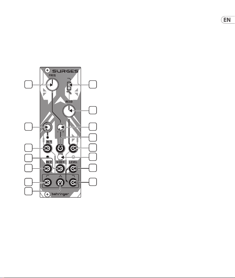
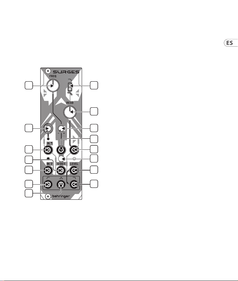
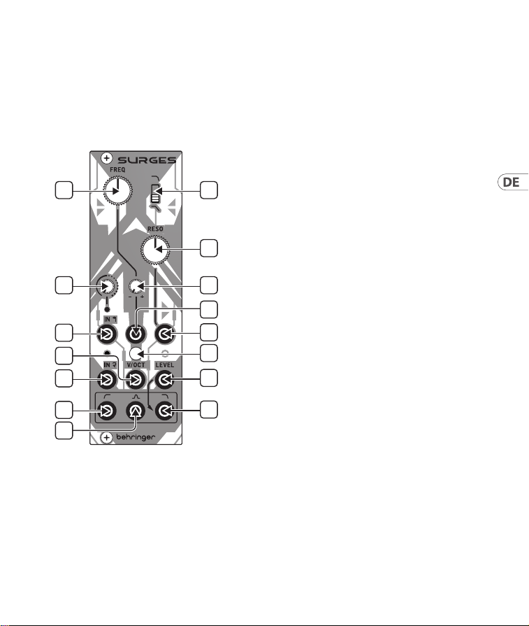
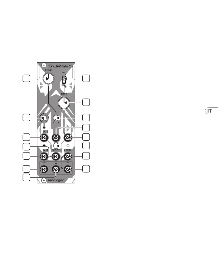
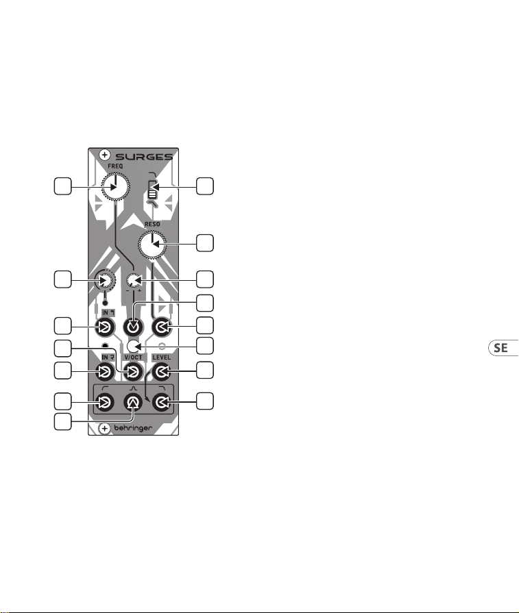
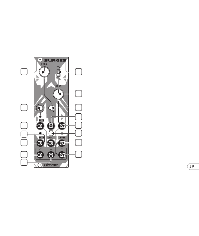
SURGES Controls
1. FREQ – use this control to set the SURGES
cuto frequency.
2. SLOPE – use this switch to set the cuto
slope for the low pass and band pass lters;
up for 24 dB/octave, down for 12 dB/octave.
3. RESO – use this control to set the resonance
level, emphasizing a band of frequencies
around the cuto point. At extreme settings
the SURGES will self-oscillate.
4. INPUT 1 GAIN – use this control to set the
gain for input one. Higher settings will cause
the signal to be over-driven.
5. FREQ CV ATTENUVERTER – use this control
to set the level, and to invert if required, the
frequency control CV.
6. IN 1 – use this 3.5 mm TS jack socket to
input an audio signal with adjustable level/
overdrive from control 4. The LED above
will light when a signal is present and grow
brighter as the gain is increased.
7. FREQ CV IN – use this 3.5 mm TS jack socket
to control the SURGES’ cuto frequency from
an external CV source, via the attenuverter 5.
Range is -8 V to +8 V.
8. RESO CV IN – use this 3.5 mm TS jack socket
to control the SURGES’ resonance level from
an external CV source. Range is -8 V to +8 V.
9. V/OCT CALIBRATION – if the volt/octave
tracking needs to be calibrated remove
this cover and use a suitable screwdriver to
adjust the trimmer below. Please note that
this should only be carried out by competent
personnel. See CALIBRATION below.
(EN) Controls
1
4
6
10
13
14
11
2
3
5
9
7
8
12
15
15Quick Start Guide14 SURGES
10. IN 2 – use this 3.5 mm TS jack socket to input
a second, clean, signal into the SURGES. The
LED above will light if a signal is present.
Both inputs can be used simultaneously.
11. V/OCT – use this 3.5 mm TS jack socket to
track the cuto frequency at 1 volt/octave.
Range is -3 V to +7 V.
12. LOW PASS LEVEL – use this 3.5 mm TS jack
to socket control the level of the low pass
output from an external CV source. Range is
0 V (no output) through +5 V (unity) up to
+7 V (compressed). If no external voltage is
used then +7 V is applied internally.
13. HIGH PASS OUT – use this 3.5 mm TS jack
socket to access the high pass lter output.
14. BAND PASS OUT – use this 3.5 mm TS jack
socket to access the band pass lter output.
15. LOW PASS OUT – use this 3.5 mm TS jack
socket to access the low pass lter output.
All outputs can be used simultaneously.
CALIBRATION
1. Disconnect all external CV controls, except
a suitable calibrated 1 volt/octave keyboard
connected to the v/oct input (11).
2. Set the Freq control (1) to around its midway
point, and the Reso control (3) to maximum.
3. Either by ear, or using a tuner, adjust the
trimmer (9) until playing notes one octave
apart produces a correctly tuned octave output
on the low pass output (15).
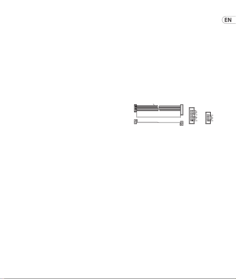
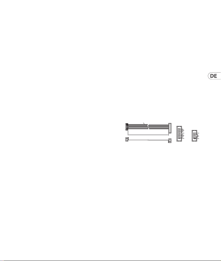
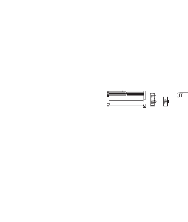
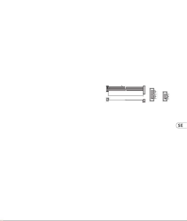
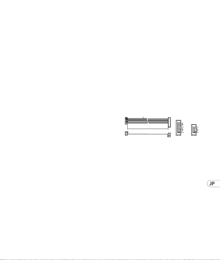
Power Connection
The module comes with the required power cable
for connecting to a standard Eurorack power
supply system. Follow these steps to connect
power to the module. It is easier to make these
connections before the module has been mounted
into a rack case.
1. Turn the power supply or rack case power o
and disconnect the power cable.
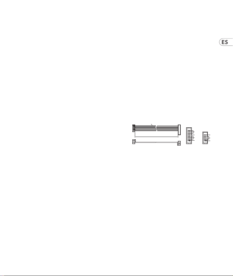
2. Insert the 16-pin connector on the power cable
into the socket on the power supply or rack
case. The connector has a tab that will align
with the gap in the socket, so it cannot be
inserted incorrectly. If the power supply does
not have a keyed socket, be sure to orient pin 1
(-12 V) with the red stripe on the cable.
HOT USED
Red Stripe
200 mm ± 10
15 16
21
P2P1
2
10 9
1
Connect end P1 to the module socket
Connect end P2 to the power supply
+ 12V
- 12V
GROUND
+ 12V
- 12V
GROUND
SURGES Controls
17Quick Start Guide16 SURGES

19Quick Start Guide18 SURGES
3. Insert the 10-pin connector into the socket on
the back of the module. The connector has a
tab that will align with the socket for correct
orientation.
4. After both ends of the power cable have been
securely attached, you may mount the module
in a case and turn on the power supply.
Installation
The necessary screws are included with the
module for mounting in a Eurorack case.
Connect the power cable before mounting.
Depending on the rack case, there may be a series
of xed holes spaced 2 HP apart along the length
of the case, or a track that allows individual
threaded plates to slide along the length of the
case. The free-moving threaded plates allow
precise positioning of the module, but each plate
should be positioned in the approximate relation
to the mounting holes in your module before
attaching the screws.
Hold the module against the Eurorack rails so
that each of the mounting holes are aligned with
a threaded rail or threaded plate. Attach the
screws part way to start, which will allow small
adjustments to the positioning while you get
them all aligned. After the nal position has been
established, tighten the screws down.
21Quick Start Guide20 SURGES
SURGES Controles
1
4
6
10
13
14
11
2
3
5
9
7
8
12
15
(ES) Controles
1. FREQ – usa este control para ajustar la
frecuencia de corte de SURGES.
2. SLOPE – usa este interruptor para congurar
la pendiente de corte para los ltros de
paso bajo y paso de banda; hacia arriba para
24 dB/octava, hacia abajo para 12 dB/octava.
3. RESO – usa este control para ajustar el nivel
de resonancia, enfatizando una banda de
frecuencias alrededor del punto de corte.
En conguraciones extremas, SURGES se
autooscilará.
4. INPUT 1 GAIN – usa este control para
ajustar la ganancia de la entrada uno.
Ajustes más altos harán que la señal sea
sobrealimentada.
5. FREQ CV ATTENUVERTER – usa este control
para ajustar el nivel y, si es necesario, invertir
el CV del control de frecuencia.
6. IN 1 – usa este conector jack TS de 3,5 mm
para introducir una señal de audio con
nivel ajustable/sobrealimentación desde el
control 4. El LED encima se encenderá cuando
haya una señal presente y se iluminará más
al aumentar la ganancia.
7. FREQ CV IN – usa este conector jack TS
de 3,5 mm para controlar la frecuencia
de corte de SURGES desde una fuente CV
externa, a través del atenuador 5. El rango
es de -8 V a +8 V.
8. RESO CV IN – usa este conector jack TS de
3,5 mm para controlar el nivel de resonancia
de SURGES desde una fuente CV externa.
El rango es de -8 V a +8 V.
23Quick Start Guide22 SURGES
9. V/OCT CALIBRATION – si es necesario
calibrar el seguimiento de voltaje/octava,
retire esta cubierta y use un destornillador
adecuado para ajustar el trimmer debajo.
Tenga en cuenta que esto solo debe ser
realizado por personal competente.
Ver CALIBRACIÓN más abajo.
10. IN 2 – usa este conector jack TS de 3,5 mm
para introducir una segunda señal limpia
en SURGES. El LED encima se encenderá si
hay una señal presente. Ambas entradas se
pueden usar simultáneamente.
11. V/OCT – usa este conector jack TS de 3,5 mm
para seguir la frecuencia de corte a 1 voltio/
octava. El rango es de -3 V a +7 V.
12. LOW PASS LEVEL – usa este conector jack
TS de 3,5 mm para controlar el nivel de salida
de paso bajo desde una fuente CV externa.
El rango es de 0 V (sin salida) a +5 V (unidad)
hasta +7 V (comprimido). Si no se usa voltaje
externo, se aplican +7 V internamente.
13. HIGH PASS OUT – usa este conector jack TS
de 3,5 mm para acceder a la salida del ltro
de paso alto.
14. BAND PASS OUT – usa este conector jack TS
de 3,5 mm para acceder a la salida del ltro
de paso de banda.
15. LOW PASS OUT – usa este conector jack TS
de 3,5 mm para acceder a la salida del ltro
de paso bajo.
Todas las salidas se pueden usar simultáneamente.
SURGES Controles
CALIBRACIÓN
1. Desconecte todos los controles externos de
CV, excepto un teclado calibrado adecuado
de 1 voltio/octava conectado a la entrada
V/OCT (11).
2. Ajuste el control de frecuencia (1)
aproximadamente a la mitad y el control de
resonancia (3) al máximo.
3. Ya sea por oído o utilizando un anador, ajuste
el trimmer (9) hasta que tocar notas separadas
por una octava produzca una salida de octava
correctamente anada en la salida de paso
bajo (15).
Conexión Eléctrica
El módulo viene con el cable de alimentación
necesario para conectarse a un sistema de
suministro de energía Eurorack estándar. Siga
estos pasos para conectar la alimentación al
módulo. Es más fácil realizar estas conexiones
antes de que el módulo se haya montado en una
caja de rack.
1. Apague la fuente de alimentación o la caja del
bastidor y desconecte el cable de alimentación.
2. Inserte el conector de 16 clavijas del cable
de alimentación en la toma de la fuente
de alimentación o en la caja del bastidor.
El conector tiene una pestaña que se alineará
con el espacio en el zócalo, por lo que no se
puede insertar incorrectamente. Si la fuente
HOT USED
Red Stripe
200 mm ± 10
15 16
21
P2P1
2
10 9
1
Connect end P1 to the module socket
Connect end P2 to the power supply
+ 12V
- 12V
GROUND
+ 12V
- 12V
GROUND

25Quick Start Guide24 SURGES
de alimentación no tiene un enchufe con llave,
asegúrese de orientar el pin 1 (-12 V) con la
raya roja en el cable.
3. Inserte el conector de 10 pines en el zócalo en
la parte posterior del módulo. El conector tiene
una pestaña que se alineará con el enchufe
para una orientación correcta.
4. Una vez que ambos extremos del cable de
alimentación se hayan conectado de forma
segura, puede montar el módulo en una caja y
encender la fuente de alimentación.
Instalación
Los tornillos necesarios se incluyen con el módulo
para su montaje en una caja Eurorack. Conecte el
cable de alimentación antes del montaje.
Dependiendo de la caja del bastidor, puede haber
una serie de oricios jos separados 2 HP a lo largo
de la caja, o una pista que permita que las placas
roscadas individuales se deslicen a lo largo de
la caja. Las placas roscadas de movimiento libre
permiten un posicionamiento preciso del módulo,
pero cada placa debe colocarse en una relación
aproximada con los oricios de montaje en su
módulo antes de colocar los tornillos.
Sostenga el módulo contra los rieles Eurorack de
modo que cada uno de los oricios de montaje
esté alineado con un riel o placa roscada. Coloque
los tornillos parcialmente para comenzar, lo
que permitirá pequeños ajustes en la posición
mientras los alinea todos. Una vez establecida la
posición nal, apriete los tornillos.
27Quick Start Guide26 SURGES
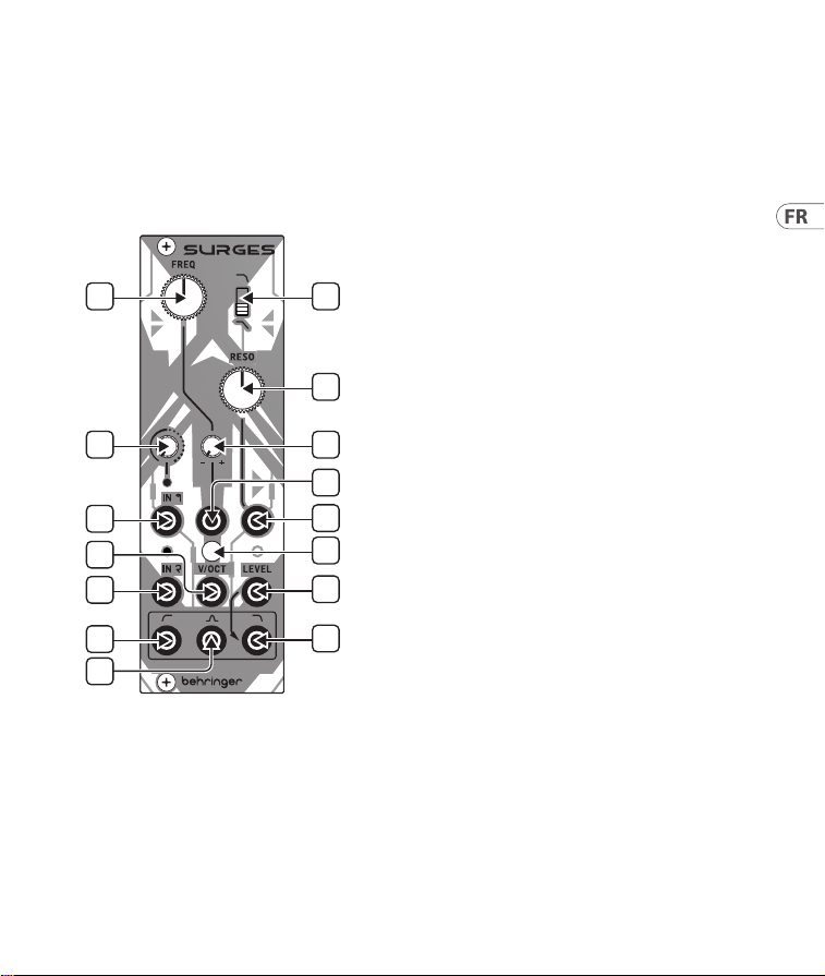
SURGES Réglages
1
4
6
10
13
14
11
2
3
5
9
7
8
12
15
(FR) Réglages
1. FREQ – utilisez ce contrôle pour régler la
fréquence de coupure des SURGES.
2. SLOPE – utilisez cet interrupteur pour régler
la pente de coupure pour les ltres passe-bas
et passe-bande ; vers le haut pour 24 dB/
octave, vers le bas pour 12 dB/octave.
3. RESO – utilisez ce contrôle pour régler le
niveau de résonance, en mettant l’accent sur
une bande de fréquences autour du point de
coupure. Aux réglages extrêmes, les SURGES
s’auto-oscilleront.
4. INPUT 1 GAIN – utilisez ce contrôle
pour régler le gain de l’entrée un.
Des réglages plus élevés provoqueront
une suralimentation du signal.
5. FREQ CV ATTENUVERTER – utilisez ce
contrôle pour régler le niveau, et pour
inverser si nécessaire, le CV de contrôle de
fréquence.
6. IN 1 – utilisez cette prise jack TS de 3,5 mm
pour entrer un signal audio avec un niveau
réglable/suralimentation depuis le contrôle
4. La LED s’allumera lorsque qu’un signal est
présent et deviendra plus brillante à mesure
que le gain augmente.
7. FREQ CV IN – utilisez cette prise jack TS
de 3,5 mm pour contrôler la fréquence de
coupure des SURGES depuis une source CV
externe, via l’atténuateur 5. La plage est de
-8 V à +8 V.
8. RESO CV IN – utilisez cette prise jack TS
de 3,5 mm pour contrôler le niveau de
résonance des SURGES depuis une source CV
externe. La plage est de -8 V à +8 V.
29Quick Start Guide28 SURGES
9. V/OCT CALIBRATION – si le suivi volt/
octave doit être calibré, retirez ce couvercle
et utilisez un tournevis adapté pour ajuster
le trimmer en dessous. Veuillez noter que
cela ne doit être réalisé que par un personnel
compétent. Voir CALIBRATION ci-dessous.
10. IN 2 – utilisez cette prise jack TS de 3,5 mm
pour entrer un deuxième signal propre dans
les SURGES. La LED s’allumera si un signal
est présent. Les deux entrées peuvent être
utilisées simultanément.
11. V/OCT – utilisez cette prise jack TS de
3,5 mm pour suivre la fréquence de coupure
à 1 volt/octave. La plage est de -3 V à +7 V.
12. LOW PASS LEVEL – utilisez cette prise jack
TS de 3,5 mm pour contrôler le niveau de
sortie du passe-bas depuis une source CV
externe. La plage est de 0 V (pas de sortie)
à +5 V (unité) jusqu’à +7 V (compressé).
Si aucune tension externe n’est utilisée,
+7 V est appliqué en interne.
13. HIGH PASS OUT – utilisez cette prise jack TS
de 3,5 mm pour accéder à la sortie du ltre
passe-haut.
14. BAND PASS OUT – utilisez cette prise jack TS
de 3,5 mm pour accéder à la sortie du ltre
passe-bande.
15. LOW PASS OUT – utilisez cette prise jack TS
de 3,5 mm pour accéder à la sortie du ltre
passe-bas.
Toutes les sorties peuvent être utilisées
simultanément.
CALIBRAGE
1. Déconnectez tous les contrôles externes de
CV, sauf un clavier calibré approprié de 1 volt/
octave connecté à l’entrée V/OCT (11).
2. Réglez le contrôle de fréquence (1) environ à
mi-course et le contrôle de résonance (3) au
maximum.
3. Soit à l’oreille, soit à l’aide d’un accordeur,
ajustez le potentiomètre (9) jusqu’à ce que la
reproduction de notes séparées d’une octave
produise une sortie d’octave correctement
accordée sur la sortie passe-bas (15).
Connexion Électrique
Le module est livré avec le câble d’alimentation
requis pour la connexion à un système
d’alimentation standard Eurorack. Suivez ces
étapes pour connecter l’alimentation au module.
Il est plus facile d’eectuer ces connexions avant
que le module n’ait été monté dans un boîtier
de rack.
1. Mettez le bloc d’alimentation ou le boîtier
de rack hors tension et débranchez le câble
d’alimentation.
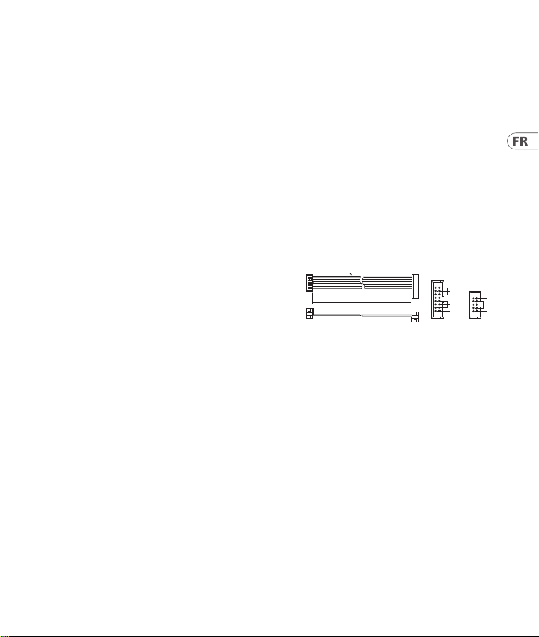
2. Insérez le connecteur à 16 broches du
câble d’alimentation dans la prise du bloc
d’alimentation ou du boîtier du rack.
Le connecteur a une languette qui s’alignera
avec l’espace dans la prise, de sorte qu’il ne
peut pas être inséré de manière incorrecte.
HOT USED
Red Stripe
200 mm ± 10
15 16
21
P2P1
2
10 9
1
Connect end P1 to the module socket
Connect end P2 to the power supply
+ 12V
- 12V
GROUND
+ 12V
- 12V
GROUND
SURGES Réglages

31Quick Start Guide30 SURGES
Si le bloc d’alimentation n’a pas de prise à clé,
veillez à orienter la broche 1 (-12 V) avec la
bande rouge sur le câble.
3. Insérez le connecteur à 10 broches dans la prise
à l’arrière du module. Le connecteur a une
languette qui s’alignera avec la prise pour une
orientation correcte.
4. Une fois que les deux extrémités du câble
d’alimentation ont été solidement xées, vous
pouvez monter le module dans un boîtier et
allumer l’alimentation.
Installation
Les vis nécessaires sont incluses avec le module
pour le montage dans un boîtier Eurorack.
Connectez le câble d’alimentation avant
le montage.
Selon le cas de rack, il peut y avoir une série de
trous xes espacés de 2 HP sur la longueur du
cas, ou une piste qui permet aux plaques letées
individuelles de glisser le long de la longueur
du cas. Les plaques letées à déplacement
libre permettent un positionnement précis du
module, mais chaque plaque doit être positionnée
approximativement par rapport aux trous de
montage de votre module avant de xer les vis.
Maintenez le module contre les rails Eurorack
de sorte que chacun des trous de montage soit
aligné avec un rail leté ou une plaque letée.
Fixez les vis partiellement pour commencer,
ce qui permettra de petits ajustements au
positionnement pendant que vous les alignerez
tous. Une fois la position nale établie, serrez les
vis vers le bas.
33Quick Start Guide32 SURGES
SURGES Bedienelemente
1
4
6
10
13
14
11
2
3
5
9
7
8
12
15
(DE) Bedienelemente
1. FREQ – verwenden Sie diese Steuerung, um
die SURGES-Cuto-Frequenz einzustellen.
2. SLOPE – verwenden Sie diesen Schalter,
um die Cuto-Steilheit für die Tiefpass- und
Bandpasslter einzustellen; hoch für 24 dB/
Oktave, runter für 12 dB/Oktave.
3. RESO – verwenden Sie diese Steuerung,
um den Resonanzpegel einzustellen und
eine Bandbreite von Frequenzen um den
Cuto-Punkt zu betonen. Bei extremen
Einstellungen wird SURGES selbstoszillieren.
4. INPUT 1 GAIN – verwenden Sie diese
Steuerung, um den Eingangspegel
für Eingang eins einzustellen. Höhere
Einstellungen führen zu einer Übersteuerung
des Signals.
5. FREQ CV ATTENUVERTER – verwenden
Sie diese Steuerung, um den Pegel des
Frequenz-CV einzustellen und bei Bedarf
zu invertieren.
6. IN 1 – verwenden Sie diese 3,5-mm-TS-
Klinkenbuchse, um ein Audiosignal mit
einstellbarem Pegel/Übersteuerung von
Steuerung 4 einzugeben. Die LED oben
leuchtet auf, wenn ein Signal vorhanden ist,
und wird heller, wenn der Pegel erhöht wird.
7. FREQ CV IN – verwenden Sie diese
3,5-mm-TS-Klinkenbuchse, um die
SURGES-Cuto-Frequenz von einer externen
CV-Quelle aus über den Attenuverter 5 zu
steuern. Der Bereich beträgt -8 V bis +8 V.
8. RESO CV IN – verwenden Sie diese
3,5-mm-TS-Klinkenbuchse, um den
Resonanzpegel von SURGES von
einer externen CV-Quelle aus zu
steuern. Der Bereich beträgt -8 V bis +8 V.
35Quick Start Guide34 SURGES
9. V/OCT CALIBRATION – Wenn die Volt/
Oktav-Verfolgung kalibriert werden
muss, entfernen Sie diese Abdeckung
und verwenden Sie einen geeigneten
Schraubendreher, um den Trimmer darunter
einzustellen. Beachten Sie, dass dies nur
von kompetentem Personal durchgeführt
werden sollte. Siehe KALIBRIERUNG unten.
10. IN 2 – verwenden Sie diese 3,5-mm-TS-
Klinkenbuchse, um ein zweites, sauberes
Signal in die SURGES einzugeben. Die
LED oben leuchtet auf, wenn ein Signal
vorhanden ist. Beide Eingänge können
gleichzeitig verwendet werden.
11. V/OCT – verwenden Sie diese 3,5-mm-TS-
Klinkenbuchse, um die Cuto-Frequenz mit
1 V/Oktave zu verfolgen. Der Bereich beträgt
-3 V bis +7 V.
12. LOW PASS LEVEL – verwenden Sie diese
3,5-mm-TS-Klinkenbuchse, um den Pegel
des Tiefpassausgangs von einer externen
CV-Quelle zu steuern. Der Bereich geht von
0 V (kein Ausgang) über +5 V (Einheit) bis
+7 V (komprimiert). Wenn keine externe
Spannung verwendet wird, werden intern
+7 V angewendet.
13. HIGH PASS OUT – verwenden Sie diese
3,5-mm-TS-Klinkenbuchse, um auf den
Ausgang des Hochpasslters zuzugreifen.
14. BAND PASS OUT – verwenden Sie diese
3,5-mm-TS-Klinkenbuchse, um auf den
Ausgang des Bandpasslters zuzugreifen.
15. LOW PASS OUT – verwenden Sie diese
3,5-mm-TS-Klinkenbuchse, um auf den
Ausgang des Tiefpasslters zuzugreifen.
Alle Ausgänge können gleichzeitig verwendet
werden.
SURGES Bedienelemente
KALIBRIERUNG
1. Trennen Sie alle externen CV-Steuerungen,
außer einem geeigneten kalibrierten 1 Volt/
Oktave-Keyboard, das mit dem V/OCT-Eingang
(11) verbunden ist.
2. Stellen Sie die Freq-Regelung (1) auf etwa
die Mitte und die Reso-Regelung (3) auf das
Maximum ein.
3. Einstellung entweder nach Gehör oder
mit einem Stimmgerät den Trimmer (9)
so einstellen, dass beim Spielen von Noten,
die eine Oktave voneinander entfernt sind,
eine korrekt gestimmte Oktav-Ausgabe am
Tiefpass-Ausgang (15) erzeugt wird.
Netzanschluss
Das Modul wird mit dem erforderlichen
Stromkabel für den Anschluss an ein Standard-
Eurorack-Stromversorgungssystem geliefert.
Befolgen Sie diese Schritte, um das Modul
mit Strom zu versorgen. Es ist einfacher, diese
Verbindungen herzustellen, bevor das Modul in
ein Rackgehäuse eingebaut wurde.
1. Schalten Sie das Netzteil oder das Rackgehäuse
aus und ziehen Sie das Netzkabel ab.
2. Stecken Sie den 16-poligen Stecker am
Netzkabel in die Buchse am Netzteil oder im
Rack-Gehäuse. Der Anschluss verfügt über
eine Lasche, die an der Lücke in der Buchse
ausgerichtet ist, sodass sie nicht falsch
eingesetzt werden kann. Wenn das Netzteil
HOT USED
Red Stripe
200 mm ± 10
15 16
21
P2P1
2
10 9
1
Connect end P1 to the module socket
Connect end P2 to the power supply
+ 12V
- 12V
GROUND
+ 12V
- 12V
GROUND

37Quick Start Guide36 SURGES
keine Schlüsselbuchse hat, achten Sie darauf,
Pin 1 (-12 V) mit dem roten Streifen am
Kabel auszurichten.
3. Stecken Sie den 10-poligen Stecker in die
Buchse auf der Rückseite des Moduls.
Der Anschluss verfügt über eine Lasche,
die zur korrekten Ausrichtung an der Buchse
ausgerichtet wird.
4. Nachdem beide Enden des Netzkabels fest
angeschlossen wurden, können Sie das
Modul in einem Gehäuse montieren und die
Stromversorgung einschalten.
Installation
Die erforderlichen Schrauben sind im
Lieferumfang des Moduls für die Montage in
einem Eurorack-Gehäuse enthalten. Schließen Sie
das Netzkabel vor der Montage an.
Abhängig vom Rack-Gehäuse kann es eine Reihe
von festen Löchern geben, die entlang der Länge
des Gehäuses 2 PS voneinander entfernt sind, oder
eine Schiene, mit der einzelne Gewindeplatten
entlang der Länge des Gehäuses gleiten können.
Die frei beweglichen Gewindeplatten ermöglichen
eine präzise Positionierung des Moduls.
Jede Platte sollte jedoch in der ungefähren
Beziehung zu den Befestigungslöchern in
Ihrem Modul positioniert werden, bevor Sie die
Schrauben anbringen.
Halten Sie das Modul so gegen die Eurorack-
Schienen, dass jedes der Befestigungslöcher mit
einer Gewindeschiene oder einer Gewindeplatte
ausgerichtet ist. Bringen Sie die Schrauben
teilweise an, um zu beginnen. Dadurch können
Sie die Position geringfügig anpassen, während
Sie alle ausrichten. Ziehen Sie die Schrauben
fest, nachdem die endgültige Position
festgelegt wurde.
39Quick Start Guide38 SURGES
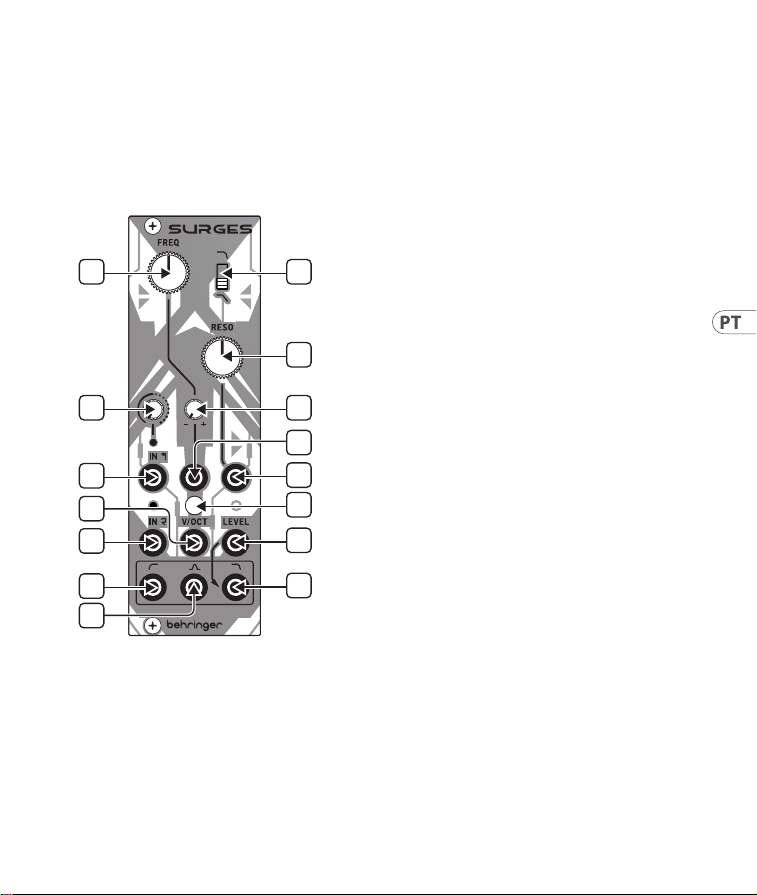
SURGES Controles
1
4
6
10
13
14
11
2
3
5
9
7
8
12
15
(PT) Controles
1. FREQ – use este controle para denir a
frequência de corte dos SURGES.
2. SLOPE – use esta chave para denir a
inclinação de corte dos ltros passa-baixa e
passa-banda; para cima para 24 dB/oitava,
para baixo para 12 dB/oitava.
3. RESO – use este controle para denir o nível
de ressonância, enfatizando uma banda de
frequências em torno do ponto de corte.
Em congurações extremas, os SURGES
autooscilarão.
4. INPUT 1 GAIN – use este controle
para denir o ganho para a entrada
um. Congurações mais altas causarão
sobrealimentação do sinal.
5. FREQ CV ATTENUVERTER – use este
controle para denir o nível e, se necessário,
inverter o CV do controle de frequência.
6. IN 1 – use esta tomada TS de 3,5 mm para
inserir um sinal de áudio com nível ajustável/
sobrealimentação do controle 4. O LED acima
acenderá quando houver um sinal presente
e cará mais brilhante conforme o
ganho aumenta.
7. FREQ CV IN – use esta tomada TS de
3,5 mm para controlar a frequência de
corte dos SURGES a partir de uma fonte
CV externa, via o atenuador 5. A faixa
é de -8 V a +8 V.
8. RESO CV IN – use esta tomada TS de 3,5 mm
para controlar o nível de ressonância dos
SURGES a partir de uma fonte CV externa.
A faixa é de -8 V a +8 V.
41Quick Start Guide40 SURGES
9. V/OCT CALIBRATION – se o rastreamento
volts/oitavas precisar ser calibrado, remova
esta tampa e use uma chave de fenda
adequada para ajustar o trimmer abaixo.
Tenha em mente que isso só deve ser feito
por pessoal competente. Veja a
CALIBRAÇÃO abaixo.
10. IN 2 – use esta tomada TS de 3,5 mm para
inserir um segundo sinal limpo nos SURGES.
O LED acima acenderá se houver um sinal
presente. Ambas as entradas podem ser
usadas simultaneamente.
11. V/OCT – use esta tomada TS de 3,5 mm para
rastrear a frequência de corte a 1 volt/oitava.
A faixa é de -3 V a +7 V.
12. LOW PASS LEVEL – use esta tomada TS
de 3,5 mm para controlar o nível da saída
de passa-baixa a partir de uma fonte CV
externa. A faixa é de 0 V (sem saída)
a +5 V (unidade) até +7 V (comprimida).
Se nenhuma tensão externa for usada,
+7 V será aplicado internamente.
13. HIGH PASS OUT – use esta tomada TS
de 3,5 mm para acessar a saída do ltro
passa-alto.
14. BAND PASS OUT – use esta tomada TS
de 3,5 mm para acessar a saída do ltro
passa-banda.
15. LOW PASS OUT – use esta tomada TS
de 3,5 mm para acessar a saída do ltro
passa-baixa.
Todas as saídas podem ser usadas
simultaneamente.
CALIBRAÇÃO
1. Desconecte todos os controles externos de CV,
exceto um teclado calibrado adequado de 1
volt/oktav conectado à entrada V/OCT (11).
2. Ajuste o controle de frequência (1) para
aproximadamente o meio do caminho, e o
controle de ressonância (3) para o máximo.
3. Ajuste o trimmer (9) até que, ao tocar notas
separadas por uma oitava, produza uma saída
de oitava corretamente anada na saída de
passagem de baixa frequência (15), seja por
ouvido ou usando um anador.
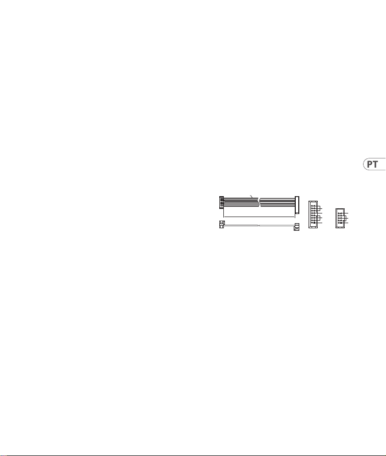
Conexão de Força
O módulo vem com o cabo de alimentação
necessário para conectar a um sistema de fonte de
alimentação Eurorack padrão. Siga estas etapas
para conectar a alimentação ao módulo. É mais
fácil fazer essas conexões antes que o módulo seja
montado em um gabinete de rack.
1. Desligue a fonte de alimentação ou o gabinete
do rack e desconecte o cabo de alimentação.
2. Insira o conector de 16 pinos do cabo
de alimentação no soquete da fonte de
alimentação ou no gabinete do rack. O
conector possui uma aba que se alinhará
com a lacuna no soquete, portanto, não pode
ser inserido incorretamente. Se a fonte de
alimentação não tiver um soquete chaveado,
certique-se de orientar o pino 1 (-12 V) com a
faixa vermelha no cabo.
HOT USED
Red Stripe
200 mm ± 10
15 16
21
P2P1
2
10 9
1
Connect end P1 to the module socket
Connect end P2 to the power supply
+ 12V
- 12V
GROUND
+ 12V
- 12V
GROUND
SURGES Controles

43Quick Start Guide42 SURGES
3. Insira o conector de 10 pinos no soquete na
parte traseira do módulo. O conector possui
uma guia que se alinha ao soquete para
orientação correta.
4. Depois que ambas as extremidades do cabo de
alimentação forem conectadas com segurança,
você pode montar o módulo em uma caixa e
ligar a fonte de alimentação.
Instalação
Os parafusos necessários estão incluídos com
o módulo para montagem em uma caixa
Eurorack. Conecte o cabo de alimentação antes
da montagem.
Dependendo da caixa do rack, pode haver uma
série de orifícios xos espaçados de 2 HP ao
longo do comprimento da caixa, ou um trilho
que permite que placas roscadas individuais
deslizem ao longo do comprimento da caixa.
As placas roscadas de movimento livre permitem
o posicionamento preciso do módulo, mas cada
placa deve ser posicionada em relação aproximada
aos orifícios de montagem em seu módulo antes
de prender os parafusos.
Segure o módulo contra os trilhos Eurorack de
forma que cada um dos orifícios de montagem
quem alinhados com um trilho ou placa
rosqueada. Prenda os parafusos parcialmente
para começar, o que permitirá pequenos ajustes
no posicionamento enquanto você os alinha.
Depois de estabelecida a posição nal, aperte
os parafusos.
45Quick Start Guide44 SURGES
SURGES Controlli
1
4
6
10
13
14
11
2
3
5
9
7
8
12
15
(IT) Controlli
1. FREQ – utilizza questo controllo per
impostare la frequenza di taglio di SURGES.
2. SLOPE – utilizza questo interruttore per
impostare la pendenza di taglio per i ltri
passa basso e passa banda; su per 24 dB/
octave, giù per 12 dB/octave.
3. RESO – utilizza questo controllo
per impostare il livello di risonanza,
enfatizzando una banda di frequenze intorno
al punto di taglio. Con impostazioni estreme,
SURGES si autoterminerà.
4. INPUT 1 GAIN – utilizza questo controllo
per impostare il guadagno per l’ingresso
uno. Impostazioni più alte causeranno il
sovraccarico del segnale.
5. FREQ CV ATTENUVERTER – utilizza questo
controllo per impostare il livello e, se
necessario, invertire il CV di controllo della
frequenza.
6. IN 1 – utilizza questo connettore jack TS da
3,5 mm per inserire un segnale audio con
livello regolabile/sovralimentazione dal
controllo 4. L’LED sopra si illuminerà quando
è presente un segnale e diventerà più
luminoso all’aumentare del guadagno.
7. FREQ CV IN – utilizza questo connettore
jack TS da 3,5 mm per controllare la
frequenza di taglio di SURGES da una fonte
CV esterna, tramite l’attenuatore 5. Il range
è -8 V a +8 V.
8. RESO CV IN – utilizza questo connettore
jack TS da 3,5 mm per controllare il livello
di risonanza di SURGES da una fonte CV
esterna. Il range è -8 V a +8 V.
47Quick Start Guide46 SURGES
9. V/OCT CALIBRATION – se è necessaria la
calibrazione del tracciamento volt/octave,
rimuovi questa copertura e utilizza un
cacciavite adatto per regolare il trimmer
sottostante. Si prega di notare che ciò
dovrebbe essere eseguito solo da personale
competente. Vedi CALIBRAZIONE sotto.
10. IN 2 – utilizza questo connettore jack TS
da 3,5 mm per inserire un secondo segnale
pulito in SURGES. L’LED sopra si illuminerà
se è presente un segnale. Entrambi
gli ingressi possono essere utilizzati
contemporaneamente.
11. V/OCT – utilizza questo connettore jack TS
da 3,5 mm per seguire la frequenza di taglio
a 1 volt/octave. Il range è -3 V a +7 V.
12. LOW PASS LEVEL – utilizza questo
connettore jack TS per controllare il livello
dell’uscita passa basso da una fonte CV
esterna. Il range è da 0 V (nessuna uscita) a
+5 V (unità) no a +7 V (compresso). Se non
viene utilizzata tensione esterna, +7 V viene
applicato internamente.
13. HIGH PASS OUT – utilizza questo
connettore jack TS per accedere all’uscita del
ltro passa alto.
14. BAND PASS OUT – utilizza questo
connettore jack TS per accedere all’uscita del
ltro passa banda.
15. LOW PASS OUT – utilizza questo connettore
jack TS per accedere all’uscita del ltro
passa basso.
Tutte le uscite possono essere utilizzate
contemporaneamente.
SURGES Controlli
CALIBRAZIONE
1. Scollegare tutti i controlli esterni CV, ad
eccezione di una tastiera calibrata adeguata da
1 volt/ottava collegata all’ingresso V/OCT (11).
2. Impostare il controllo Freq (1) circa a metà e il
controllo Reso (3) al massimo.
3. O a orecchio, o utilizzando un accordatore,
regolare il trimmer (9) no a quando la
riproduzione di note distanti un’ottava produce
un’uscita di ottava correttamente intonata
sull’uscita passa basso (15).
Connessione di Alimentazione
Il modulo viene fornito con il cavo di
alimentazione necessario per il collegamento
a un sistema di alimentazione Eurorack
standard. Seguire questi passaggi per collegare
l’alimentazione al modulo. È più facile eettuare
questi collegamenti prima che il modulo sia stato
montato in un case rack.
1. Spegnere l’alimentatore o il case del rack e
scollegare il cavo di alimentazione.
2. Inserire il connettore a 16 pin del cavo di
alimentazione nella presa sull’alimentatore
o sulla custodia del rack. Il connettore ha una
linguetta che si allineerà con lo spazio nella
presa, quindi non può essere inserito in modo
errato. Se l’alimentatore non dispone di una
presa con chiave, assicurarsi di orientare il pin 1
(-12 V) con la striscia rossa sul cavo.
HOT USED
Red Stripe
200 mm ± 10
15 16
21
P2P1
2
10 9
1
Connect end P1 to the module socket
Connect end P2 to the power supply
+ 12V
- 12V
GROUND
+ 12V
- 12V
GROUND

49Quick Start Guide48 SURGES
3. Inserire il connettore a 10 pin nella presa
sul retro del modulo. Il connettore ha una
linguetta che si allineerà con la presa per un
corretto orientamento.
4. Dopo che entrambe le estremità del cavo di
alimentazione sono state ssate saldamente, è
possibile montare il modulo in una custodia e
accendere l’alimentatore.
Installazione
Le viti necessarie sono incluse con il modulo per il
montaggio in una custodia Eurorack. Collegare il
cavo di alimentazione prima del montaggio.
A seconda del case del rack, potrebbero esserci una
serie di fori ssi distanziati di 2 HP l’uno dall’altro
lungo la lunghezza del case, o un binario che
consente alle singole piastre lettate di scorrere
lungo la lunghezza del case. Le piastre lettate a
movimento libero consentono un posizionamento
preciso del modulo, ma ciascuna piastra deve
essere posizionata in relazione approssimativa
con i fori di montaggio nel modulo prima di ssare
le viti.
Tenere il modulo contro le guide Eurorack in modo
che ciascuno dei fori di montaggio sia allineato con
una guida lettata o una piastra lettata. Attacca
le viti in parte per iniziare, il che consentirà piccoli
aggiustamenti al posizionamento mentre le fai
allineare tutte. Dopo aver stabilito la posizione
nale, serrare le viti.
51Quick Start Guide50 SURGES
SURGES Bediening
1
4
6
10
13
14
11
2
3
5
9
7
8
12
15
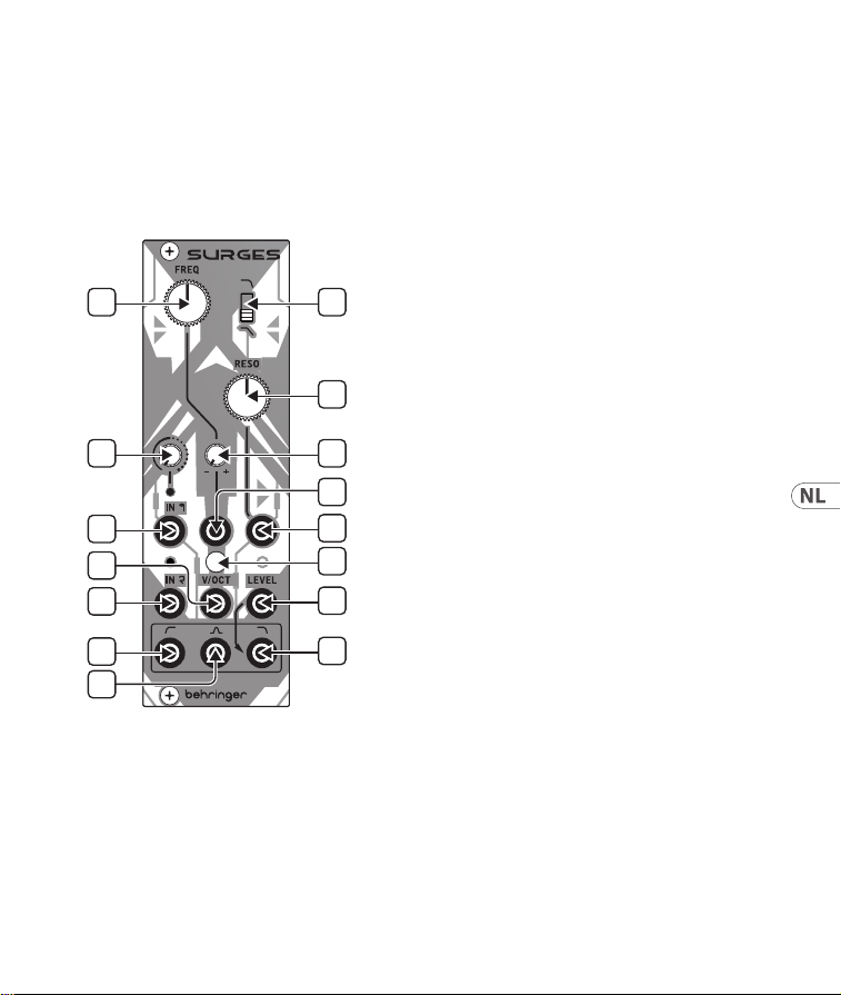
(NL) Bediening
1. FREQ – gebruik deze regeling om de SURGES
afsnijdingsfrequentie in te stellen.
2. SLOPE – gebruik deze schakelaar om de
afsnijdingshelling voor de laagdoorlaat- en
banddoorlaatlters in te stellen; omhoog
voor 24 dB/octaaf, omlaag voor 12 dB/octaaf.
3. RESO – gebruik deze regeling om het
resonantieniveau in te stellen, waarbij
een band van frequenties rond het
afsnijdingspunt wordt benadrukt.
Bij extreme instellingen zal SURGES
zichzelf oscilleren.
4. INPUT 1 GAIN – gebruik deze regeling om
het niveau voor invoer één in te stellen.
Hogere instellingen zullen het signaal
overstuurd maken.
5. FREQ CV ATTENUVERTER – gebruik
deze regeling om het niveau van de
frequentieregeling CV in te stellen en indien
nodig om te keren.
6. IN 1 – gebruik deze 3,5 mm TS-jack-
aansluiting om een audiosignaal in te voeren
met instelbaar niveau/overdrive vanuit
regeling 4. De LED erboven zal oplichten
wanneer er een signaal aanwezig is en
helderder worden naarmate de versterking
wordt verhoogd.
7. FREQ CV IN – gebruik deze 3,5 mm
TS-jack-aansluiting om de SURGES-
afsnijdingsfrequentie te regelen vanuit
een externe CV-bron, via de attenuverter 5.
Het bereik is -8 V tot +8 V.
8. RESO CV IN – gebruik deze 3,5 mm TS-jack-
aansluiting om het resonantieniveau van
de SURGES te regelen vanuit een externe
CV-bron. Het bereik is -8 V tot +8 V.
53Quick Start Guide52 SURGES
9. V/OCT CALIBRATION – Als de volt/
octaaf-tracking moet worden gekalibreerd,
verwijder dan deze afdekking en gebruik een
geschikte schroevendraaier om de trimmer
hieronder aan te passen. Houd er rekening
mee dat dit alleen door bekwaam personeel
moet worden uitgevoerd. Zie KALIBRATIE
hieronder.
10. IN 2 – gebruik deze 3,5 mm TS-jack-
aansluiting om een tweede, schoon signaal
in de SURGES in te voeren. De LED erboven
zal oplichten als er een signaal aanwezig
is. Beide ingangen kunnen tegelijkertijd
worden gebruikt.
11. V/OCT – gebruik deze 3,5 mm TS-jack-
aansluiting om de afsnijdingsfrequentie
bij te houden op 1 volt/octaaf. Het bereik is
-3 V tot +7 V.
12. LOW PASS LEVEL – gebruik deze 3,5 mm
TS-jack-aansluiting om het niveau van de
laagdoorlaatuitgang vanuit een externe
CV-bron te regelen. Het bereik is van 0
V (geen uitgang) tot +5 V (eenheid) tot
+7 V (gecomprimeerd). Als er geen externe
spanning wordt gebruikt, wordt intern
+7 V toegepast.
13. HIGH PASS OUT – gebruik deze 3,5 mm
TS-jack-aansluiting om toegang te krijgen
tot de uitgang van het hoogdoorlaatlter.
14. BAND PASS OUT – gebruik deze 3,5 mm
TS-jack-aansluiting om toegang te krijgen
tot de uitgang van het banddoorlaatlter.
15. LOW PASS OUT – gebruik deze 3,5 mm
TS-jack-aansluiting om toegang te krijgen
tot de uitgang van het laagdoorlaatlter.
Alle uitgangen kunnen tegelijkertijd worden
gebruikt.
KALIBRATIE
1. Koppel alle externe CV-regelingen los, behalve
een geschikt gekalibreerd 1 volt/octaaf
toetsenbord dat is aangesloten op de v/oct-
ingang (11).
2. Stel de Freq-regeling (1) in op ongeveer het
midden en de Reso-regeling (3) op maximaal.
3. Stel de trimmer (9) af door ofwel op het gehoor
of met behulp van een tuner aanpassingen te
maken, totdat het spelen van noten die één
octaaf van elkaar verwijderd zijn een correct
gestemd octaaf-uitgangssignaal produceert op
de lage doorlaatuitgang (15).
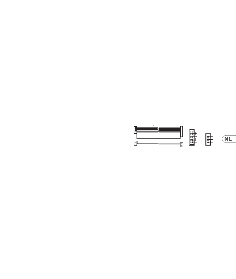
Stroomaansluiting
De module wordt geleverd met de benodigde
voedingskabel voor aansluiting op een standaard
Eurorack-voedingssysteem. Volg deze stappen
om de module van stroom te voorzien. Het is
gemakkelijker om deze aansluitingen te maken
voordat de module in een rekbehuizing
is gemonteerd.
1. Schakel de voeding of de rekbehuizing uit en
koppel de voedingskabel los.
2. Steek de 16-pins connector van de
voedingskabel in de aansluiting op de
voedingseenheid of rekbehuizing.
De connector heeft een lipje dat wordt
uitgelijnd met de opening in de socket,
zodat deze niet verkeerd kan worden
geplaatst. Als de voeding geen contactdoos
HOT USED
Red Stripe
200 mm ± 10
15 16
21
P2P1
2
10 9
1
Connect end P1 to the module socket
Connect end P2 to the power supply
+ 12V
- 12V
GROUND
+ 12V
- 12V
GROUND
SURGES Bediening

55Quick Start Guide54 SURGES
met sleutel heeft, zorg er dan voor dat pen 1
(-12 V) met de rode streep op de kabel
wordt georiënteerd.
3. Steek de 10-pins connector in de aansluiting
aan de achterkant van de module.
De connector heeft een lipje dat uitgelijnd is
met de aansluiting voor de juiste oriëntatie.
4. Nadat beide uiteinden van de voedingskabel
stevig zijn bevestigd, kunt u de module in een
hoesje monteren en de voeding inschakelen.
Installatie
De benodigde schroeven worden bij de module
geleverd voor montage in een Eurorack-koer.
Sluit de voedingskabel aan voor montage.
Afhankelijk van de rackbehuizing kan er een
reeks vaste gaten zijn die 2 HP uit elkaar
liggen over de lengte van de behuizing, of
een rail waarmee afzonderlijke platen met
schroefdraad langs de lengte van de behuizing
kunnen schuiven. De vrij bewegende plaatjes
met schroefdraad maken een nauwkeurige
positionering van de module mogelijk, maar
elke plaat moet ongeveer in verhouding tot de
montagegaten in uw module worden geplaatst
voordat u de schroeven bevestigt.
Houd de module tegen de Eurorack-rails zodat elk
van de montagegaten is uitgelijnd met een rail
met schroefdraad of een plaat met schroefdraad.
Bevestig de schroeven halverwege om te
beginnen, waardoor kleine aanpassingen aan de
positionering mogelijk zijn terwijl u ze allemaal
op één lijn krijgt. Nadat de denitieve positie is
bepaald, draait u de schroeven vast.
57Quick Start Guide56 SURGES
SURGES Kontroller
1
4
6
10
13
14
11
2
3
5
9
7
8
12
15
(SE) Kontroller
1. FREQ – använd denna kontroll för att ställa
in SURGES cuto-frekvens.
2. SLOPE – använd denna brytare för att
ställa in cuto-sluttningen för lågpass- och
bandpasslter; upp för 24 dB/oktav, ner för
12 dB/oktav.
3. RESO – använd denna kontroll för att ställa
in resonansnivån och betona ett band av
frekvenser runt cuto-punkten. Vid extrema
inställningar kommer SURGES självsvänga.
4. INPUT 1 GAIN – använd denna kontroll för
att ställa in förstärkningen för ingång ett.
Högare inställningar kommer att orsaka att
signalen överstyrs.
5. FREQ CV ATTENUVERTER – använd denna
kontroll för att ställa in nivån och invertera
om det behövs, CV för frekvenskontrollen.
6. IN 1 – använd denna 3,5 mm TS-jackkontakt
för att mata in en ljudsignal med
justerbar nivå/överstyrsning från kontroll
4. LED-lampan ovanför lyser när en
signal är närvarande och blir ljusare när
förstärkningen ökas.
7. FREQ CV IN – använd denna 3,5 mm
TS-jackkontakt för att styra SURGES
cuto-frekvens från en extern CV-källa, via
attenuverter 5. Omfånget är -8 V till +8 V.
8. RESO CV IN – använd denna 3,5 mm
TS-jackkontakt för att styra SURGES
resonansnivå från en extern CV-källa.
Omfånget är -8 V till +8 V.
KALIBRERING
1. Koppla loss alla externa CV-kontroller, förutom
ett lämpligt kalibrerat 1 volt/oktav-klaviatur
som är ansluten till v/oct-ingången (11).
2. Ställ in Freq-reglaget (1) till ungefär mitten
och Reso-reglaget (3) till max.
3. Justera trimmern (9) antingen genom örat eller
med hjälp av en stämapparat tills att det spelas
noter som är en oktav isär som ger en korrekt
stämd oktav-utgång på lågpass-utgången (15).
Strömanslutning
Modulen levereras med den strömkabel som
krävs för att ansluta till ett vanligt Eurorack-
nätaggregat. Följ dessa steg för att ansluta
ström till modulen. Det är lättare att göra dessa
anslutningar innan modulen har monterats
i ett rackfodral.
1. Stäng av strömmen eller rackhöljet och koppla
bort strömkabeln.
2. Sätt i den 16-poliga kontakten på strömkabeln
i uttaget på nätaggregatet eller rackfodralet.
Kontaktdonet har en ik som kommer i linje
med springan i uttaget så att den inte kan
sättas in felaktigt. Om strömförsörjningen inte
har ett nyckeluttag, se till att orientera stift 1
(-12 V) med den röda remsan på kabeln.
HOT USED
Red Stripe
200 mm ± 10
15 16
21
P2P1
2
10 9
1
Connect end P1 to the module socket
Connect end P2 to the power supply
+ 12V
- 12V
GROUND
+ 12V
- 12V
GROUND
59Quick Start Guide58 SURGES
9. V/OCT CALIBRATION – Om volt/oktav-
spårning behöver kalibreras, ta bort detta
lock och använd en lämplig skruvmejsel för
att justera trimmern nedanför. Observera
att detta endast bör utföras av kompetent
personal. Se KALIBRERING nedan.
10. IN 2 – använd denna 3,5 mm TS-jackkontakt
för att mata in en andra ren signal i SURGES.
LED-lampan ovanför lyser om en signal
är närvarande. Båda ingångarna kan
användas samtidigt.
11. V/OCT – använd denna 3,5 mm
TS-jackkontakt för att spåra cuto-
frekvensen vid 1 volt/oktav. Omfånget är
-3 V till +7 V.
12. LOW PASS LEVEL – använd denna 3,5 mm
TS-jackkontakt för att kontrollera nivån på
lågpassutgången från en extern CV-källa.
Omfånget är 0 V (ingen utgång) till +5 V
(enhet) upp till +7 V (komprimerad). Om
ingen extern spänning används, tillämpas
+7 V internt.
13. HIGH PASS OUT – använd denna
3,5 mm TS-jackkontakt för att komma åt
högpassltrets utgång.
14. BAND PASS OUT – använd denna
3,5 mm TS-jackkontakt för att komma åt
bandpassltrets utgång.
15. LOW PASS OUT – använd denna
3,5 mm TS-jackkontakt för att komma åt
lågpassltrets utgång.
Alla utgångar kan användas samtidigt.
SURGES Kontroller

3. Sätt i 10-polig kontakt i uttaget på
baksidan av modulen. Kontaktdonet har
en ik som kommer i linje med uttaget för
korrekt orientering.
4. När båda ändarna av strömkabeln har anslutits
ordentligt kan du montera modulen i ett fodral
och slå på strömförsörjningen.
Installation
De nödvändiga skruvarna ingår i modulen
för montering i ett Eurorack-fodral. Anslut
strömkabeln före montering.
Beroende på stativhöljet kan det nnas en serie
fasta hål som är åtskilda 2 hk längs höljets längd
eller ett spår som gör att enskilda gängade plattor
kan glida längs höljets längd. De fritt rörliga
gängade plattorna möjliggör exakt positionering
av modulen, men varje platta bör placeras i
ungefärlig relation till monteringshålen i din
modul innan skruvarna fästs.
Håll modulen mot Eurorack-skenorna så att var
och en av monteringshålen ligger i linje med en
gängad skena eller gängad platta. Fäst skruvarna
delvis för att börja, vilket gör det möjligt att
justera små positioner medan du justerar dem alla.
När den slutliga positionen har fastställts drar du
åt skruvarna.
61Quick Start Guide60 SURGES
63Quick Start Guide62 SURGES
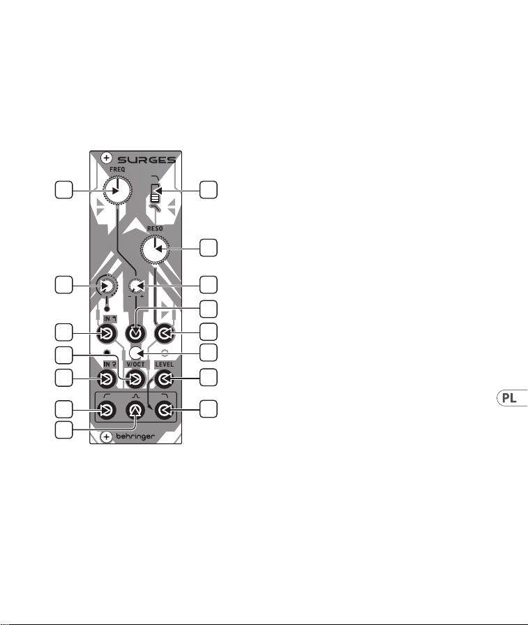
SURGES Sterowanica
1
4
6
10
13
14
11
2
3
5
9
7
8
12
15
(PL) Sterowanica
1. FREQ – użyj tego sterowania, aby ustawić
częstotliwość odcinania SURGES.
2. SLOPE – użyj tego przełącznika, aby
ustawić nachylenie odcinania dla ltrów
dolnoprzepustowych i pasmowych; do góry
na 24 dB/oktawę, do dołu na 12 dB/oktawę.
3. RESO – użyj tego sterowania, aby ustawić
poziom rezonansu, podkreślając pasmo
częstotliwości wokół punktu odcinania.
Przy skrajnych ustawieniach SURGES będą
samowzbudzać się.
4. INPUT 1 GAIN – użyj tego sterowania,
aby ustawić wzmacnianie dla wejścia
jeden. Wyższe ustawienia spowodują
przesterowanie sygnału.
5. FREQ CV ATTENUVERTER – użyj tego
sterowania, aby ustawić poziom i, jeśli
to konieczne, odwrócić CV kontroli
częstotliwości.
6. IN 1 – użyj tego gniazda 3,5 mm TS, aby
wprowadzić sygnał audio o regulowanym
poziomie/przesterowaniu z kontrolki 4.
Dioda LED powyżej zaświeci się, gdy sygnał
jest obecny i będzie jaśniejsza w miarę
zwiększania wzmacniania.
7. FREQ CV IN – użyj tego gniazda 3,5 mm TS,
aby kontrolować częstotliwość odcinania
SURGES z zewnętrznego źródła CV, za
pośrednictwem attenuvertera 5. Zakres to
-8 V do +8 V.
8. RESO CV IN – użyj tego gniazda 3,5 mm
TS, aby kontrolować poziom rezonansu
SURGES z zewnętrznego źródła CV. Zakres to
-8 V do +8 V.
65Quick Start Guide64 SURGES
9. V/OCT CALIBRATION – Jeśli konieczna
jest kalibracja śledzenia wolt/oct, usuń tę
pokrywę i użyj odpowiedniego śrubokrętu
do regulacji trimmera poniżej. Należy
pamiętać, że powinno to być wykonywane
tylko przez kompetentny personel.
Patrz KALIBRACJA poniżej.
10. IN 2 – użyj tego gniazda 3,5 mm TS,
aby wprowadzić drugi, czysty sygnał do
SURGES. Dioda LED powyżej zapali się,
jeśli sygnał jest obecny. Oba wejścia
można używać jednocześnie.
11. V/OCT – użyj tego gniazda 3,5 mm TS,
aby śledzić częstotliwość odcinania na
1 wolt/oktawę. Zakres to -3 V do +7 V.
12. LOW PASS LEVEL – użyj tego gniazda
3,5 mm TS, aby kontrolować poziom wyjścia
dolnoprzepustowego z zewnętrznego źródła
CV. Zakres to od 0 V (brak wyjścia), przez
+5 V (jednostka), do +7 V (skompresowane).
Jeśli nie używa się napięcia zewnętrznego,
wewnętrznie przyjmuje się +7 V.
13. HIGH PASS OUT – użyj tego gniazda
3,5 mm TS, aby uzyskać dostęp do wyjścia
ltra górnoprzepustowego.
14. BAND PASS OUT – użyj tego gniazda
3,5 mm TS, aby uzyskać dostęp do wyjścia
ltra pasmowego.
15. LOW PASS OUT – użyj tego gniazda
3,5 mm TS, aby uzyskać dostęp do wyjścia
ltra dolnoprzepustowego.
Wszystkie wyjścia można używać jednocześnie.
KALIBRACJA
1. Odłącz wszystkie zewnętrzne regulacje CV,
z wyjątkiem odpowiedniego, skalibrowanego
klawiatury o zakresie 1 wolt/oktawa,
podłączonej do wejścia V/OCT (11).
2. Ustaw regulację Freq (1) na około połowie
zakresu, a regulację Reso (3) na maksymalny.
3. Nastaw potencjometr (9) albo słuchowo, albo
za pomocą stroik, dopóki granie dźwięków
oddzielonych o oktawę nie wyda poprawnie
ustawionego dźwięku w oktawie na wyjściu
dolnoprzepustowym (15).
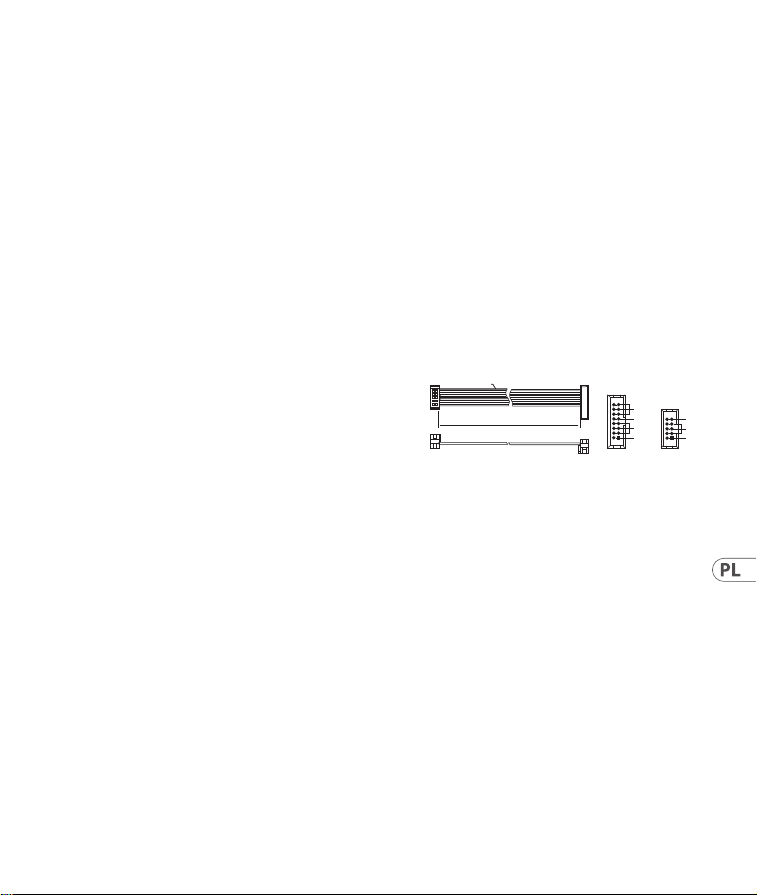
Podłączenie Zasilania
Do modułu dołączony jest wymagany kabel
zasilający do podłączenia do standardowego
systemu zasilania Eurorack. Wykonaj poniższe
czynności, aby podłączyć zasilanie do modułu.
Łatwiej jest wykonać te połączenia przed
zamontowaniem modułu w obudowie rack.
1. Wyłącz zasilacz lub obudowę szafy i odłącz
kabel zasilający.
2. Włóż 16-stykowe złącze przewodu zasilającego
do gniazda w zasilaczu lub w szae typu rack.
Złącze ma wypustkę, która będzie wyrównana
ze szczeliną w gnieździe, więc nie można jej
nieprawidłowo włożyć. Jeśli zasilacz nie ma
gniazda z kluczem, należy zorientować styk 1
(-12 V) z czerwonym paskiem na kablu.
HOT USED
Red Stripe
200 mm ± 10
15 16
21
P2P1
2
10 9
1
Connect end P1 to the module socket
Connect end P2 to the power supply
+ 12V
- 12V
GROUND
+ 12V
- 12V
GROUND
SURGES Sterowanica

67Quick Start Guide66 SURGES
3. Włóż 10-pinowe złącze do gniazda z tyłu
modułu. Złącze ma wypustkę, która będzie
wyrównana z gniazdem, aby zapewnić
prawidłową orientację.
4. Po solidnym zamocowaniu obu końców kabla
zasilającego można zamontować moduł w
obudowie i włączyć zasilacz.
Instalacja
Do modułu dołączone są niezbędne śruby do
montażu w skrzynce Eurorack. Podłącz kabel
zasilający przed montażem.
W zależności od obudowy szafy może występować
szereg stałych otworów rozmieszczonych w
odstępach 2 HP na całej długości obudowy lub
prowadnica, która umożliwia przesuwanie
pojedynczych gwintowanych płyt wzdłuż całej
obudowy. Swobodnie poruszające się gwintowane
płytki umożliwiają precyzyjne ustawienie
modułu, ale każda płyta powinna być ustawiona w
przybliżeniu w stosunku do otworów montażowych
w module przed przykręceniem śrub.
Przytrzymaj moduł na szynach Eurorack, tak aby
każdy z otworów montażowych był wyrównany z
szyną gwintowaną lub płytą gwintowaną. Wkręć
śruby częściowo, aby rozpocząć, co pozwoli na
drobne korekty położenia, gdy wszystkie zostaną
wyrównane. Po ustaleniu ostatecznego położenia
dokręcić śruby.
69Quick Start Guide68 SURGES
SURGES コントロール
1
4
6
10
13
14
11
2
3
5
9
7
8
12
15
(JP) コントロール
1. FREQ – このコントロ ール を 使 用して
SURGES のカットオフ周 波 数 を 設 定し
ます。
2. SLOPE – この スイッチを 使 用 して、
ローパスとバンドパスフィルタのカ
ット オ フ ス ロ ープ を 設 定 し ま す。上 げ
ると 24 dB/オ ク タ ー ブ 、下 げ る と 12 dB/
オクターブ です。
3. RESO – このコントロール を 使 用して、
カットオフポイント周辺の周 波 数 バ
ンドを強 調する共 鳴レベルを設 定し
ます。極端な設定では SURGES は自己
振 動します。
4. INPUT 1 GAIN – このコントロール を
使 用 し て 、入 力 1 のゲインを設 定し
ま す 。高 い 設 定 で は 信 号 が オ ー バ ー ド
ライブされます。
5. FREQ CV ATTENUVERTER – このコント
ロ ー ル を 使 用 して 、周 波 数 制 御 CV
の レ ベ ル を 設 定 し 、必 要 に 応 じ て 反
転します。
6. IN 1 – この 3.5 mm TS ジャックソケッ
トを使用して、コントロール 4 からレ
ベル/オーバードライブ 調整可能なオ
ーディオ信号を入力します。上にあ
る LED は信号が 存在すると点灯し、
ゲインが増加するにつれて明るくな
りま す。
7. FREQ CV IN – この 3.5 mm TS ジャックソ
ケットを使用して、衰退器 5 を介して
外部 CV ソースから SURGES の カットオ
フ周波数を制御します。範囲は -8 V
から +8 V です。
8. RESO CV IN – この 3.5 mm TS ジャック
ソケットを使用して、外部 CV ソース
から SURGES の共 鳴レベルを制 御しま
す。範 囲 は -8 V から +8 V です。
71Quick Start Guide70 SURGES
9. V/OCT CALIBRATION – もし電圧/オクタ
ーブトラッキングのキャリブレーショ
ンが必要なら、このカバーを取り外
して、下のトリマを調整するために適
切なドライバ を 使 用しま す。これ は有
能な人員によってのみ行われるべき
です。以下のキャリブレーションを参
照してください 。
10. IN 2 – この 3.5 mm TS ジャックソケ ット
を 使 用 し て 、第 2 のクリーン な 信 号を
SURGES に 入 力 し ま す。上 に あ る LED は
信 号 が 存 在 す る と 点 灯 し ま す 。両 方 の
入 力を同 時 に使 用で きま す。
11. V/OCT – この 3.5 mm TS ジャックソケッ
トを使用して、 1 V/オクターブ で のカッ
トオフ周 波 数をトラッキングしま す。
範囲は -3 V から +7 V です。
12. LOW PASS LEVEL – この 3.5 mm TS ジャッ
ク を 使 用 し て 、外 部 CV ソースからの
ローパ ス 出力のレ ベルを制 御します。
範囲は 0 V ( 出 力 な し )か ら +5 V (ユニ
テ ィ )か ら +7 V ( 圧 縮 )で す 。外 部 電
圧が使用されていない場 合は内部
的に +7 V が 適 用されます。
13. HIGH PASS OUT – この 3.5 mm TS ジャッ
クソケットを 使 用して、ハイパ スフィ
ルタの 出力にアクセスします。
14. BAND PASS OUT – この 3.5 mm TS ジャッ
クソケットを使用して、バンドパスフ
ィルタの 出 力にアクセ スします。
15. LOW PASS OUT – この 3.5 mm TS ジャッ
クソケットを使用して、ローパスフィ
ルタの 出力にアクセスします。
すべての出力は同時に使用できます。
SURGES コントロール
キャリブレーション
1. V/OCT 入 力( 11)に接続された適切に校
正された 1 ボルト/オクターブキーボー
ド を 除 い て 、す べ て の 外 部 CV コントロ
ール を 切 断します。
2. Freq コ ン ト ロ ー ル( 1)を中間点に設
定し、 Reso コ ン ト ロ ー ル( 3)を 最 大 に
します。
3. 耳 で 調 整 す る か 、チ ュ ー ナ ー を 使 用
し て 、ト リ マ( 9)を 調 整 し 、 1 オクターブ
離れた音を演奏しても、ローパス出力
(15)上 で 正 確 に 調 整 さ れ た オ ク タ ー ブ
出力を出力するようにします。
電源接続
モ ジ ュ ー ル に は 、標 準 の Eurorack 電源シ
ステムに接続するために必要な電源ケー
ブルが付属しています。以下の手順に従
っ て 、モ ジ ュ ー ル を Eurorack ケースに接 続
します。
1. 電源またはラックケースの電源を切り、
電 源 ケーブル を 外します。
2. 電 源 ケーブル の 16 ピンコネクタを電 源
装 置 また はラックケースのソケットに
差し込みます。コネクタには、ソケット
のギャップに合わせて配置されるタブ
があるため、正しく挿入することはで
き ま せ ん 。電 源 装 置 に キ ー 付 き ソ ケ ッ
ト が な い 場 合 は 、ケ ー ブ ル の 赤 い ス ト
ライプをピン 1 (-12 V) に 向けて 指 定して
ください。
HOT USED
Red Stripe
200 mm ± 10
15 16
21
P2P1
2
10 9
1
Connect end P1 to the module socket
Connect end P2 to the power supply
+ 12V
- 12V
GROUND
+ 12V
- 12V
GROUND

73Quick Start Guide72 SURGES
3. モジュール背面のソケットに 10 ピンコ
ネクタを挿入します。コネクタには 、正
しい方 向を 取り付けるソケットに合わ せ
て配置するタブがあります。
4. 電 源ケーブル の 両 端 がしっかりと接 続
さ れ た ら 、モ ジ ュ ー ル を ケ ー ス に 取 り 付
けて電 源を入れます。
取り付け
必 要 な ネ ジ は 、ユ ー ロ ラ ッ ク ケ ー ス に 取
り付けるための モジュール に付属してい
ます。取り付ける前に電源ケーブルを接
続します。
ラックケースによっては 、ケースの 長さに
沿 って 2 HP 間隔をあけた一連の固定穴
や 、個 々 の ね じ 板 が ケ ー ス の 長 さ に 沿 っ て
スライドできるトラックが 存在する場合 が
あ り ま す 。自 由 に 動 く ね じ 板 は モ ジ ュ ー ル
の 正 確 な 位 置 を 可 能 に す る が 、各 版 は ね じ
を取り付ける前にモジュールの取付け穴に
近い関係で置かれるべきである。
取り付け穴のそれぞ れがねじ付きレール
ま た は ね じ 板 に 合 う よ う に 、ユ ー ロ ラ ッ ク
レールに対してモジュールを保持します。
ねじを途中で取り付けて開始し、位置を
微 調 整 し な が ら 、す べ て の 位 置 合 わ せ を 行
います。最終的な位置が決まってきた後、
ネジ を 締 め 付けて 下ろします。
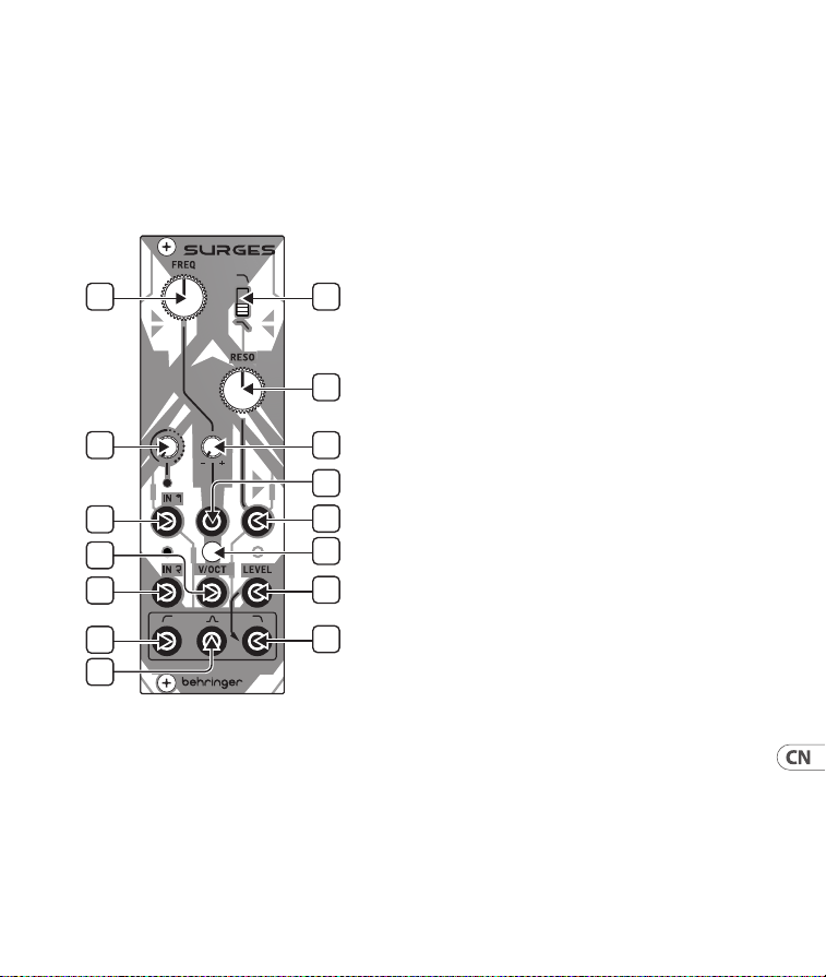
75Quick Start Guide74 SURGES
SURGES 控制
1
4
6
10
13
14
11
2
3
5
9
7
8
12
15
(CN) 控制
1. FREQ – 使用此控制设置 SURGES 截止
频率。
2. SLOPE – 使用此开关设置低通和带
通滤波器的截止斜率; 向上为 24 dB/
八度, 向下为 12 dB/ 八度。
3. RESO – 使用此控制设置谐振级别,
强调截止点周围的一段频率带。 在极
端设置下, SURGES 将自振。
4. INPUT 1 GAIN – 使用此控制设置输入
一的增益。 较高的设置将导致信号被
过度驱动。
5. FREQ CV ATTENUVERTER – 使用此控制
设置电压控制频率的级别, 并在需要
时进行反转。
6. IN 1 – 使用此 3.5 毫米 TS 插孔输入
可通过控制 4 调整电平/过载的音频
信号。 上方的 LED 在有信号时亮起,
并随着增益的增加而变得更亮。
7. FREQ CV IN – 使用此 3.5 毫米 TS 插孔通
过衰减器 5 从外部 CV 源控制 SURGES
的截止频率。 范围是 -8 V 至 +8 V。
8. RESO CV IN – 使用此 3.5 毫米 TS 插孔通
过外部 CV 源控制 SURGES 的谐振级别。
范围是 -8 V 至 +8 V。
9. V/OCT CALIBRATION – 如果需要校准
电压/八度跟踪, 请移除此盖板, 并使
用适当的螺丝刀调整下面的微调器。
请注意, 这应仅由熟练人员执行。 参见
下方的校准说明。
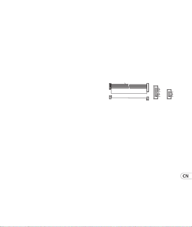
77Quick Start Guide76 SURGES
10. IN 2 – 使用此 3.5 毫米 TS 插孔将第二
个干净信号输入 SURGES。 上方的 LED
在有信号时亮起。 两个输入可以同
时使用。
11. V/OCT – 使用此 3.5 毫米 TS 插孔跟踪
1 伏/八度的截止频率。 范围是 -3 V
至 +7 V 。
12. LOW PASS LEVEL – 使用此 3.5 毫米 TS
插孔控制外部 CV 源的低通输出的
电平。 范围是 0 V (无输出), 通过 +5 V
(单元) 至 +7 V (压缩)。 如果没有使用
外部电压, 则内部应用 +7 V 。
13. HIGH PASS OUT – 使用此 3.5 毫米 TS
插孔访问高通滤波器的输出
14. BAND PASS OUT – 使用此 3.5 毫米 TS
插孔访问带通滤波器的输出。
15. LOW PASS OUT – 使用此 3.5 毫米 TS
插孔访问低通滤波器的输出。
所有输出可以同时使用。
校准
1. 断开除连接到 V/OCT 输入 (11) 的适当校
准的 1 伏/八度键盘之外的所有外部 CV
控制器。
2. 将 Freq 控制 (1) 设置为大致处于中间
位置, 将 Reso 控制 (3) 设置为最大。
3. 通过耳朵或使用调音器, 调整微调器
(9), 直到演奏相隔一个八度的音符在低
通输出 (15)上产生正确调音的八度输出。
电源连接
该模块配备了连接到标准 Eurorack 电源系
统所需的电源线。 按照这些步骤将模块连
接到您的 Eurorack 案例。
1. 关闭电源或机架外壳电源并断开电源
电缆。
2. 将电源线上的 16 针连接器插入电源或
机架盒上的插座中。 连接器有一个选
项卡, 该选项卡将与插座中的间隙对齐,
因此不能错误地插入该选项卡。 如果电
源没有钥匙插座, 请务必将引脚 1 (-12 V)
定向到电缆上的红色条纹上。
3. 将 10 针连接器插入模块背面的插座中。
连接器有一个选项卡, 该选项卡将与插
座对齐以获得正确的方向。
4. 电源线的两端牢固连接后, 您可以在情
况下安装模块并打开电源。
HOT USED
Red Stripe
200 mm ± 10
15 16
21
P2P1
2
10 9
1
Connect end P1 to the module socket
Connect end P2 to the power supply
+ 12V
- 12V
GROUND
+ 12V
- 12V
GROUND
SURGES 控制

79Quick Start Guide78 SURGES
安装
必要的螺丝包含在用于安装在欧洲拉克箱
中的模块中。 安装前连接电源线。
根据机架外壳的不同, 可能会有一系列固
定孔, 沿着机箱的长度间隔 2 HP, 或允许单
个螺纹板沿外壳长度滑动的轨道。 自由移
动的螺纹板允许模块的精确定位, 但在连
接螺丝之前, 每个板应定位在与模块安装
孔的大致关系中。
将模块与 Eurorack 导轨对立, 以便每个安
装孔与螺纹导轨或螺纹板对齐。 将螺丝
部分连接以开始, 这将允许在调整它们
时对定位进行小调整。 确定最终位置后,
拧紧螺丝。
Specications
Inputs
Audio Input 1
3.5 mm TS jack,
impedance 100 kΩ
Audio Input 2
3.5 mm TS jack,
impedance 100 kΩ
Frequency CV
3.5 mm TS jack,
range -8 V to +8 V
Resonance CV
3.5 mm TS jack,
range -8 V to +8 V
Volt/octave
3.5 mm TS jack,
range -3 V to +7 V
LPF output level
3.5 mm TS jack
range 0 V to +7 V
Outputs
High Pass Filter
3.5 mm TS jack,
impedance 1 kΩ
Band Pass Filter
3.5 mm TS jack,
impedance 1 kΩ
Low Pass Filter
3.5 mm TS jack,
impedance 1 kΩ
Controls
Controls
Frequency
Resonance
Frequency CV
Attenuverter
Input 1 Gain
Switches Filter Slope
Power Requirements
Power supply Eurorack
Current draw
35 mA on both
+12 V and
-12 V rails
Physical
Operating
Temperature
5° C - 45° C
(41° F - 113° F)
Dimensions
(H x W x D)
129 x 40 x 41 mm
(5.06 x 1.59 x 1.62")
Rack units 8 HP
Weight 0.19 lb
81Quick Start Guide80 SURGES
技术参数
输入
音频输入 1
3.5 mm TS 插孔,
阻抗 100 kΩ
音频输入 2
3.5 mm TS 插孔,
阻抗 100 kΩ
频率简历
3.5 mm TS 插孔,
范围 -8 V 至 +8 V
共振简历
3.5 mm TS 插孔,
范围 -8 V 至 +8 V
伏特/倍频程
3.5 mm TS 插孔,
范围 -3 V 至 +7 V
LPF 输出电平
3.5 mm TS 插孔
范围 0 V 至 +7 V
输出
高通滤波器
3.5 毫米 TS 插孔,
阻抗 1 kΩ
带通滤波器
3.5 毫米 TS 插孔,
阻抗 1 kΩ
低通滤波器
3.5 毫米 TS 插孔,
阻抗 1 kΩ
控制
控制
频率
共鸣
频率 CV 衰减器
输入 1 增益
开关 过滤器斜率
电源要求
电源 欧式机架
电流消耗
+12 V 和 -12 V
电源轨上均为
35 mA
物理的
工作温度
5° C - 45° C
(41° F - 113°F)
尺寸
(高 x 宽 x 深)
129 x 40 x 41 mm
(5.06 x 1.59 x 1.62")
机架单元
8 HP
重量
0.19 lb
83Quick Start Guide82 SURGES
FEDERAL COMMUNICATIONS
COMMISSION COMPLIANCE
INFORMATION
Responsible Party Name: Music Tribe
Commercial NV Inc.
Address: 122 E. 42nd St.1,
8th Floor NY,
NY 10168,
United States
Email Address: [email protected]
SURGES
This equipment has been tested and found to comply
with the limits for a Class B digital device, pursuant
to part 15 of the FCC Rules. These limits are designed
to provide reasonable protection against harmful
interference in a residential installation. This equipment
generates, uses and can radiate radio frequency energy
and, if not installed and used in accordance with the
instructions, may cause harmful interference to radio
communications. However, there is no guarantee that
interference will not occur in a particular installation. If
this equipment does cause harmful interference to radio
or television reception, which can be determined by
turning the equipment o and on, the user is encouraged
to try to correct the interference by one or more of the
following measures:
• Reorient or relocate the receiving antenna.
• Increase the separation between the equipment
and receiver.
• Connect the equipment into an outlet on a
circuit dierent from that to which the receiver is
connected.
• Consult the dealer or an experienced radio/TV
technician for help.
This equipment complies with Part 15 of the FCC rules.
Operation is subject to the following two conditions:
(1) this device may not cause harmful interference, and
(2) this device must accept any interference received,
including interference that may cause undesired operation.
Behringer
Important information:
Changes or modications to the equipment not expressly
approved by Music Tribe can void the user’s authority to
use the equipment.
Hereby, Music Tribe declares that this product is in
compliance with Directive 2014/30/EU, Directive
2011/65/EU and Amendment 2015/863/EU, Directive
2012/19/EU, Regulation 519/2012 REACH SVHC and
Directive 1907/2006/EC.
Full text of EU DoC is available at https://community.
musictribe.com/
EU Representative: Music Tribe Brands DK A/S
Address: Gammel Strand 44, DK-1202
København K, Denmark
UK Representative: Music Tribe Brands UK Ltd.
Address: 8th Floor, 20 Farringdon Street London EC4A
4AB, United Kingdom
Correct disposal of this product: This symbol
indicates that this product must not be
disposed of with household waste, according
to the WEEE Directive (2012/19/EU) and
your national law. This product should be
taken to a collection center licensed for the recycling
of waste electrical and electronic equipment (EEE). The
mishandling of this type of waste could have a possible
negative impact on the environment and human health
due to potentially hazardous substances that are
generally associated with EEE. At the same time, your
cooperation in the correct disposal of this product will
contribute to the ecient use of natural resources. For
more information about where you can take your waste
equipment for recycling, please contact your local city
oce, or your household waste collection service.
SURGES
85Quick Start Guide84 SURGES

We Hear You