Quick Start Guide
SYSTEM 100 Series
140 DUAL ENVELOPE/ LFO
Legendary Analog Dual Envelope/LFO Module for Eurorack
V 5.0
2 140 DUAL ENVELOPE/ LFO Quick Start Guide 3
7. Verwenden Sie nur
spezizierte Wagen,
Ständer, Stative,
Halterungen oder Tische.
Achten Sie darauf, beim
Bewegen der Wagen-
Geräte-Kombination ein
Umkippen zu vermeiden.
8. Vermeiden Sie die Installation in beengten Räumen
wie Bücherregalen.
9. Nicht in der Nähe von oenen Flammenquellen
platzieren, wie brennende Kerzen.
10. Betriebstemperaturbereich von 5° bis 45°C
(41° bis 113°F).
HAFTUNGSAUSSCHLUSS
Music Tribe übernimmt keine Haftung für Verluste,
die Personen entstanden sind, die sich ganz oder
teilweise auf hier enthaltene Beschreibungen,
Fotos oder Aussagen verlassen haben. Technische Daten,
Erscheinungsbild und andere Informationen können
ohne vorherige Ankündigung geändert werden. Alle
Warenzeichen sind Eigentum der jeweiligen Inhaber.
Midas, Klark Teknik, Lab Gruppen, Lake, Tannoy,
Turbosound, TC Electronic, TC Helicon, Behringer, Bugera,
Aston Microphones und Coolaudio sind Warenzeichen
oder eingetragene Warenzeichen der Music Tribe Global
Brands Ltd. © Music Tribe Global Brands Ltd. 2024 Alle
Rechte vorbehalten.
BESCHRÄNKTE GARANTIE
Die geltenden Garantiebedingungen und zusätzliche
Informationen bezüglich der von Music Tribe gewährten
beschränkten Garantie nden Sie online unter
community.musictribe.com/support.
(PT) Instruções de Seguranç
Importantes
1. Por favor, leia e siga todas as instruções.
2. Mantenha o aparelho longe da água, exceto para
produtos destinados ao uso externo.
3. Limpe apenas com um pano seco.
4. Não bloqueie nenhuma abertura de ventilação. Instale
de acordo com as instruções do fabricante.
5. Não instale próximo a fontes de calor, como
radiadores, grelhas de calor, fogões ou outros aparelhos
(incluindo amplicadores) que gerem calor.
6. Use apenas acessórios especicados pelo fabricante.
7. Use apenas carrinhos,
suportes, tripés, suportes
ou mesas especicados.
Tenha cuidado para evitar
tombamentos ao mover a
combinação carrinho/
aparelho.
8. Evite instalar em espaços connados, como estantes.
9. Não coloque perto de fontes de chama nua,
como velas acesas.
10. Intervalo de temperatura de operação de 5° a 45°C
(41° a 113° F).
LEGAL RENUNCIANTE
O Music Tribe não se responsabiliza por perda
alguma que possa ser sofrida por qualquer pessoa
que dependa, seja de maneira completa ou parcial,
de qualquer descrição, fotograa, ou declaração
aqui contidas. Dados técnicos, aparências e outras
informações estão sujeitas a modicações sem aviso
prévio. Todas as marcas são propriedade de seus
respectivos donos. Midas, Klark Teknik, Lab Gruppen,
Lake, Tannoy, Turbosound, TC Electronic, TC Helicon,
Behringer, Bugera, Aston Microphones e Coolaudio
são marcas ou marcas registradas do Music Tribe
Global Brands Ltd. © Music Tribe Global Brands Ltd.
2024 Todos direitos reservados.
GARANTIA LIMITADA
Para obter os termos de garantia aplicáveis e condições e
informações adicionais a respeito da garantia limitada do
Music Tribe, favor vericar detalhes na íntegra através do
website community.musictribe.com/support.
(IT) Istruzioni di sicurezza importanti
1. Per favore, leggere e seguire tutte le istruzioni.
2. Mantenere l'apparecchio lontano dall'acqua, tranne
per i prodotti destinati all'uso all'aperto.
3. Pulire solo con un panno asciutto.
4. Non ostruire alcuna apertura di ventilazione. Installare
in conformità alle istruzioni del produttore.
5. Non installare vicino a fonti di calore come
termosifoni, bocchette di calore, fornelli o altri apparecchi
(compresi gli amplicatori) che producono calore.
6. Utilizzare solo accessori specicati dal produttore.
7. Usare solo carrelli,
supporti, treppiedi, stae
o tavoli specicati. Prestare
attenzione per evitare il
ribaltamento durante lo
spostamento della
combinazione carrello/
apparecchio.
8. Evitare l'installazione in spazi connati come librerie.
9. Non posizionare vicino a fonti di amma nude,
come candele accese.
10. Intervallo di temperatura di funzionamento da
5° a 45°C (41° a 113°F).
DISCLAIMER LEGALE
Music Tribe non si assume alcuna responsabilità per
eventuali danni che possono essere subiti da chiunque
si adi in tutto o in parte a qualsiasi descrizione,
fotograa o dichiarazione contenuta qui. Speciche
tecniche, aspetti e altre informazioni sono soggette
a modiche senza preavviso. Tutti i marchi sono di
proprietà dei rispettivi titolari. Midas, Klark Teknik,
Lab Gruppen, Lake, Tannoy, Turbosound, TC Electronic,
TC Helicon, Behringer, Bugera, Aston Microphones e
Coolaudio sono marchi o marchi registrati di Music Tribe
Global Brands Ltd. © Music Tribe Global Brands Ltd.
2024 Tutti i diritti riservati.
GARANZIA LIMITATA
Per i termini e le condizioni di garanzia applicabili e le
informazioni aggiuntive relative alla garanzia limitata
di Music Tribe, consultare online i dettagli completi su
community.musictribe.com/support.
(NL) Belangrijke
veiligheidsvoorschriften
1. Lees alsjeblieft alle instructies en volg deze op.
2. Houd het apparaat uit de buurt van water, behalve
voor producten die bedoeld zijn voor buitengebruik.
3. Reinig alleen met een droge doek.
4. Blokker geen ventilatieopeningen. Installeer volgens
de instructies van de fabrikant.
5. Installeer niet in de buurt van warmtebronnen
zoals radiatoren, warmte registers, fornuizen of andere
apparaten (inclusief versterkers) die warmte produceren.
6. Gebruik alleen accessoires die door de fabrikant
zijn gespeciceerd.
7. Gebruik alleen
gespeciceerde karren,
standaards, statieven,
beugels of tafels. Wees
voorzichtig om kantelen te
voorkomen bij het
verplaatsen van de kar/
apparaatcombinatie.
8. Vermijd installatie in afgesloten ruimtes
zoals boekenkasten.
9. Plaats niet in de buurt van naakte vlambronnen,
zoals brandende kaarsen.
10. Bedrijfstemperatuurbereik
van 5° tot 45°C (41° tot 113°F).
WETTELIJKE ONTKENNING
Music Tribe aanvaardt geen aansprakelijkheid voor enig
verlies dat kan worden geleden door een persoon die
geheel of gedeeltelijk vertrouwt op enige beschrijving,
foto of verklaring hierin. Technische specicaties,
verschijningen en andere informatie kunnen zonder
voorafgaande kennisgeving worden gewijzigd. Alle
handelsmerken zijn eigendom van hun respectievelijke
eigenaren. Midas, Klark Teknik, Lab Gruppen, Lake,
Tannoy, Turbosound, TC Electronic, TC Helicon,
Behringer, Bugera, Aston Microphones en Coolaudio
(EN) Safety Instruction
1. Please read and follow all instructions.
2. Keep the apparatus away from water, except for
outdoor products.
3. Clean only with a dry cloth.
4. Do not block any ventilation openings. Install in
accordance with the manufacturer’s instructions.
5. Do not install near any heat sources such as radiators,
heat registers, stoves or other apparatus (including
ampliers) that produce heat.
6. Use only attachments/accessories specied by
the manufacturer.
7. Use only specied
carts, stands, tripods,
brackets, or tables. Use
caution to prevent tip-over
when moving the cart/
apparatus combination.
8. Avoid installing in conned spaces like bookcases.
9. Do not place near naked ame sources, such as
lighted candles.
10. Operating temperature range 5° to 45°C
(41° to 113°F).
LEGAL DISCLAIMER
Music Tribe accepts no liability for any loss which may
be suered by any person who relies either wholly or in
part upon any description, photograph, or statement
contained herein. Technical specications, appearances
and other information are subject to change without
notice. All trademarks are the property of their
respective owners. Midas, Klark Teknik, Lab Gruppen,
Lake, Tannoy, Turbosound, TC Electronic, TC Helicon,
Behringer, Bugera, Aston Microphones and Coolaudio
are trademarks or registered trademarks of Music
Tribe Global Brands Ltd. © Music Tribe Global Brands
Ltd. 2024 All rights reserved.
LIMITED WARRANTY
For the applicable warranty terms and conditions
and additional information regarding Music Tribe’s
Limited Warranty, please see complete details online at
community.musictribe.com/support.
(ES) Instrucción de seguridad
1. Por favor, lea y siga todas las instrucciones.
2. Mantenga el aparato alejado del agua, excepto para
productos destinados al uso en exteriores.
3. Limpie solo con un paño seco.
4. No bloquee ninguna abertura de ventilación. Instale
de acuerdo con las instrucciones del fabricante.
5. No instale cerca de fuentes de calor como radiadores,
registros de calor, estufas u otros aparatos (incluyendo
amplicadores) que generen calor.
6. Utilice solo accesorios especicados por el fabricante.
7. Use solo carros,
soportes, trípodes,
soportes o mesas
especicados. Tenga
precaución para evitar el
vuelco al mover la
combinación carro/
aparato.
8. Evite la instalación en espacios connados
como estanterías.
9. No colocar cerca de fuentes de llama desnuda,
como velas encendidas.
10. Rango de temperatura de funcionamiento de
5° a 45°C (41° a 113° F).
NEGACIÓN LEGAL
Music Tribe no admite ningún tipo de responsabilidad
por cualquier daño o pérdida que pudiera sufrir
cualquier persona por conar total o parcialmente en la
descripciones, fotografías o armaciones contenidas en
este documento. Las especicaciones técnicas, imágenes
y otras informaciones contenidas en este documento
están sujetas a modicaciones sin previo aviso. Todas las
marcas comerciales que aparecen aquí son propiedad
de sus respectivos dueños. Midas, Klark Teknik,
Lab Gruppen, Lake, Tannoy, Turbosound, TC Electronic,
TC Helicon, Behringer, Bugera, Aston Microphones y
Coolaudio son marcas comerciales o marcas registradas
de Music Tribe Global Brands Ltd. © Music Tribe Global
Brands Ltd. 2024 Reservados todos los derechos.
GARANTÍA LIMITADA
Si quiere conocer los detalles y condiciones aplicables
de la garantía así como información adicional sobre
la Garantía limitada de Music Tribe, consulte online
toda la información en la web community.musictribe.
com/support.
(FR) Consignes de sécurité
1. Veuillez lire et suivre toutes les instructions.
2. Gardez l'appareil éloigné de l'eau, sauf pour les
produits destinés à une utilisation en extérieur.
3. Nettoyez uniquement avec un chion sec.
4. Ne bloquez aucune ouverture de ventilation. Installez
conformément aux instructions du fabricant.
5. N'installez pas près de sources de chaleur telles
que radiateurs, grilles de chaleur, cuisinières ou autres
appareils (y compris les amplicateurs) qui produisent de
la chaleur.
6. Utilisez uniquement les accessoires spéciés par
le fabricant.
7. Utilisez uniquement
des chariots, des supports,
des trépieds, des supports
ou des tables spéciés.
Faites attention pour éviter
le renversement lors du
déplacement de la
combinaison chariot/
appareil.
8. Évitez l'installation dans des espaces connés comme
les bibliothèques.
9. Ne pas placer près de sources de amme nue,
telles que des bougies allumées.
10. Plage de température de fonctionnement de
5° à 45°C (41° à 113°F)
DÉNI LÉGAL
Music Tribe ne peut être tenu pour responsable pour
toute perte pouvant être subie par toute personne
se ant en partie ou en totalité à toute description,
photographie ou armation contenue dans ce
document. Les caractéristiques, l’apparence et d’autres
informations peuvent faire l’objet de modications
sans notication. Toutes les marques appartiennent
à leurs propriétaires respectifs. Midas, Klark Teknik,
Lab Gruppen, Lake, Tannoy, Turbosound, TC Electronic,
TC Helicon, Behringer, Bugera, Aston Microphones et
Coolaudio sont des marques ou marques déposées de
Music Tribe Global Brands Ltd. © Music Tribe Global
Brands Ltd. 2024 Tous droits réservés.
GARANTIE LIMITÉE
Pour connaître les termes et conditions de
garantie applicables, ainsi que les informations
supplémentaires et détaillées sur la Garantie
Limitée de Music Tribe, consultez le site Internet
community.musictribe.com/support.
(DE) Wichtige Sicherheitshinweise
1. Bitte lesen Sie alle Anweisungen sorgfältig durch und
befolgen Sie diese.
2. Halten Sie das Gerät von Wasser fern, außer für
Produkte, die für den Außeneinsatz vorgesehen sind.
3. Reinigen Sie es nur mit einem trockenen Tuch.
4.
Blockieren Sie keine Belüftungsönungen. Installieren
Sie gemäß den Anweisungen des Herstellers.
5. Installieren Sie nicht in der Nähe von Wärmequellen
wie Heizkörpern, Heizregistern, Öfen oder anderen
Geräten (einschließlich Verstärkern), die Wärme erzeugen.
6. Verwenden Sie nur Zubehörteile, die vom Hersteller
angegeben sind.
4 140 DUAL ENVELOPE/ LFO Quick Start Guide 5
(CN)
安全须知
1. 请阅读, 保存, 遵守所有的说明, 注意所
有的警示。
2. 请勿在靠近水的地方使用本产品。
3. 请用干布清洁本产品。
4. 请只使用厂家指定的附属设备和配件。
不要堵塞任何通风口。按照制造商的说明
进行安装。
5. 请只使用厂家指
定的或随货销售的
手推车, 架子, 三角
架, 支架和桌子等。
若使用手推车来搬
运设备, 请注意安
全放置设备, 以避
免手推车和设备倾
倒而受伤。
6. 请勿安装在密闭空间, 如书柜或类似
装置。
7. 请勿将本产品安装在热源附近, 如暖气
片, 炉子或其它产生热量的设备 (包括功放
器)。 产品上不要放置裸露的火焰源, 如点
燃的蜡烛。
8. 如果液体流入或异物落入设备内,
设备遭雨淋或受潮, 设备不 能正常运作或
被摔坏等, 设备受损需进行维修时, 所有维
修均须由 合格的维修人员进行维修。
法律声明
对于任何因在此说明书提到的全部或部份
描述、 图片或声明而造成的损失, Music Tribe
不负任何责任。 技术参数和外观若有更改,
恕不另行通知。 所有的商标均为其各自所
有者的财产。
Midas, Klark Teknik, Lab Gruppen,
Lake, Tannoy, Turbosound, TC Electronic, TC Helicon,
Behringer, Bugera, Aston Microphones
和 Coolaudio
是 Music Tribe Global Brands Ltd. 公司的商标
或注册商标。 © Music Tribe Global Brands Ltd.
2024 版权所有。
保修条款
有关音乐集团保修的适用条款及其它相关
信息, 请登陆 community.musictribe.com/support
网站查看完整的详细信息。
zijn handelsmerken of gedeponeerde handelsmerken
van Music Tribe Global Brands Ltd. © Music Tribe Global
Brands Ltd. 2024 Alle rechten voorbehouden.
BEPERKTE GARANTIE
Voor de toepasselijke garantievoorwaarden en
aanvullende informatie met betrekking tot de beperkte
garantie van Music Tribe, zie de volledige details online
op community.musictribe.com/support.
(SE) Viktiga säkerhetsanvisningar
1. Vänligen läs och följ alla instruktioner noggrant.
2. Håll apparaten borta från vatten, förutom
för utomhusprodukter.
3. Rengör endast med en torr trasa.
4. Blockera inte några ventilationsöppningar.
Installera enligt tillverkarens anvisningar.
5. Installera inte nära några värmekällor som element,
värmeregistrar, spisar eller andra apparater (inklusive
förstärkare) som genererar värme.
6. Använd endast tillbehör som anges av tillverkaren.
7. Använd endast
specicerade vagnar, ställ,
stativ, fästen eller bord. Var
försiktig för att undvika att
vagnen/
apparatkombinationen
tippar när den yttas.
8. Undvik installation i
trånga utrymmen som bokhyllor.
9. Placera inte nära öppen låga, såsom tända ljus.
10. Driftstemperaturområde 5° till 45°C (41° till 113°F).
FRISKRIVNINGSKLAUSUL
Music Tribe tar inget ansvar för någon förlust som kan
drabbas av någon person som helt eller delvis förlitar
sig på någon beskrivning, fotogra eller uttalande som
nns här. Tekniska specikationer, utseenden och annan
information kan ändras utan föregående meddelande.
Alla varumärken tillhör respektive ägare. Midas,
Klark Teknik, Lab Gruppen, Lake, Tannoy, Turbosound,
TC Electronic, TC Helicon, Behringer, Bugera, Aston
Microphones och Coolaudio är varumärken eller
registrerade varumärken som tillhör Music Tribe Global
Brands Ltd. © Music Tribe Global Brands Ltd. 2024 Alla
Rättigheter reserverade.
BEGRÄNSAD GARANTI
För tillämpliga garantivillkor och ytterligare information
om Music Tribes begränsade garanti, se fullständig
information online på community.musictribe.
com/support.
(PL) Ważne informacje o
bezpieczeństwie
1. Proszę przeczytać i ścisłe przestrzegać
wszystkich instrukcji.
2. Trzymaj urządzenie z dala od wody, z wyjątkiem
produktów przeznaczonych do użytku na zewnątrz.
3. Czyść tylko suchą szmatką.
4. Nie blokuj żadnych otworów wentylacyjnych.
Instaluj zgodnie z instrukcjami producenta.
5. Nie instaluj w pobliżu źródeł ciepła, takich jak
grzejniki, rejestratory ciepła, kuchenki lub inne urządzenia
(w tym wzmacniacze), które generują ciepło.
6. Używaj tylko akcesoriów określonych
przez producenta.
7. Używaj tylko
określonych wózków,
stojaków, statywów,
uchwytów lub stołów.
Uważaj, aby zapobiec
przewróceniu się wózka/
aparatu podczas
przemieszczania.
8. Unikaj instalacji w ciasnych miejscach, takich jak
regały na książki.
9. Nie umieszczaj w pobliżu źródeł otwartego ognia,
takich jak zapalone świeczki.
10. Zakres temperatury pracy od 5° do 45°C
(41° do 113°F).
ZASTRZEŻENIA PRAWNE
Music Tribe nie ponosi odpowiedzialności za
jakiekolwiek straty, które mogą ponieść osoby, które
polegają w całości lub w części na jakimkolwiek opisie,
fotograi lub oświadczeniu zawartym w niniejszym
dokumencie. Specykacje techniczne, wygląd i inne
informacje mogą ulec zmianie bez powiadomienia.
Wszystkie znaki towarowe są własnością ich
odpowiednich właścicieli. Midas, Klark Teknik,
Lab Gruppen, Lake, Tannoy, Turbosound, TC Electronic,
TC Helicon, Behringer, Bugera, Aston Microphones i
Coolaudio są znakami towarowymi lub zastrzeżonymi
znakami towarowymi rmy Music Tribe Global Brands
Ltd. © Music Tribe Global Brands Ltd. 2024 Wszystkie
prawa zastrzeżone.
OGRANICZONA GWARANCJA
Aby zapoznać się z obowiązującymi warunkami
gwarancji i dodatkowymi informacjami dotyczącymi
ograniczonej gwarancji Music Tribe, zapoznaj się ze
wszystkimi szczegółami w trybie online pod adresem
community.musictribe.com/support.
(JP)
安全指示
1. す べ て の 指 示 を 読 ん で 、従 っ て く だ
さい。
2. 屋 外 の 製 品 を 除 き 、機 器 を 水 か ら 遠 ざ
け てください 。
3. 乾いた布でのみ清掃してください。
4. 通気口を塞がないでください。
メーカーの指示に従ってインストールして
ください。
5. 暖 房 器 、ヒ ー ト レ ジ ス タ ー 、ス ト ー ブ な
どの発熱機器(アンプを含む)の近くには
取り付けないでください。
6. メーカーが指定したアタッチメント/
アクセサリーのみ使用してください。
7. 指定されたカー
ト、スタンド、三
脚 、ブ ラ ケ ッ ト 、ま
たはテーブルの み
使 用してください 。
カート/ 機 器の組み
合わせを移動する
際 に は 、転 倒 を 防 ぐ
よう注意してください。
8. 書棚などの密閉された空間には設置し
ないでください。
9. 裸火のような火の元の近くに置かない
でください。
10. 動作温度範囲は摂氏 5 度から 45
度 (華氏
41 度から 113 度) です。
法的放棄
こ こ に 含 ま れ る 記 述 、写 真 、意 見 の 全
体 ま た は 一 部 に 依 拠 し て 、い か な る 人 が
損害を生じさせた場合にも、Music Tribe
は 一 切 の 賠 償 責 任 を 負 い ま せ ん 。技 術
仕様、外観およびその他の情報は予告
な く 変 更 に な る 場 合 が あ り ま す。商 標
はすべて、それぞれの所有者に帰属し
ます。Midas、Klark Teknik、Lab Gruppen、
Lake、Tannoy、Turbosound、TC Electronic、
TC Helicon、Behringer、Bugera、
Aston Microphones
および Coolaudio は Music Tribe Global Brands
Ltd.
の商標または登録商標です。© Music
Tribe Global Brands Ltd. 2024
無断転用禁止。
限定保証
適用される保証条件と Music Tribe の限定
保 証 に 関 す る 概 要 に つ い て は 、オ ン ラ イ
ン上 community.musictribe.com/support にて詳
細をご確認ください 。

6 140 DUAL ENVELOPE/ LFO Quick Start Guide 7
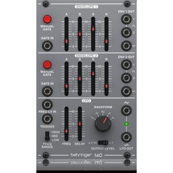
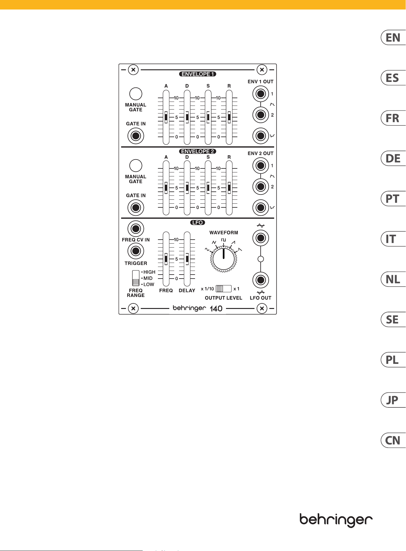
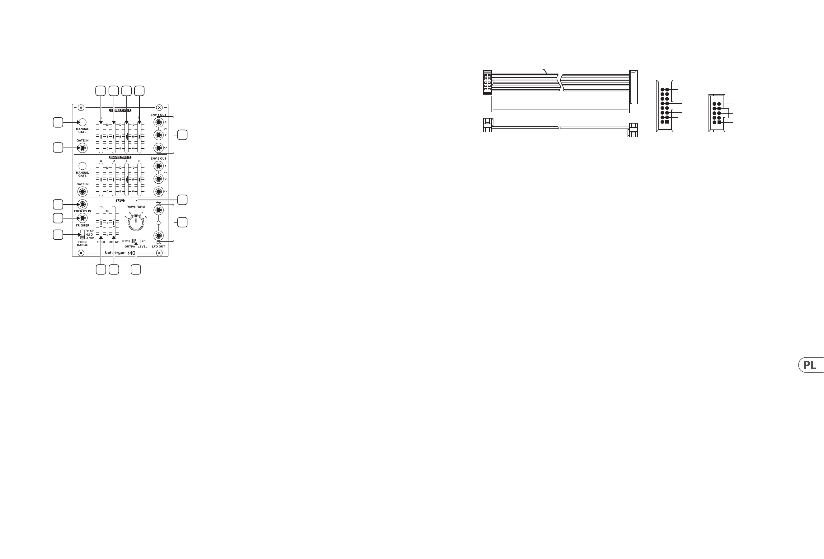
140 DUAL ENVELOPE/ LFO Controls
(EN) Controls
2
3
4
5
6
7
8
9
1
10
11
12
13
14
15
1. MANUAL GATE – Press and hold to start the envelope cycle.
2. EXT GATE – Connect a gate signal to control the envelope cycle.
3. ATTACK TIME – Adjusts the rate at which the envelope reaches its
peakvoltage.
4. DECAY TIME – Adjusts the rate at which the envelope decays from its peak
level to its designated sustain level.
5. SUSTAIN LEVEL – Controls the level at which the envelope remains after its
peak but before release, sustaining as long as the input signal is present or
the manual gate switch is held down.
6. RELEASE TIME – Controls how quickly the envelope falls after the input
signal stops or the manual gate switch is released.
7. ENV OUTPUTS – Send up to 2 positive waveforms and a negative
waveform to other modules via these output connectors.
8. FREQ RANGE – Sets the oscillating frequency range of the LFO in 3 steps.
9. FREQ – Manually sets the oscillating frequency of the LFO.
10. DELAY – Sets the time from when a trigger signal is received until the LFO
begins operating again.
11. FREQ CV IN – Accepts voltage for controlling the LFO frequency with an
external source.
12. TRIGGER – Connect a trigger signal to turn the LFO o until the end of the
trigger cycle. This works along with the Delay slider, and the LFO recovery
takes about 20 seconds. The rear panel features a jumper that can be
removed if you don’t want the LFO to be re-triggered.
13. OUTPUT LEVEL – Selects between standard or 1/10th output level for the
LFO OUT jacks.
14. WAVEFORM – Select between sine, triangle, pulse, sawtooth or reverse
sawtooth for the LFO waveform output.
15. LFO OUT – Sends the LFO output to other modules. The upper jack is non-
inverting and the lower jacks is inverting.
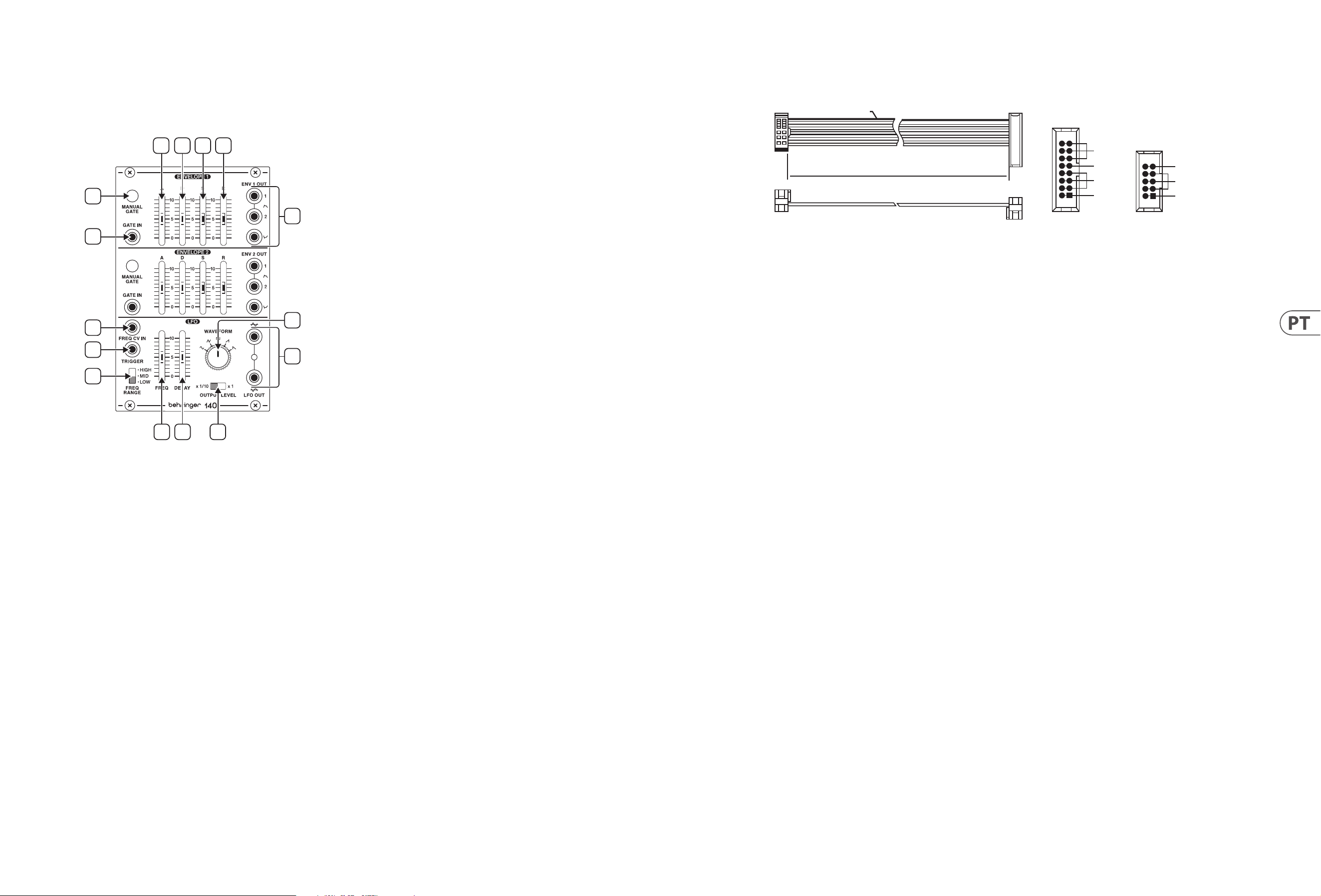
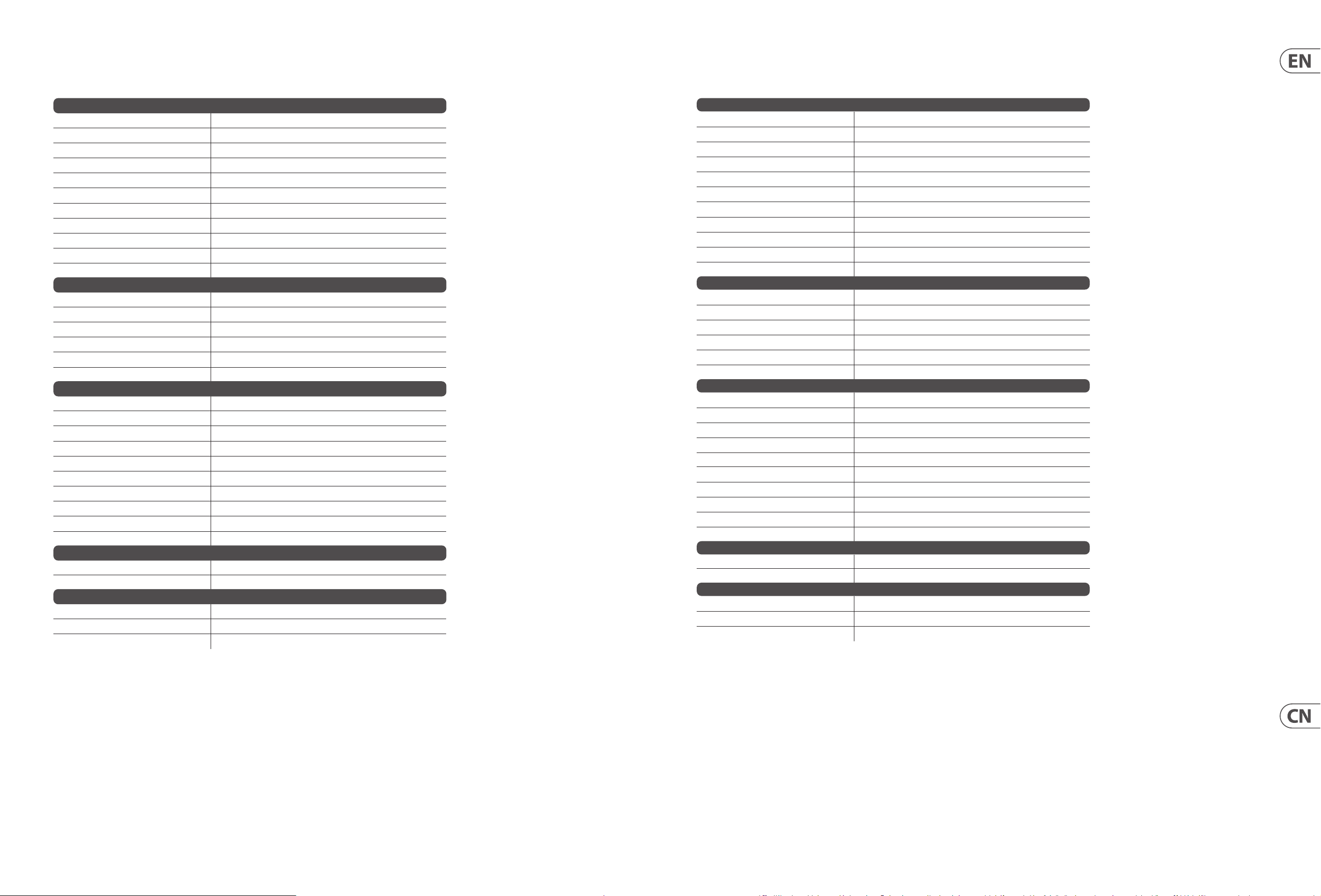
Power Connection
HOT USED
Red Stripe
200 mm ± 10
15 16
21
P2P1
2
10
9
1
Connect end P1 to the module socket
Connect end P2 to the power supply
+ 12V
- 12V
GROUND
+ 12V
- 12V
GROUND
The 140 comes with the required power cable for connecting to a standard
Eurorack power supply system. Follow these steps to connect power to the
module. It is easier to make these connections before the module has been
mounted into a rack case.
1. Turn the power supply or rack case power o and disconnect the
powercable.
2. Insert the 16-pin connector on the power cable into the socket on the
power supply or rack case. The connector has a tab that will align with the
gap in the socket, so it cannot be inserted incorrectly. If the power supply
does not have a keyed socket, be sure to orient pin 1 (-12 V) with the red
stripe on the cable.
3. Insert the 10-pin connector into the socket on the back of the module. The
connector has a tab that will align with the socket for correct orientation.
4. After both ends of the power cable have been securely attached, you may
mount the module in a case and turn on the power supply.
Installation
The necessary screws are included with the module for mounting in a Eurorack
case. Connect the power cable before mounting.
Depending on the rack case, there may be a series of xed holes spaced 2 HP
apart along the length of the case, or a track that allows individual threaded
plates to slide along the length of the case. The free-moving threaded plates
allow precise positioning of the module, but each plate should be positioned in
the approximate relation to the mounting holes in your module before attaching
the screws.
Hold the module against the Eurorack rails so that each of the mounting holes
are aligned with a threaded rail or threaded plate. Attach the screws part way
to start, which will allow small adjustments to the positioning while you get
them all aligned. After the nal position has been established, tighten the
screwsdown.

8 140 DUAL ENVELOPE/ LFO Quick Start Guide 9
140 DUAL ENVELOPE/ LFO Controles
(ES) Controles
2
3
4
5
6
7
8
9
1
10
11
12
13
14
15
1. MANUAL GATE – Mantenga pulsado para iniciar el ciclo desobres.
2. EXT GATE – Conecte una señal de puerta para controlar el ciclo de
laenvolvente.
3. ATTACK TIME – Ajusta la velocidad a la que la envolvente alcanza su
voltajemáximo.
4. DECAY TIME – Ajusta la velocidad a la que la envolvente decae desde su
nivel máximo hasta su nivel de sostenido designado.
5. SUSTAIN LEVEL – Controla el nivel en el que la envolvente permanece
después de su pico pero antes de su liberación, manteniéndose mientras
la señal de entrada esté presente o el interruptor de puerta manual se
mantenga presionado.
6. RELEASE TIME – Controla la rapidez con que cae la envolvente después
de que se detiene la señal de entrada o se suelta el interruptor de
puertamanual.
7. ENV OUTPUTS – Envíe hasta 2 formas de onda positivas y una forma de
onda negativa a otros módulos a través de estos conectores de salida.
8. FREQ RANGE – Establece el rango de frecuencia de oscilación del LFO
en3pasos.
9. FREQ – Congura manualmente la frecuencia de oscilación del LFO.
10. DELAY – Establece el tiempo desde que se recibe una señal de disparo
hasta que el LFO comienza a funcionar nuevamente.
11. FREQ CV IN – Acepta voltaje para controlar la frecuencia del LFO con una
fuente externa.
12. TRIGGER – Conecte una señal de disparo para apagar el LFO hasta el nal
del ciclo de disparo. Esto funciona junto con el control deslizante Delay, y la
recuperación del LFO tarda unos 20 segundos. El panel trasero cuenta con
un puente que se puede quitar si no desea que se vuelva a activar el LFO.
13. OUTPUT LEVEL – Selecciona entre nivel de salida estándar o 1/10 para las
tomas LFO OUT.
14. WAVEFORM – Seleccione entre seno, triángulo, pulso, diente de sierra o
diente de sierra inverso para la salida de la forma de onda del LFO.
15. LFO OUT – Envía la salida LFO a otros módulos. La toma superior no se
invierte y las tomas inferiores se invierten.
Conexión Eléctrica
HOT USED
Red Stripe
200 mm ± 10
15 16
21
P2P1
2
10
9
1
Connect end P1 to the module socket
Connect end P2 to the power supply
+ 12V
- 12V
GROUND
+ 12V
- 12V
GROUND
El 140 viene con el cable de alimentación necesario para conectarse a un sistema
de suministro de energía Eurorack estándar. Siga estos pasos para conectar la
alimentación al módulo. Es más fácil realizar estas conexiones antes de que el
módulo se ha montado en una caja de rack.
1. Apague la fuente de alimentación o la caja del bastidor y desconecte el
cable de alimentación.
2. Inserte el conector de 16 clavijas del cable de alimentación en la toma de
la fuente de alimentación o en la caja del bastidor. El conector tiene una
pestaña que se alineará con el espacio en el zócalo, por lo que no se puede
insertar incorrectamente. Si la fuente de alimentación no tiene un enchufe
con llave, asegúrese de orientar el pin 1 (-12 V) con la raya roja del cable.
3. Inserte el conector de 10 pines en el zócalo en la parte posterior del módulo.
El conector tiene una pestaña que se alineará con el enchufe para una
orientación correcta.
4. Una vez conectados rmemente ambos extremos del cable de
alimentación, puede montar el módulo en una caja y girar en la fuente
dealimentación.
Instalación
Los tornillos necesarios se incluyen con el módulo para su montaje en una caja
Eurorack. Conecte el cable de alimentación antes del montaje.
Dependiendo de la caja del bastidor, puede haber una serie de oricios jos
separados 2 HP a lo largo de la caja, o una pista que permita que las placas
roscadas individuales se deslicen a lo largo de la caja. Las placas roscadas de
movimiento libre permiten un posicionamiento preciso del módulo, pero cada
placa debe colocarse en una relación aproximada con los oricios de montaje en
su módulo antes de colocar los tornillos.
Sostenga el módulo contra los rieles Eurorack de modo que cada uno de los
oricios de montaje queden alineados con un riel o placa roscada. Coloque los
tornillos parcialmente para comenzar, lo que permitirá pequeños ajustes en la
posición mientras los alinea todos. Una vez establecida la posición nal, apriete
los tornillos.

10 140 DUAL ENVELOPE/ LFO Quick Start Guide 11
Connexion Électrique
HOT USED
Red Stripe
200 mm ± 10
15 16
21
P2P1
2
10
9
1
Connect end P1 to the module socket
Connect end P2 to the power supply
+ 12V
- 12V
GROUND
+ 12V
- 12V
GROUND
Le 140 est livré avec le câble d’alimentation requis pour se connecter à un
système d’alimentation standard Eurorack. Suivez ces étapes pour connecter
l’alimentation au module. Il est plus facile d’eectuer ces connexions avant le
module a été monté dans un boîtier rack.
1. Mettez le bloc d’alimentation ou le boîtier de rack hors tension et
débranchez le câble d’alimentation.
2. Insérez le connecteur à 16 broches du câble d’alimentation dans la prise du
bloc d’alimentation ou du boîtier du rack. Le connecteur a une languette
qui s’alignera avec l’espace dans la prise, il ne peut donc pas être inséré de
manière incorrecte. Si le bloc d’alimentation n’a pas de prise à clé, assurez-
vous d’orienter la broche 1 (-12 V) avec la bande rouge sur le câble.
3. Insérez le connecteur à 10 broches dans la prise à l’arrière du module.
Le connecteur a une languette qui s’alignera avec la douille pour une
orientation correcte.
4. Une fois que les deux extrémités du câble d’alimentation ont été
solidement xées, vous pouvez monter le module dans un boîtier et
surl’alimentation.
Installation
Les vis nécessaires sont incluses avec le module pour le montage dans un boîtier
Eurorack. Connectez le câble d’alimentation avant le montage.
Selon le cas de rack, il peut y avoir une série de trous xes espacés de 2 HP sur
la longueur du cas, ou une piste qui permet aux plaques letées individuelles
de glisser le long de la longueur du cas. Les plaques letées à déplacement libre
permettent un positionnement précis du module, mais chaque plaque doit être
positionnée approximativement par rapport aux trous de montage de votre
module avant de xer les vis.
Maintenez le module contre les rails Eurorack de sorte que chacun des trous
de montage soit aligné avec un rail leté ou une plaque letée. Fixez les vis
partiellement pour commencer, ce qui permettra de petits ajustements au
positionnement pendant que vous les alignerez tous. Une fois la position nale
établie, serrez les vis.
140 DUAL ENVELOPE/ LFO Réglages
(FR) Réglages
2
3
4
5
6
7
8
9
1
10
11
12
13
14
15
1. MANUAL GATE – Appuyez et maintenez pour démarrer le cycle
d’enveloppes.
2. EXT GATE – Connectez un signal de porte pour contrôler le cycle
d’enveloppe.
3. ATTACK TIME – Règle la vitesse à laquelle l’enveloppe atteint sa tension
decrête.
4. DECAY TIME – Règle la vitesse à laquelle l’enveloppe décroît de son niveau
de crête à son niveau de maintien désigné.
5. SUSTAIN LEVEL – Contrôle le niveau auquel l’enveloppe reste après son pic
mais avant sa libération, en le maintenant tant que le signal d’entrée est
présent ou que l’interrupteur de porte manuel est maintenu enfoncé.
6. RELEASE TIME – Contrôle la vitesse à laquelle l’enveloppe tombe
après l’arrêt du signal d’entrée ou le relâchement du commutateur de
portemanuel.
7. ENV OUTPUTS – Envoyez jusqu’à 2 formes d’onde positives et une forme
d’onde négative à d’autres modules via ces connecteurs desortie.
8. FREQ RANGE – Règle la plage de fréquence oscillante du LFO en 3 étapes.
9. FREQ – Règle manuellement la fréquence d’oscillation du LFO.
10. DELAY – Règle le temps entre la réception d’un signal de déclenchement et
le redémarrage du LFO.
11. FREQ CV IN – Accepte la tension pour contrôler la fréquence du LFO avec
une source externe.
12. TRIGGER – Connectez un signal de déclenchement pour désactiver le LFO
jusqu’à la n du cycle de déclenchement. Cela fonctionne avec le curseur
Delay et la récupération du LFO prend environ 20 secondes. Le panneau
arrière comporte un cavalier qui peut être retiré si vous ne voulez pas que le
LFO soit re-déclenché.
13. OUTPUT LEVEL – Sélectionne entre le niveau de sortie standard ou
1/10ème pour les prises LFOOUT.
14. WAVEFORM – Sélectionnez entre sinusoïdal, triangle, impulsion, dent de
scie ou dent de scie inversée pour la sortie de forme d’onde du LFO.
15. LFO OUT – Envoie la sortie LFO à d’autres modules. La prise supérieure n’est
pas inverseuse et les prises inférieures sontinverseuses.

12 140 DUAL ENVELOPE/ LFO Quick Start Guide 13
140 DUAL ENVELOPE/ LFO Bedienelemente
(DE) Bedienelemente
2
3
4
5
6
7
8
9
1
10
11
12
13
14
15
1. MANUAL GATE – Halten Sie gedrückt, um den Hüllkurvenzyklus zu starten.
2. EXT GATE – Schließen Sie ein Gate-Signal an, um den Hüllkurvenzyklus
zusteuern.
3. ATTACK TIME – Stellt die Rate ein, mit der die Hüllkurve ihre
Spitzenspannung erreicht.
4. DECAY TIME – Passt die Rate an, mit der die Hüllkurve von ihrem
Spitzenpegel auf den festgelegten Sustain-Pegel abfällt.
5. SUSTAIN LEVEL – Steuert den Pegel, bei dem die Hüllkurve nach ihrer
Spitze, aber vor dem Loslassen verbleibt, und hält so lange an, wie das
Eingangssignal vorhanden ist oder der manuelle Gate-Schalter gedrückt
gehaltenwird.
6. RELEASE TIME – Steuert, wie schnell die Hüllkurve fällt, nachdem das
Eingangssignal gestoppt oder der manuelle Torschalter losgelassen wurde.
7. ENV OUTPUTS – Senden Sie über diese Ausgangsanschlüsse bis zu 2
positive und eine negative Wellenform an andere Module.
8. FREQ RANGE – Stellt den oszillierenden Frequenzbereich des LFO in 3
Schritten ein.
9. FREQ – Stellt die Schwingfrequenz des LFO manuell ein.
10. DELAY – Legt die Zeit vom Empfang eines Triggersignals bis zur
Wiederaufnahme des LFO fest.
11. FREQ CV IN – Akzeptiert Spannung zur Steuerung der LFO-Frequenz mit
einer externenQuelle.
12. TRIGGER – Schließen Sie ein Triggersignal an, um den LFO bis zum Ende
des Triggerzyklus auszuschalten. Dies funktioniert zusammen mit dem
Verzögerungsregler, und die LFO-Wiederherstellung dauert etwa 20
Sekunden. Auf der Rückseite bendet sich ein Jumper, der entfernt werden
kann, wenn der LFO nicht erneut ausgelöst werden soll.
13. OUTPUT LEVEL – Wählt zwischen Standard- oder 1/10 Ausgangspegel für
die LFO OUT-Buchsen.
14. WAVEFORM – Wählen Sie für die LFO-Wellenformausgabe zwischen Sinus,
Dreieck, Impuls, Sägezahn oder Rückwärtssägezahn.
15. LFO OUT – Sendet den LFO-Ausgang an andere Module. Dieobere Buchse
ist nicht invertierend und die untere Buchse istinvertierend.
Netzanschluss
HOT USED
Red Stripe
200 mm ± 10
15 16
21
P2P1
2
10
9
1
Connect end P1 to the module socket
Connect end P2 to the power supply
+ 12V
- 12V
GROUND
+ 12V
- 12V
GROUND
Der 140 wird mit dem erforderlichen Stromkabel für den Anschluss an ein
Standard-Eurorack-Stromversorgungssystem geliefert. Befolgen Sie diese
Schritte, um das Modul mit Strom zu versorgen. Es ist einfacher, diese
Verbindungen vor dem Modul herzustellen wurde in ein Rackgehäuse montiert.
1. Schalten Sie das Netzteil oder das Rackgehäuse aus und ziehen Sie das
Netzkabel ab.
2. Stecken Sie den 16-poligen Stecker am Netzkabel in die Buchse am Netzteil
oder im Rack-Gehäuse. Der Anschluss verfügt über eine Lasche, die an
der Lücke in der Buchse ausgerichtet ist, sodass sie nicht falsch eingesetzt
werden kann. Wenn das Netzteil keine Schlüsselbuchse hat, richten Sie
Pin1 (-12 V) mit dem roten Streifen am Kabel aus.
3. Stecken Sie den 10-poligen Stecker in die Buchse auf der Rückseite des
Moduls. Der Anschluss verfügt über eine Lasche, die ausgerichtet wird mit
der Buchse für die richtige Ausrichtung.
4. Nachdem beide Enden des Netzkabels fest angeschlossen wurden,
können Sie das Modul in einem Gehäuse montieren und drehen an
derStromversorgung.
Installation
Die erforderlichen Schrauben sind im Lieferumfang des Moduls für die Montage
in einem Eurorack-Gehäuse enthalten. Schließen Sie das Netzkabel vor der
Montage an.
Abhängig vom Rack-Gehäuse kann es eine Reihe von festen Löchern geben,
die entlang der Länge des Gehäuses 2 PS voneinander entfernt sind, oder eine
Schiene, mit der einzelne Gewindeplatten entlang der Länge des Gehäuses
gleiten können. Die frei beweglichen Gewindeplatten ermöglichen eine präzise
Positionierung des Moduls. Jede Platte sollte jedoch in ungefährem Verhältnis
zu den Befestigungslöchern in Ihrem Modul positioniert werden, bevor Sie die
Schrauben anbringen.
Halten Sie das Modul so gegen die Eurorack-Schienen, dass jedes der
Befestigungslöcher mit einer Gewindeschiene oder einer Gewindeplatte
ausgerichtet ist. Bringen Sie die Schrauben teilweise an, um zu beginnen.
Dadurch können Sie die Position geringfügig anpassen, während Sie alle
ausrichten. Ziehen Sie die Schrauben fest, nachdem die endgültige Position
festgelegt wurde.
14 140 DUAL ENVELOPE/ LFO Quick Start Guide 15
Conexão de Força
HOT USED
Red Stripe
200 mm ± 10
15 16
21
P2P1
2
10
9
1
Connect end P1 to the module socket
Connect end P2 to the power supply
+ 12V
- 12V
GROUND
+ 12V
- 12V
GROUND
O 140 vem com o cabo de alimentação necessário para conectar a um sistema
de fonte de alimentação Eurorack padrão. Siga estas etapas para conectar a
alimentação ao módulo. É mais fácil fazer essas conexões antes do módulo foi
montado em uma caixa de rack.
1. Desligue a fonte de alimentação ou o gabinete do rack e desconecte o cabo
de alimentação.
2. Insira o conector de 16 pinos do cabo de alimentação no soquete da fonte
de alimentação ou no gabinete do rack. O conector tem uma aba que
se alinhará com a lacuna no soquete, portanto, não pode ser inserido
incorretamente. Se a fonte de alimentação não tiver um soquete chaveado,
certique-se de orientar o pino 1 (-12 V) com a faixa vermelha no cabo.
3. Insira o conector de 10 pinos no soquete na parte traseira do módulo.
O conector tem uma guia que irá alinhar com o soquete para
orientaçãocorreta.
4. Depois que ambas as extremidades do cabo de alimentação forem
rmemente conectadas, você pode montar o módulo em uma caixa e girar
na fonte de alimentação.
Instalação
Os parafusos necessários estão incluídos com o módulo para montagem em uma
caixa Eurorack. Conecte o cabo de alimentação antes da montagem.
Dependendo da caixa do rack, pode haver uma série de orifícios xos espaçados
de 2 HP ao longo do comprimento da caixa, ou uma trilha que permite que placas
roscadas individuais deslizem ao longo do comprimento da caixa. As placas
roscadas de movimento livre permitem o posicionamento preciso do módulo,
mas cada placa deve ser posicionada em uma relação aproximada com os orifícios
de montagem em seu módulo antes de prender os parafusos.
Segure o módulo contra os trilhos Eurorack de forma que cada um dos orifícios
de montagem estejam alinhados com um trilho ou placa rosqueada. Prenda
os parafusos parcialmente para começar, o que permitirá pequenos ajustes
no posicionamento enquanto você os alinha. Após a posição nal ter sido
estabelecida, aperte os parafusos.
140 DUAL ENVELOPE/ LFO Controles
(PT) Controles
2
3
4
5
6
7
8
9
1
10
11
12
13
14
15
1. MANUAL GATE – Pressione e segure para iniciar o ciclo deenvelope.
2. EXT GATE – Conecte um sinal de portão para controlar o ciclo doenvelope.
3. ATTACK TIME – Ajusta a taxa na qual o envelope atinge sua tensão de pico.
4. DECAY TIME – Ajusta a taxa na qual o envelope decai de seu nível de pico
para seu nível de sustentação designado.
5. SUSTAIN LEVEL – Controla o nível no qual o envelope permanece após
seu pico, mas antes da liberação, sustentando enquanto o sinal de entrada
estiver presente ou a chave de gate manual for mantida pressionada.
6. RELEASE TIME – Controla a rapidez com que o envelope cai depois que o
sinal de entrada para ou a chave do gate manual é liberada.
7. ENV OUTPUTS – Envie até 2 formas de onda positivas e uma forma de onda
negativa para outros módulos por meio desses conectores de saída.
8. FREQ RANGE – Dene a faixa de frequência de oscilação do LFO
em3etapas.
9. FREQ – Dene manualmente a frequência de oscilação do LFO.
10. DELAY – Dene o tempo a partir do momento em que um sinal de disparo é
recebido até que o LFO comece a operar novamente.
11. FREQ CV IN – Aceita tensão para controlar a frequência LFO com uma
fonteexterna.
12. TRIGGER – Conecte um sinal de disparo para desligar o LFO até o nal
do ciclo de disparo. Isso funciona junto com o controle deslizante Delay e
a recuperação do LFO leva cerca de 20 segundos. O painel traseiro possui
um jumper que pode ser removido se você não quiser que o LFO seja
disparadonovamente.
13. OUTPUT LEVEL – Seleciona entre o nível de saída padrão ou 1/10 para os
conectores LFO OUT.
14. WAVEFORM – Selecione entre seno, triângulo, pulso, dente de serra ou
dente de serra reverso para a saída da forma de onda do LFO.
15. LFO OUT – Envia a saída LFO para outros módulos. O conector superior não
é invertido e os conectores inferiores sãoinvertidos.

16 140 DUAL ENVELOPE/ LFO Quick Start Guide 17
Connessione di Alimentazione
HOT USED
Red Stripe
200 mm ± 10
15 16
21
P2P1
2
10
9
1
Connect end P1 to the module socket
Connect end P2 to the power supply
+ 12V
- 12V
GROUND
+ 12V
- 12V
GROUND
Il 140 viene fornito con il cavo di alimentazione necessario per il collegamento
a un sistema di alimentazione Eurorack standard. Seguire questi passaggi per
collegare l’alimentazione al modulo. È più facile eettuare questi collegamenti
prima del modulo è stato montato in una custodia per rack.
1. Spegnere l’alimentatore o il case del rack e scollegare il cavo
dialimentazione.
2. Inserire il connettore a 16 pin del cavo di alimentazione nella presa
sull’alimentatore o sul case del rack. Il connettore ha una linguetta che si
allineerà con lo spazio nella presa, quindi non può essere inserito in modo
errato. Se l’alimentatore non dispone di una presa con chiave, assicurarsi di
orientare il pin 1 (-12 V) con la striscia rossa sul cavo.
3. Inserire il connettore a 10 pin nella presa sul retro del modulo. Il connettore
ha una linguetta che si allineerà con la presa per il corretto orientamento.
4. Dopo che entrambe le estremità del cavo di alimentazione sono state
ssate saldamente, è possibile montare il modulo in una custodia e girarlo
sull’alimentazione.
Installazione
Le viti necessarie sono incluse con il modulo per il montaggio in una custodia
Eurorack. Collegare il cavo di alimentazione prima del montaggio.
A seconda del case del rack, potrebbero esserci una serie di fori ssi distanziati
di 2 HP l’uno dall’altro lungo la lunghezza del case, o un binario che consente
alle singole piastre lettate di scorrere lungo la lunghezza del case. Le piastre
lettate a movimento libero consentono un posizionamento preciso del modulo,
ma ciascuna piastra deve essere posizionata in relazione approssimativa con i fori
di montaggio nel modulo prima di ssare le viti.
Tenere il modulo contro le guide Eurorack in modo che ciascuno dei fori
di montaggio sia allineato con una guida lettata o una piastra lettata.
Attaccare le viti in parte per iniziare, il che consentirà piccoli aggiustamenti al
posizionamento mentre le si allineano tutte. Dopo aver stabilito la posizione
nale, serrare le viti.
140 DUAL ENVELOPE/ LFO Controlli
(IT) Controlli
2
3
4
5
6
7
8
9
1
10
11
12
13
14
15
1. MANUAL GATE – Tenere premuto per avviare il ciclo dellebuste.
2. EXT GATE – Collegare un segnale di gate per controllare il ciclo diinviluppo.
3. ATTACK TIME – Regola la velocità con cui l’inviluppo raggiunge la sua
tensione di picco.
4. DECAY TIME – Regola la velocità con cui l’inviluppo decade dal livello di
picco al livello di sustaindesignato.
5. SUSTAIN LEVEL – Controlla il livello al quale l’inviluppo rimane dopo il suo
picco ma prima del rilascio, sostenendolo nché è presente il segnale in
ingresso o l’interruttore del gate manuale viene tenuto premuto.
6. RELEASE TIME – Controlla la velocità con cui l’inviluppo cade dopo che
il segnale di ingresso si arresta o l’interruttore del cancello manuale
vienerilasciato.
7. ENV OUTPUTS – Invia no a 2 forme d’onda positive e una forma d’onda
negativa ad altri moduli tramite questi connettori di uscita.
8. FREQ RANGE – Imposta la gamma di frequenza di oscillazione dell’LFO
in3passaggi.
9. FREQ – Imposta manualmente la frequenza di oscillazione dell’LFO.
10. DELAY – Imposta il tempo da quando viene ricevuto un segnale trigger no
a quando l’LFO non riprende a funzionare.
11. FREQ CV IN – Accetta la tensione per il controllo della frequenza LFO con
una sorgente esterna.
12. TRIGGER – Collega un segnale trigger per disattivare l’LFO no alla ne
del ciclo di trigger. Funziona insieme al cursore Delay e il ripristino dell’LFO
richiede circa 20 secondi. Il pannello posteriore dispone di un ponticello che
può essere rimosso se non si desidera che l’LFO venga riattivato.
13. OUTPUT LEVEL – Seleziona tra il livello di uscita standard o 1/10 per le
prese LFO OUT.
14. WAVEFORM – Selezionare tra seno, triangolo, impulso, dente di sega o
dente di sega inverso per l’uscita della forma d’onda dell’LFO.
15. LFO OUT – Invia l’uscita LFO ad altri moduli. Il jack superiore non è
invertente e il jack inferiore èinvertente.

18 140 DUAL ENVELOPE/ LFO Quick Start Guide 19
Stroomaansluiting
HOT USED
Red Stripe
200 mm ± 10
15 16
21
P2P1
2
10
9
1
Connect end P1 to the module socket
Connect end P2 to the power supply
+ 12V
- 12V
GROUND
+ 12V
- 12V
GROUND
De 140 wordt geleverd met de benodigde voedingskabel voor aansluiting op
een standaard Eurorack-voedingssysteem. Volg deze stappen om de module van
stroom te voorzien. Het is gemakkelijker om deze verbindingen voor de module
te maken is gemonteerd in een rekkoer.
1. Schakel de voeding of de rekbehuizing uit en koppel de voedingskabel los.
2. Steek de 16-pins connector van de voedingskabel in de aansluiting
op de voedingseenheid of rekbehuizing. De connector heeft een lipje
dat uitgelijnd is met de opening in de socket, zodat deze niet verkeerd
kan worden geplaatst. Als de voeding geen contactdoos met sleutel
heeft, zorg er dan voor dat pen 1 (-12 V) met de rode streep op de kabel
wordtgeoriënteerd.
3. Steek de 10-pins connector in de aansluiting aan de achterkant van
de module. De connector heeft een lipje dat wordt uitgelijnd met het
stopcontact voor de juiste oriëntatie.
4. Nadat beide uiteinden van de voedingskabel stevig zijn bevestigd, kunt u
de module in een hoesje monteren en draaien op de voeding.
Installatie
De benodigde schroeven worden bij de module geleverd voor montage in een
Eurorack-koer. Sluit de voedingskabel aan voor montage.
Afhankelijk van de rackbehuizing kan er een reeks vaste gaten zijn die 2 HP uit
elkaar liggen over de lengte van de behuizing, of een rail waardoor individuele
platen met schroefdraad langs de lengte van de behuizing kunnen schuiven.
De vrij bewegende plaatjes met schroefdraad maken een nauwkeurige
positionering van de module mogelijk, maar elke plaat moet ongeveer in
verhouding tot de montagegaten in uw module worden geplaatst voordat u de
schroevenbevestigt.
Houd de module tegen de Eurorack-rails zodat elk van de montagegaten is
uitgelijnd met een rail met schroefdraad of een plaat met schroefdraad. Bevestig
de schroeven halverwege om te beginnen, waardoor kleine aanpassingen aan
de positionering mogelijk zijn terwijl u ze allemaal op één lijn krijgt. Draai de
schroeven vast nadat de denitieve positie isbepaald.
140 DUAL ENVELOPE/ LFO Bediening
(NL) Bediening
2
3
4
5
6
7
8
9
1
10
11
12
13
14
15
1. MANUAL GATE – Houd ingedrukt om de envelopcyclus te starten.
2. EXT GATE – Sluit een poortsignaal aan om de envelopcyclus teregelen.
3. ATTACK TIME – Past de snelheid aan waarmee de envelop zijn
piekspanning bereikt.
4. DECAY TIME – Past de snelheid aan waarmee de envelop wegsterft van het
piekniveau naar het toegewezen sustainniveau.
5. SUSTAIN LEVEL – Regelt het niveau waarop de omhullende blijft na
zijn piek maar voordat deze wordt losgelaten, zolang het ingangssignaal
aanwezig is of de handmatige poortschakelaar ingedrukt wordt gehouden.
6. RELEASE TIME – Bepaalt hoe snel de envelop valt nadat het
ingangssignaal stopt of de handmatige poortschakelaar wordt losgelaten.
7. ENV OUTPUTS – Stuur tot 2 positieve golfvormen en een negatieve
golfvorm naar andere modules via deze uitgangsconnectoren.
8. FREQ RANGE – Stelt het oscillerende frequentiebereik van de LFO in 3
stappen in.
9. FREQ – Stelt handmatig de oscillatiefrequentie van de LFO in.
10. DELAY – Stelt de tijd in vanaf het moment dat een triggersignaal wordt
ontvangen totdat de LFO weer begint te werken.
11. FREQ CV IN – Accepteert spanning voor het regelen van de LFO-frequentie
met een externebron.
12. TRIGGER – Sluit een triggersignaal aan om de LFO uit te schakelen tot het
einde van de triggercyclus. Dit werkt samen met de Delay-schuifregelaar en
het LFO-herstel duurt ongeveer 20 seconden. Het achterpaneel is voorzien
van een jumper die kan worden verwijderd als u niet wilt dat de LFO
opnieuw wordt geactiveerd.
13. OUTPUT LEVEL – Selecteert tussen standaard of 1/10e uitgangsniveau
voor de LFO OUT-aansluitingen.
14. WAVEFORM – Kies tussen sinus, driehoek, puls, zaagtand of omgekeerde
zaagtand voor de LFO-golfvormuitgang.
15. LFO OUT – Stuurt de LFO-output naar andere modules. De bovenste
aansluiting is niet-inverterend en de onderste aansluiting isinverteren.

20 140 DUAL ENVELOPE/ LFO Quick Start Guide 21
Strömanslutning
HOT USED
Red Stripe
200 mm ± 10
15 16
21
P2P1
2
10
9
1
Connect end P1 to the module socket
Connect end P2 to the power supply
+ 12V
- 12V
GROUND
+ 12V
- 12V
GROUND
140 levereras med den nödvändiga strömkabeln för anslutning till ett vanligt
Eurorack-nätaggregat. Följ dessa steg för att ansluta ström till modulen. Det är
lättare att göra dessa anslutningar före modulen har monterats i ett rackfodral.
1. Stäng av strömmen eller rackhöljet och koppla bort strömkabeln.
2. Sätt i den 16-poliga kontakten på strömkabeln i uttaget på
nätaggregatet eller rackfodralet. Kontaktdonet har en ik som kommer
i linje med springan i uttaget så att den inte kan sättas in felaktigt.
Omströmförsörjningen inte har ett nyckeluttag, se till att orientera stift 1
(-12V) med den röda remsan på kabeln.
3. Sätt i den 10-poliga kontakten i uttaget på modulens baksida.
Kontaktdonet har en ik som kommer att justeras med uttaget för
korrektorientering.
4. När båda ändarna av strömkabeln har anslutits ordentligt kan du montera
modulen i ett fodral och vrida på strömförsörjningen.
Installation
De nödvändiga skruvarna ingår i modulen för montering i ett Eurorack-fodral.
Anslut strömkabeln före montering.
Beroende på stativhöljet kan det nnas en serie fasta hål som är åtskilda 2
hk längs höljets längd eller ett spår som gör att enskilda gängade plattor kan
glida längs höljets längd. De fritt rörliga gängade plattorna möjliggör exakt
positionering av modulen, men varje platta bör placeras i ungefärlig relation till
monteringshålen i din modul innan skruvarna fästs.
Håll modulen mot Eurorack-skenorna så att var och en av monteringshålen ligger
i linje med en gängad skena eller gängad platta. Fäst skruvarna delvis för att
börja, vilket gör det möjligt att justera små positioner medan du justerar dem
alla. När den slutliga positionen har fastställts drar du åt skruvarna.
140 DUAL ENVELOPE/ LFO Kontroller
(SE) Kontroller
2
3
4
5
6
7
8
9
1
10
11
12
13
14
15
1. MANUAL GATE – Håll intryckt för att starta kuvertcykeln.
2. EXT GATE – Anslut en grindsignal för att kontrollera kuvertcykeln.
3. ATTACK TIME – Justerar den hastighet med vilken kuvertet når
sintoppspänning.
4. DECAY TIME – Justerar den hastighet med vilken kuvertet sönderfaller från
dess toppnivå till dess utsatta hållbarhetsnivå.
5. SUSTAIN LEVEL – Kontrollerar nivån där kuvertet förblir efter sin topp
men innan det släpps, så länge insignalen nns eller den manuella
grindomkopplaren hålls nere.
6. RELEASE TIME – Kontrollerar hur snabbt kuvertet faller efter
ingångssignalen stannar eller manuell grindomkopplare släpps.
7. ENV OUTPUTS – Skicka upp till 2positiva vågformer och en negativ
vågform till andra moduler via dessa utgångskontakter.
8. FREQ RANGE – Ställer in det oscillerande frekvensområdet för LFO i
tresteg.
9. FREQ – Ställer in den oscillerande frekvensen för LFOmanuellt.
10. DELAY – Ställer in tiden från det att en utlösarsignal tas emot tills LFO
börjar fungera igen.
11. FREQ CV IN – Accepterar spänning för att styra LFO-frekvensen med en
extern källa.
12. TRIGGER – Anslut en utlösarsignal för att stänga av LFO till slutet
av utlösningscykeln. Detta fungerar tillsammans med skjutreglaget
Fördröjning och LFO-återhämtningen tar cirka 20 sekunder. Bakpanelen har
en bygel som kan tas bort om du inte vill att LFO ska aktiveras igen.
13. OUTPUT LEVEL – Väljer mellan standardutgång eller 1/10 utgångsnivå för
LFO OUT-uttagen.
14. WAVEFORM – Välj mellan sinus, triangel, puls, sågtand eller omvänd
sågtand för LFO-vågformsutgång.
15. LFO OUT – Skickar LFO-utdata till andra moduler. Den övre domkraften är
icke-inverterande och de nedre domkrafterna ärinverterande.
22 140 DUAL ENVELOPE/ LFO Quick Start Guide 23
Podłączenie Zasilania
HOT USED
Red Stripe
200 mm ± 10
15 16
21
P2P1
2
10
9
1
Connect end P1 to the module socket
Connect end P2 to the power supply
+ 12V
- 12V
GROUND
+ 12V
- 12V
GROUND
140 jest dostarczany z wymaganym kablem zasilającym do podłączenia do
standardowego systemu zasilania Eurorack. Wykonaj poniższe czynności,
aby podłączyć zasilanie do modułu. Łatwiej jest wykonać te połączenia przed
modułem został zamontowany w obudowie rack.
1. Wyłącz zasilacz lub obudowę szafy i odłącz kabel zasilający.
2. Włóż 16-stykowe złącze przewodu zasilającego do gniazda w zasilaczu
lub w szae typu Rack. Złącze ma wypustkę, która będzie wyrównana
ze szczeliną w gnieździe, więc nie można jej nieprawidłowo włożyć. Jeśli
zasilacz nie ma gniazda z kluczem, należy zorientować styk 1 (-12 V) z
czerwonym paskiem na kablu.
3. Włóż 10-pinowe złącze do gniazda z tyłu modułu. Złącze ma zakładkę,
która będzie wyrównana z gniazdem dla prawidłowej orientacji.
4. Po solidnym zamocowaniu obu końców kabla zasilającego można
zamontować moduł w obudowie i obrócić na zasilaczu.
Instalacja
Do modułu dołączone są niezbędne śruby do montażu w skrzynce Eurorack.
Podłącz kabel zasilający przed montażem.
W zależności od obudowy szafy może występować szereg stałych otworów
rozmieszczonych w odstępach 2 HP na całej długości obudowy lub prowadnica
umożliwiająca przesuwanie się pojedynczych gwintowanych płyt wzdłuż
całej obudowy. Swobodnie poruszające się gwintowane płytki pozwalają
na precyzyjne ustawienie modułu, ale każda płyta powinna być ustawiona
w przybliżeniu w stosunku do otworów montażowych w module przed
przykręceniem śrub.
Przytrzymaj moduł na szynach Eurorack, tak aby każdy z otworów montażowych
był wyrównany z szyną gwintowaną lub płytą gwintowaną. Wkręć śruby
częściowo, aby rozpocząć, co pozwoli na drobne korekty położenia, gdy
wszystkie zostaną wyrównane. Po ustaleniu ostatecznej pozycji dokręcić śruby.
140 DUAL ENVELOPE/ LFO Sterowanica
(PL) Sterowanica
2
3
4
5
6
7
8
9
1
10
11
12
13
14
15
1. MANUAL GATE – Naciśnij i przytrzymaj, aby rozpocząć cyklobwiedni.
2. EXT GATE – Podłącz sygnał bramki, aby sterować cyklemobwiedni.
3. ATTACK TIME – Dostosowuje szybkość, z jaką obwiednia osiąga
szczytowenapięcie.
4. DECAY TIME – Dostosowuje tempo, w jakim obwiednia zanika z poziomu
szczytowego do wyznaczonego poziomupodtrzymania.
5. SUSTAIN LEVEL – Kontroluje poziom, na którym obwiednia pozostaje po
wartości szczytowej, ale przed zwolnieniem, utrzymując się tak długo, jak
obecny jest sygnał wejściowy lub ręczny przełącznik bramki jestwciśnięty.
6. RELEASE TIME –Kontroluje, jak szybko spada obwiednia po zatrzymaniu
sygnału wejściowego lub zwolnieniu ręcznego przełącznika bramki.
7. ENV OUTPUTS – Wysyłaj do 2 pozytywnych i negatywnych przebiegów do
innych modułów przez te złącza wyjściowe.
8. FREQ RANGE – Ustawia oscylacyjny zakres częstotliwości LFO w 3 krokach.
9. FREQ – Ręcznie ustawia częstotliwość oscylacji LFO.
10. DELAY – Ustawia czas od otrzymania sygnału wyzwalającego do
ponownego rozpoczęcia pracy przezLFO.
11. FREQ CV IN – Akceptuje napięcie do sterowania częstotliwością LFO ze
źródła zewnętrznego.
12. TRIGGER – Podłącz sygnał wyzwalający, aby wyłączyć LFO do końca cyklu
wyzwalania. Działa to wraz z suwakiem Opóźnienie, a odzyskiwanie LFO
trwa około 20 sekund. Na tylnym panelu znajduje się zworka, którą można
usunąć, jeśli nie chcesz, aby LFO był ponownie wyzwalany.
13. OUTPUT LEVEL – Wybiera między standardowym lub 1/10 poziomu
wyjściowego dla gniazd LFO OUT.
14. WAVEFORM – Wybierz pomiędzy sinusoidą, trójkątem, impulsem,
piłokształtną lub odwrotną piłokształtną dla wyjścia fali LFO.
15. LFO OUT – Wysyła wyjście LFO do innych modułów. Górny podnośnik jest
nieodwracalny, a dolny jestodwracany.

24 140 DUAL ENVELOPE/ LFO Quick Start Guide 25
電源接続
HOT USED
Red Stripe
200 mm ± 10
15 16
21
P2P1
2
10
9
1
Connect end P1 to the module socket
Connect end P2 to the power supply
+ 12V
- 12V
GROUND
+ 12V
- 12V
GROUND
140 に は 、標 準 の Eurorack 電 源システムに接 続 するために必要な電
源 ケーブルが 付 属しています。次の手 順 に 従って、モ ジュールに電
源を接続します。モジュールをラックケースに取り付ける前に、こ
れらの接続を行う方が簡単です。
1. 電源装置またはラックケースの電源を切り、電源ケーブルを
外します。
2. 電 源 ケーブルの 16 ピンコネクタを電源装置またはラックケー
スのソケ ットに挿 入します。コ ネクタに はソケットの 隙 間 に合
うタブが付いているので、間違って挿入することはできませ
ん。電源装置にキー付きソケットがない場合は、必ずピン 1
(-12 V) をケーブルの赤いストライプに向けてください。
3. モジュールの背面にあるソケットに 10 ピンコネクタを挿入し
ます。コネクタには、正しい方向に向けてソケットと位置合わ
せ するタブがあります。
4. 電源ケーブルの両端をしっかりと取り付けたら、モジュールを
ケースに取り付 け て 電 源を入れ
ます。
インストール
必要なネジは、ユーロラックケースに取り付けるためのモジュー
ル に含まれています。取り付ける前 に電 源 ケーブル を 接 続してく
ださい。
ラックケ ースに よっては 、ケースの 長さに 沿 って 2 HP 間隔で配置さ
れた一連の固定穴、または個々のネジ付きプレートをケースの長
さ に 沿 っ て ス ラ イ ド で き る ト ラ ッ ク が 存 在 す る 場 合 が あ り ま す 。自
由に動くネジ付きプレートにより、モジュールを正確に配置できま
すが、ネジを取り付ける前に、各プレートをモジュールの取り付け
穴とほ ぼ 同じ位 置 に配 置 する 必 要 が ありま す。
モジュール を Eurorack レールに押し付けて、各取り付け穴がネジ
付きレールまたはネジ付きプレートと揃うようにします。開始の
途中でネジを取り付けます。これにより、すべてのネジを揃えなが
ら、位置を微調整できます。最終位置が決まったら、ネジを締め
ます。
140 DUAL ENVELOPE/ LFO コントロール
(JP) コントロール
2
3
4
5
6
7
8
9
1
10
11
12
13
14
15
1. MANUAL GATE – 押し続けると、エンベロープサイクルが開始さ
れます。
2. EXT GATE – ゲート信 号 を 接 続 して エ ンベ ロ ープ サイクル を 制 御
します。
3. ATTACK TIME – エンベロープがピーク電圧に達する速度を調整
します。
4. DECAY TIME – エンベロープがピークレベルから指定されたサス
テインレベルまで減衰する速度を調整します。
5. SUSTAIN LEVEL – エンベロープがピーク後、リリース前に留まる
レベルを制御し、入力信号が存在するか、手動ゲートスイッチ
が 押 されている限り持 続しま す。
6. RELEASE TIME – 入 力 信 号 が 停止した後、または手 動 ゲートス
イッチが解放された後のエンベロープの落下速度を制御し
ます。
7. ENV OUTPUTS – これらの出力コネクタを介して、
最大 2 つの正の波形と負の波 形を他のモジュールに送信し
ます。
8. FREQ RANGE – LFO の発振周波数範囲を 3 段 階 で 設 定します。
9. FREQ – LFO の発振周波数を手動で設定します。
10. DELAY – トリガー 信号を 受 信してから LFO が 再開するまでの時
間を設 定します。
11. FREQ CV IN – 外 部ソースで LFO 周波数を制御するための電圧を
受け入 れ ま す。
12. TRIGGER – トリガ ー信号を接続して、トリガーサイクルが終了す
るまで LFO を オ フ に し ま す 。こ れ は Delay スライダーと 連 動し 、
LFO のリカバリーには約 20 秒 か か り ま す 。リ ア パ ネ ル に は 、 LFO
を再トリガーしたくない 場 合に取り外すことができるジャンパ
ーが あります。
13. OUTPUT LEVEL – LFO OUT ジャックの標 準出力レベルまたは 1/10
出力レベルから選択します。
14. WAVEFORM – LFO 波形出力には、サイン、トライアングル、パル
ス、鋸歯状、または逆鋸歯状のいずれかを選択します。
15. LFO OUT – LFO 出力を他のモジュールに送信します。上部のジャ
ックは非反転で、下部のジャックは反転しています

26 140 DUAL ENVELOPE/ LFO Quick Start Guide 27
电源连接
HOT USED
Red Stripe
200 mm ± 10
15 16
21
P2P1
2
10
9
1
Connect end P1 to the module socket
Connect end P2 to the power supply
+ 12V
- 12V
GROUND
+ 12V
- 12V
GROUND
140 随附用于连接标准 Eurorack 电源系统的所需电源线。请按照以下
步骤将电源连接到模块。 在将模块安装到机架盒中之前, 进行这
些连接比较容易。
1. 关闭电源或机架式机箱的电源, 然后断开电源线的连接。
2. 将电源线上的 16 针连接器插入电源或机架盒上的插座。该连
接器具有一个卡口, 该卡口将与插座中的间隙对齐, 因此不会
被错误地插入。如果电源没有键控插座, 请确保将插针 1 (-12
V) 对准电缆上的红色条纹。
3. 将 10 针连接器插入模块背面的插槽中。 连接器具有一个卡
舌, 该卡舌将与插座对齐以正确定向。
4. 在牢固连接电源线的两端之后,您可以将模块安装在盒中并
打开电源
安装
模块随附了必 要 的 螺钉, 用于将其安装在 Eurorack 箱中。安装前请连
接电源线。
根据机架机箱的不同, 可能会有一系列沿机箱长度方向间隔 2 HP 的
固定孔, 或者是一条允许单个螺纹板沿机箱长度滑动的轨道。 可以
自由移动的螺纹板可以精确定位模块,但是在固定螺钉之前, 应将
每个板的位置与模块上的安装孔大致成一定关系。
将模块靠在 Eurorack 导轨上, 以使每个安装孔都与螺纹导轨或螺纹
板对齐。 从头开始固定螺丝, 在对齐时可以对位置进行细微调整。
确定最终位置后, 拧紧螺钉。
140 DUAL ENVELOPE/ LFO 控制
(CN) 控制
2
3
4
5
6
7
8
9
1
10
11
12
13
14
15
1. MANUAL GATE – L按住开始信封循环。
2. EXT GATE – 连接门信号以控制包络周期。
3. ATTACK TIME – 调整包络达到其峰值电压的速率。
4. DECAY TIME – 调整包络线从峰值衰减到指定的维持电平的
速率。
5. SUSTAIN LEVEL – 控制包络在其峰值之后但在释放之前保持的
电平, 只要存在输入信号或按住手动门控开关, 该电平就保持
不变。
6. RELEASE TIME – 控制在输入信号停止或释放手动门控开关之
后, 包络下降的速度。
7. ENV OUTPUTS – 通过这些输出连接器向其他模块发送最多 2 个
正波形和一个负波形。
8. FREQ RANGE – 分 3 步设置 LFO 的振荡频率范围。
9. FREQ – 手动设置 LFO 的振荡频率。
10. DELAY – 设置从接收到触发信号到 LFO 重新开始运行的时间。
11. FREQ CV IN – 接受用于通过外部电源控制 LFO 频率的电压。
12. TRIGGER – 连接触发信号以关闭 LFO, 直到触发周期结束。 这与
“延迟” 滑块一起使用, LFO 恢复大约需要 20 秒。 后面板具有一
个跳线, 如果您不希望重新触发LFO, 则可以将其卸下。
13. OUTPUT LEVEL – 在 LFO OUT 插孔的标准输出电平或 1/10 输出电平
之间进行选择。
14. WAVEFORM – 在 LFO 波形输出中选择正弦波, 三角形,脉冲, 锯齿
或反向锯齿
15. LFO OUT – 将 LFO 输出发送到其他模块。 上插孔不反相, 下插孔
反相。
28 140 DUAL ENVELOPE/ LFO Quick Start Guide 29
Specications
Inputs
Ext gate 3.5 mm jack, DC coupled
Impedance 50 kΩ
Min input level +3 V
Max input level +10 V
Frequency CV input 3.5 mm jack, DC coupled
Impedance 100 kΩ
Max input level +/-10 V
CV scaling 1 V / octave
Ext LFO trigger 3.5 mm jack, DC coupled
Impedance 50 kΩ
Max input level +10 V
Outputs
Envelope ½ out 3.5 mm jack, DC coupled
Impedance 1 kΩ
Max output level +/-10 V
LFO output 3.5 mm jack, DC coupled
Impedance 1 kΩ
Max output level 10 V pk-pk
Controls
Attack 1.5 ms - 7.5 s
Decay 4 ms - 15 s
Sustain +/-10 V
Release 4 ms - 15 s
Manual gate switch Envelope cycle start
Frequency range switch LFO low 0.05 - 1.8 Hz, mid 0.2 - 9 Hz, high0.5 - 30 Hz
Frequency LFO frequency, 0.05 Hz - 30 Hz
Delay LFO operation delay, 0 - 7 s
Waveform rotary switch Sine, triangle, pulse, sawtooth, revsawtooth
Output level switch 1 V pk-pk, 10 V pk-pk
Power
Power supply Eurorack
Current draw 40 mA (+12 V), 40 mA (-12 V)
Physical
Dimensions 44 x 81 x 129 mm (1.7 x 3.2 x 5.1")
Rack units 16 HP
Weight 0.18 kg (0.4 lbs)
技术参数
输入项
分机门
3.5 mm 插孔, 直流耦合
阻抗
50 kΩ
最低输入水平
+3 V
最大输入电平
+10 V
频率 CV 输入 3.5 mm 插孔, 直流耦合
阻抗
100 kΩ
最大输入电平
+/- 10 V
简历缩放 1 V / 倍频程
扩展 LFO 触发 3.5 mm 插孔, 直流耦合
阻抗
50 kΩ
最大输入电平
+10 V
产出
信封 ½ 出 3.5 mm 插孔, 直流耦合
阻抗
1 kΩ
最大输出水平
+/- 10 V
LFO 输出 3.5 mm 插孔, 直流耦合
阻抗
1 kΩ
最大输出水平
10 V pk-pk
控制项
攻击
1.5 ms - 7.5 s
衰变
4 ms - 15 s
支持
+/-10 V
释放
4 ms - 15 s
手动门开关 信封循环开始
频率范围开关
LFO 低 0.05 - 1.8 Hz, 中 0.2 - 9 Hz, 高 0.5 - 30 Hz
频率
LFO 频率, 0.05 Hz - 30 Hz
延迟
LFO 操作延迟, 0-7 s
波形旋转开关
正弦波, 三角形, 脉冲,锯齿形, 转速锯齿形
输出电平开关
1 V pk-pk, 10 V pk-pk
力量
电源 欧罗克
电流消耗
40 mA (+12 V), 40 mA (-12 V)
身体的
方面
44 x 81 x 129 mm (1.7 x 3.2 x 5.1")
机架单位
16 HP
重量
0.18 kg (0.4 lbs)
30 140 DUAL ENVELOPE/ LFO Quick Start Guide 31
FEDERAL COMMUNICATIONS
COMMISSION COMPLIANCE
INFORMATION
Responsible Party Name: Music Tribe Commercial NV Inc.
Address: 122 E. 42nd St.1,
8th Floor NY, NY 10168,
United States
Email Address: legal@musictribe.com
This equipment has been tested and found to comply with the limits for a Class B
digital device, pursuant to part 15 of the FCC Rules. These limits are designed
to provide reasonable protection against harmful interference in a residential
installation. This equipment generates, uses and can radiate radio frequency
energy and, if not installed and used in accordance with the instructions, may cause
harmful interference to radio communications. However, there is no guarantee that
interference will not occur in a particular installation. If this equipment does cause
harmful interference to radio or television reception, which can be determined
by turning the equipment o and on, the user is encouraged to try to correct the
interference by one or more of the following measures:
• • Reorient or relocate the receiving antenna.
• • Increase the separation between the equipment and receiver.
• • Connect the equipment into an outlet on a circuit dierent from that to which the
receiver is connected.
• • Consult the dealer or an experienced radio/TV technician for help.
This equipment complies with Part 15 of the FCC rules. Operation is subject to the
following two conditions:
(1) this device may not cause harmful interference, and
(2) this device must accept any interference received, including interference that may
cause undesired operation.
Important information:
Changes or modications to the equipment not expressly approved by Music Tribe
can void the user’s authority to use the equipment.
Hereby, Music Tribe declares that this product is in compliance with General
Product Safety Regulation (EU) 2023/988, Directive 2011/65/EU and Amendment
2015/863/EU, Directive 2012/19/EU, Regulation 519/2012 REACH SVHC and Directive
1907/2006/EC, and this passive product is not applicable to EMC Directive 2014/30/
EU, LV Directive 2014/35/EU.
Full text of EU DoC is available at https://community.musictribe.com/
EU Representative: Music Tribe Brands DK A/S
Address: Gammel Strand 44, DK-1202 København K, Denmark
UK Representative: Music Tribe Brands UK Ltd.
Address: 8
th
Floor, 20 Farringdon Street London EC4A 4AB, United Kingdom
Correct disposal of this product: This symbol indicates that this
product must not be disposed of with household waste,
according to the WEEE Directive (2012/19/EU) and your
national law. This product should be taken to a collection
center licensed for the recycling of waste electrical and
electronic equipment (EEE). The mishandling of this type of
waste could have a possible negative impact on the
environment and human health due to potentially hazardous
substances that are generally associated with EEE. At the same
time, your cooperation in the correct disposal of this product will contribute to the
ecient use of natural resources. For more information about where you can take
your waste equipment for recycling, please contact your local city oce, or your
household waste collection service.
型号: 140 DUAL ENVELOPE/ LFO
合成器与采样器
制造商: Empower Tribe Commercial FZE
Made in China 中国制造
CAN ICES–003 (B)/NMB–003 (B)
Behringer
140 DUAL ENVELOPE/ LFO
140 DUAL ENVELOPE/ LFO

We Hear You