Version: V1.00.001
KINGBOLEN K7
1. Product Overview
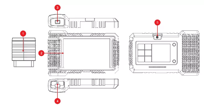
- Bluetooth Diagnostic Dongle: Green: device is powered on. blue: bluetooth is connected. red: there is a fault code.
- Touch Screen: 7 inches (1280*720).
- On/Off key: Long press to switch on/off. click to rest the screen.
- Charging Port: TYPE-C charging port & development system debugging USB port.
- Camera: Support 1300W pixel camera for taking pictures.
2. Connect the KINGBOLEN K7 with your vehicle through the OBDII port
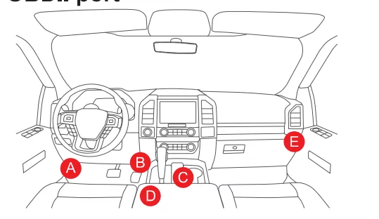
Usually. the OBD port is located under the dashboard. above the pedal on the driver’s side. The five locations shown lite the picture are common OBDII port locations.
3. Turn on the KINGBOLEN K7
After connecting with the car. the screen will display as shown in the picture.
4. Connect Wi-Fi
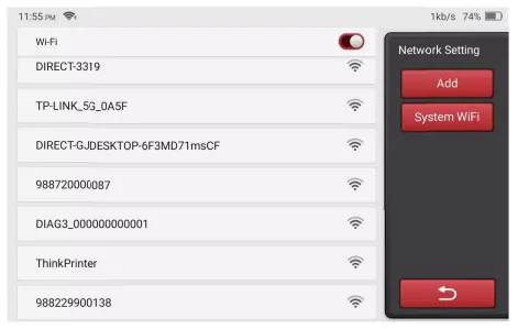
The system will automatically search all available Wi-Fi networks and you can choose the “Wi-Fi” needed. Notice the “Wi-Fi” must be set before use.
5. Activate diagnostic Dongle
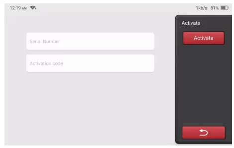
Please enter the SN number and activation code of the connector and click Activate.
Tip: The activation code can be found on the password letter.
6. Functions Description
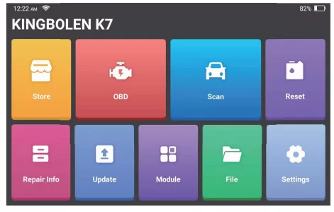
The KINGBOLEN K7 main unit has the following 9 functions:
6.1 Scan
This module has auto search (automatic scanning of car models’ VIN). car model lists. Demo (demonstration of the diagnosis process). History (diagnosis records). OBD&IM (9 emission-related module diagnosis)
6.2 OBD
Support OBD II and EOBD protocols after 1996.
6.3 Module
Support external module. e.g. TPMS
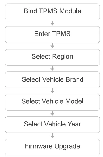
Tip: Please upgrade the firmware in "Settings-Firmware Fix"
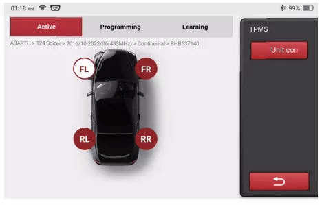
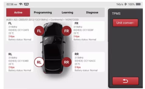
6.3.1 Activate Sensor
This function allows users to activate TPMS sensor to view sensor data such as sensor ID. tire pressure. tire frequency. tire temperature and battery condition. For universal sensors. place the tool by the alongside of the stem. point toward the sensor location. and press the OK button. Once the sensor is successfully activated and decoded. KINGBOLEN K7 will vocally announce that the sensor is activated and the screen will display the sensor data.
I. For early magnet-activated sensors. place the magnet over the stem and then place the TPMS module accessorg by the alongside of the stem.
II. If the TPMS sensor requires tire deflation (about 10PSI). then deflate the tire and place the TPMS modle accessorg by the alongside of the stem while pressing the OK button.
Repeat this step to check other vehicle sensors. After all sensors are successfully activated. the following interface will appear.
6.3.2 Program Sensor
This function allows users to program sensor data to kingbolen sensors to replace faulty sensors that are with low battery capacity or not functioning. The following options are available for programming kingbolen sensors: Automatically Create (Auto). Manually Create (Manual) and Copy ID by Activation (Replication).
Auto: This function is designed to program kingbolen sensors by applying random IDs. created according to the test vehicle when it is unable to obtain the original sensor IDs. Select the wheel which needs to be programmed. place a kingbolen sensor close to the TPMS antenna of the tool. and select “Auto” to create a random sensor ID.
Manual: This function allows users to manually input sensor ID. Users can input a random ID or the original sensor ID if it is available.
Replication: This function allows users to write in the retrieved original sensor data to the kingbolen sensor. It is used after the original sensor is activated.
Programming steps:
a. Place a kingbolen sensor close to the TPMS antenna of the tool
b. Select the wheel (FL. FR. RL. RR) that the sensor is to be installed in
c. Select the programming method (Auto. Manual. Replication)
d. Click “Programming”
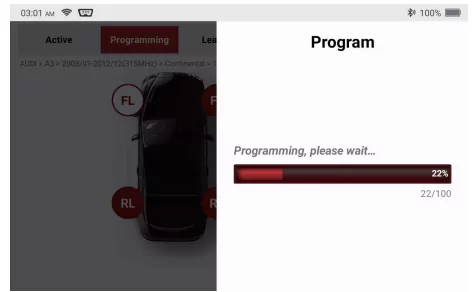
The programming process normally takes in 1 minute. and it would vocally announces the programming result. with sensor data displayed on the screen after it completes.
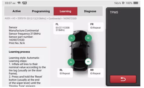
6.3.3 Relearn Sensor
This function allows users to check and view the detailed TPMS sensor relearn procedures. Relearn operation applies only when the newly programmed sensor IDs are different from the original sensor IDs stored in the vehicle’s ECU. Relearn is used to write the newly programmed sensor IDs into the vehicle’s ECU for sensor recognition.
6.4 Reset
Supports the most common multiple maintenance and reset functions. it involves in 28 reset functions. there are shown as follows: Maintenance Light Reset (OIL); Steering Angle Reset (SAS); Battery Matching (BMS); ABS Exhaust (ABS); Throttle Matching (ETS); Brake Pad Reset (EPB); DPF Regeneration (DPF); Anti theft Matching (AFS); Injector Coding (INJEC); Tire Pressure Reset (TPMS); Suspension Level Calibration (SUS); Headlight Matching (AFS); Gearbox Matching(Gearbox); Sunroof Initialization (SUN); EGR Adaption (EGR); Gear Learning (Gear); ODO Reset (ODO); Airbag Reset (Airbag); Transport Mode (Transport); A/F Reset (A/F); Stop/Start Reset (Stop/Start); NOx Sensor Reset (NOx); AdBlue Reset (Diesel Engine Exhaust Gas Filter) (AdBlue); Seat Calibration (SeatS); Coolant Bleeding (Coolant); Tyre Reset (Tyre);
6.5 Store
Display related products. please contact the dealer if necessary.
6.6 Module
It involves 4 functional modules shown as follows.
PRINTER -- Thermal printer for diagnostic reports. (with professional PRINTER thermal printing paper)
Endoscope -- HD video endoscope module.
Battery tester -- battery tester module.
ScopeBox -- oscilloscope module.
Note: Please purchase the 4 functional modules from the Store.
6.7 Repair Info
Coverage lists: Quickly check the models and functions supported by the current device. Learning: Videos contain guidelines for equipment use. maintenance. and diagnostics. Video: The learning course demonstrates how to operate the tool. User Manual: Help technicians quickly grasp the usage of equipment and efficiently improve diagnostic capabilities.
6.8 File
It is used to record and establish the files of the diagnosed vehicles. The files are created based on the vehicle VIN and the check time. including all diagnostic related data such as diagnostic reports. data stream records and screenshots.
6.9 Setting
Common system settings can be made here to modify and add information.
7. Settings
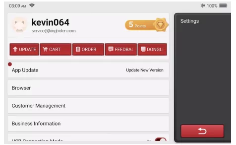
You can do some basic set up in this page. Include Wi-Fi. screen brightness. language. time zone. and so on.
Feedback: You can feedback the diagnostic software/app bugs to us for analysis and improvements.
Update: This module allows you to update the diagnostic software & App and set up frequently used software.
* Screenshots: Turn on this switch to take a screen capture.
* Screen floating window: Turn on this switch to record the screen operation video.
* Network: Set the connectable Wi-Fi network.
Firmware fix: Used to update the firmware.
* Language: Select the tool language.
* Time zone: Choose the time zone of the current location. then the system will automatically configure the time according to the time zone you chose.
8. FAQ
Here we list some common questions and answers related to this tool.
Q: Why does it have no responses when connected to a vehicle?
A: Check whether the connection with the vehicle diagnostic port is proper. whether the ignition switch is on. and whether the tool supports the vehicle.
Q: Why does the system stop while reading the data stream?
A: This may be caused by loose diagnostic connection. Please unplug the connector and reconnect it firmly.
Q: Communication error with vehicle ECU?
A: Please confirm:
1. Whether diagnostic connector is correctly connected.
2. Whether ignition switch is ON.
3. If all checks are normal. please send vehicle year. make. model and VIN number to us by Feedback function.
Q: Why does the screen flash when the engine ignition starts?
A: It is normal and caused by electromagnetic interference.
Q: How to upgrade the system software?
A: 1. Start the tool and ensure a stable Internet connection.
2. Go to "Settings" -> “App Update”. click "OTA" and then click “check version” to enter the system upgrade interface.
3. Complete the process by following the instructions on the screen step by step. It may take a few minutes. After successfully completing the upgrade. the tool will automatically restart and enter the main interface.
9. Warranty Terms
This warranty applies only to users and distributors who purchase KINGBOLEN K7 products through normal procedures. Provide free warranty within one year. KINGBOLEN TECH warrants its electronic products for damages caused by defects in materials or workmanship.
Damages to the equipment or components caused by abusing. unauthorized modification. using for non-designed purposes. operation in a manner not specified in the instructions. etc.are not covered by this warranty. The compensation for dashboard damage caused by the defect of this equipment is limited to repair or replacement. KINGBOLEN TECH does not bear any indirect and incidental losses. KINGBOLEN TECH will judge the nature of the equipment damage according to its prescribed inspection methods. No agents. employees or business representatives of KINGBOLEN TECH are authorized to make any confirmation. notice or promise related to KINGBOLEN TECH products.
Service Line: (+86)0755-23445106
Customer Service Email: [email protected]
Official Website: www.kingbolen.com
Youtube: Kingbolen auto scanner center
Facebook: @kingbolen.fans
Instagram: @kingbolen.fans
Products tutorial. videos. FAQ and coverage list are available on kingbolen official website.