Version: V1.00.001

I
FCC Requirement
Changes or modications not expressly approved by the party responsible for compliance could void the
user’ s authority to operate the equipment.
This device complies with Part 15 of the FCC Rules. Operation is subject to the following two conditions:
(1) this device may not cause harmful interference, and
(2) this device must accept any interference received, including interference that may cause undesired
operation.
Note: This equipment has been tested and found to comply with the limits for a Class B digital device,
pursuant to Part 15 of the FCC Rules. These limits are designed to provide reasonable protection
against harmful interference in a residential installation. This equipment generates, uses, and can
radiate radio frequency energy, and if not installed and used in accordance with the instructions, may
cause harmful interference to radio communications. However, there is no guarantee that interference
will not occur in a particular installation. If this equipment does cause harmful interference to radio
or television reception, which can be determined by turning the equipment o and on, the user is
encouraged to try to correct the interference by one or more of the following measures:
– Reorient or relocate the receiving antenna.
– Increase the separation between the equipment and receiver.
– Connect the equipment into an outlet on a circuit dierent from that to which the receiver is connected.
– Consult the dealer or an experienced radio/TV technician for help.
FCC WARNING
This equipment may generate or use radio frequency energy. Changes or modications to this equipment
may cause harmful interference unless the modications are expressly approved in the instruction manual.
The user could lose the authority to operate this equipment if an unauthorized change or modication is
made.
This device complies with part 15 of the FCC Rules. Operation is subject to the following two conditions: (1)
This device may not cause harmful interference, and (2) this device must accept any interference received,
including interference that may cause undesired operation.
NOTE: This equipment has been tested and found to comply with the limits for a Class B digital device,
pursuant to part 15 of the FCC Rules. These limits are designed to provide reasonable protection against
harmful interference in a residential installation. This equipment generates, uses and can radiate radio
frequency energy and, if not installed and used in accordance with the instructions, may cause harmful
interference to radio communications. However, there is no guarantee that interference will not occur in
a particular installation. If this equipment does cause harmful interference to radio or television reception,
which can be determined by turning the equipment o and on, the user is encouraged to try to correct the
interference by one or more of the following measures:
• Reorient or relocate the receiving antenna.
• Increase the separation between the equipment and receiver.
• Connect the equipment into an outlet on a circuit dierent from that to which the receiver is connected.
• Consult the dealer or an experienced radio/TV technician for help.
• The rating information is located at the bottom of the unit.

II
FCC/IC RF Radiation Exposure and SAR Statements
The device has been tested for body-worn Specic Absorption Rate (SAR) compliance. The FCC/IC
has established detailed SAR requirements and has established that these requirements. RF Exposure
Information The radio module has been evaluated under FCC Bulletin C95.1 and IEEE 1528 and found to
be compliant to RF Exposure from radio frequency devices. This model meets the applicable government
requirements for exposure to radio frequency waves. The highest reported SAR level for usage near the
body (0mm) is 0.63 W/kg.
IC Statements
This device complies with Industry Canada Iicense-exempt RSS standard(s). Operation is subject to the
following two conditions: 1. This device may not cause interference, and 2. This device must accept any
interference, including interference that may cause undesired operation of the device.
Le présentappareilestconforme aux CNR d'Industrie Canada applicables aux appareils radio exempts de
licence. L'exploitationestautorisée aux deux conditions suivantes:
(1) l'appareil ne doit pas produire de brouillage, et (2) l'utilisateur de l'appareildoit accepter tout
brouillageradioélectriquesubi, mêmesi le brouillageest susceptible d'encompromettre le fonctionnement.

III
Copyright Information
Copyright © 2022 by SHENZHEN KINGBOLEN ELECTRONIC TECHNOLOGY.,LTD (hereinafter referred
to as “KINGBOLEN”). All rights reserved. No part of this publication may be reproduced, stored in a
retrieval system, or transmitted in any form or by any means, electronic, mechanical, photocopying and
recording or otherwise, without the prior written permission of KINGBOLEN. The information contained
herein is designed only for the use of this unit. KINGBOLEN is not responsible for any use of this
information as applied to other units.
Neither KINGBOLEN nor its aliates shall be liable to the purchaser of this unit or third parties for
damages, losses, costs, or expenses incurred by purchaser or third parties as a result of: Accident,
misuse, or abuse of this unit, or unauthorized modications, repairs, or alterations to this unit, or failure
to strictly comply with KINGBOLEN operating and maintenance instructions. KINGBOLEN shall not be
liable for any damages or problems arising from the use of any options or any consumable products other
than those designated as Original KINGBOLEN Products or KINGBOLEN Approved Products. Formal
statement: The names of other products mentioned in this manual are intended to explain how to use this
equipment, and the registered trademark ownership still belongs to the original company.
This equipment is designed for professional technicians or maintenance personnel.
Safety Precautions and Warnings
To avoid personal injury, property loss, or accidental damage to the product, read all of the information in
this section before using the product.
Handle equipment carefully
Do not drop, bend, or puncture the tool, or insert extra objects into or place heavy objects on
the device. The vulnerable components inside may be damaged.
Do not disassemble or modify the equipment
The device is a sealed device with no user-serviceable parts inside. All internal repairs must be performed
by an authorized maintenance organization or qualied technician. Attempts to disassemble or modify the
device will void the warranty.
Do not try to replace the internal battery
The internal rechargeable lithium battery must be replaced by an authorized maintenance organization or
qualied technician. Contact the dealer for factory replacement.

IV
Adapter information
Avoid immersing the device in water or placing it in a location where it may absorb moisture or other liquids.
During normal use, the charging device may become hot. Please ensure that there is good ventilation
while charging device.
If any of the following situation occurs, please unplug the charging device:
• The charging device is exposed to rain, liquid or in an environment with excessive overlap.
• The charging device showed physical damage.
• Cleaning the charging device.
Data and Software Protection
Do not delete unknown les or change the names of les or directories created by others, otherwise the
device software may not run.
!
Note: Access to network resources makes the device vulnerable to computer viruses, hackers, spyware, and
other malicious behaviors, and may damage the device, software, or data. To make ensure that you are using
rewalls, anti-virus software and anti-spyware software to provide adequate protection for your computer and
keep these softwares up to date.
Precautions on Using this tool
• To make sure the ignition switch should be in the OFF position when plugging and unplugging the
diagnostic connector.
• Keep the connector in the storage box on the back of the main unit, when the vehicle diagnosis is nished.
• Gently press the diagnostic connector to pop up the diagnostic connector. Do not pull or use sharp
objects to pry the diagnostic connector.
Precautions on Operating Vehicle’s ECU
• Do not disconnect battery or any wiring cables in the vehicle when the ignition switch is on, as this could
avoid damage to the sensors or the ECU.
• Do not place any magnetic objects near the ECU. Disconnect the power supply to the ECU before
performing any welding operations on the vehicle.
• Use extreme caution when performing any operations near the ECU or sensors. Ground yourself when
you disassemble PROM, otherwise ECU and sensors can be damaged by static electricity.
• When reconnecting the ECU harness connector, be sure it is attached firmly, otherwise electronic
elements, such as ICs inside the ECU, can be damaged.

V
Content
1. Quick Start Manual ............................................................................................................ 1
1.1 Initial Use ............................................................................................................................................. 1
1.1.1 Turn on the Machine .................................................................................................................. 1
1.1.2 Language Setting ........................................................................................................................ 1
1.1.3 Connect Wi-Fi ............................................................................................................................. 1
1.1.4 Choose Time Zone ..................................................................................................................... 2
1.1.5 User Agreement .......................................................................................................................... 2
1.1.6 Create an Account ...................................................................................................................... 2
1.1.7 VCI Activation ............................................................................................................................. 3
1.2 Diagnosis Flowchart ............................................................................................................................ 3
1.3 Function Menu ..................................................................................................................................... 4
1.4 Charging .............................................................................................................................................. 5
1.5 Battery ................................................................................................................................................. 5
1.6 VCI Connections.................................................................................................................................. 5
1.7 Scope Box / Video Scope / Printer Installation .................................................................................... 8
1.8 Wireless TPMS / Battery Tester Installation (Bluetooth). ..................................................................... 9
2. Introduction ........................................................................................................................9
2.1 Product Prole (KINGBOLEN K10/K10 Plus) ..................................................................................... 9
2.2 Components & Controls .................................................................................................................... 10
2.3 Parameters ........................................................................................................................................ 12
3. Begin to Use.....................................................................................................................12
3.1 Intelligent Diagnosis .......................................................................................................................... 12
3.2 Diagnosis ........................................................................................................................................... 13
3.2.1 Manual Diagnosis ..................................................................................................................... 13
3.2.2 Smart Scan ............................................................................................................................... 14
3.2.3 System Scan ............................................................................................................................. 15
3.2.4 Choose to Scan ........................................................................................................................ 15
3.2.5 System and Function ................................................................................................................ 16
3.3 Quick Check ...................................................................................................................................... 20
3.4 Maintenance ...................................................................................................................................... 21
3.4.1 Oil Reset ................................................................................................................................... 21
3.4.2 Elec. Throttle Adaption .............................................................................................................. 21
3.4.3 Steering Angle Reset ................................................................................................................ 22
3.4.4 Battery Matching ....................................................................................................................... 22
3.4.5 ABS Bleeding ............................................................................................................................ 22
3.4.6 Brake-pad Reset ....................................................................................................................... 22
3.4.7 DPF Regeneration .................................................................................................................... 23
3.4.8 Gear Learning ........................................................................................................................... 23
3.4.9 IMMO Service ........................................................................................................................... 23
3.4.10 Injector Coding ........................................................................................................................ 23
3.4.11 TPMS Reset ............................................................................................................................ 23
3.4.12 Suspension Matching ............................................................................................................. 24
3.4.13 AFS Reset ............................................................................................................................... 24
3.4.14 A/T Learning ........................................................................................................................... 24
3.4.15 Sunroof Initialization ............................................................................................................... 24
3.4.16 EGR Adaption ......................................................................................................................... 24
3.4.17 ODO Reset ............................................................................................................................. 24
3.4.18 Airbag Reset ........................................................................................................................... 24
3.4.19 Transport Mode ....................................................................................................................... 24
3.4.20 A/F Reset ................................................................................................................................ 25
3.4.21 Stop/Start Reset ..................................................................................................................... 25
3.4.22 NOx Sensor Reset .................................................................................................................. 25
3.4.23 AdBlue Reset (Diesel Engine Exhaust Gas Filter) .................................................................. 25

VI
3.4.24 Seat Calibration ...................................................................................................................... 25
3.4.25 Coolant Bleeding .................................................................................................................... 25
3.4.26 Tyre Reset .............................................................................................................................. 25
3.4.27 Windows Calibration ............................................................................................................... 25
3.4.28 Language Change .................................................................................................................. 25
3.4.29 AC System Relearn/Initialization ............................................................................................ 25
3.4.30 Intelligent Cruise Control System .......................................................................................... 25
3.4.31 Engine Power Balance Monitoring ......................................................................................... 26
3.4.32 Gas Particulate Filter Regeneration ....................................................................................... 26
3.4.33 Motor Angle Calibration ......................................................................................................... 26
3.4.34 High Voltage Battery Diagnostics .......................................................................................... 26
3.4.35 IMMO PROG (optional) ......................................................................................................... 26
3.5 TPMS Diagnosis ................................................................................................................................ 26
3.6 ADAS ................................................................................................................................................. 27
3
.
7
Module ............................................................................................................................................... 28
3.8 Remote Assistance ............................................................................................................................ 28
3.9 Store .................................................................................................................................................. 29
3.10 File ................................................................................................................................................... 29
3.11 Repair Info ....................................................................................................................................... 30
3.11.1 OBD Fault Code Library .......................................................................................................... 30
3.11.2 Coverage List .......................................................................................................................... 30
3.11.3 Learning materials .................................................................................................................. 30
3.11.4 User Manual ............................................................................................................................ 30
3.12 Update ............................................................................................................................................. 30
3.13 Feedback ......................................................................................................................................... 31
4. User Info ...........................................................................................................................32
4.1 VCI..................................................................................................................................................... 33
4.2 Activate VCI ....................................................................................................................................... 33
4.3 Activate TPMS VCI ............................................................................................................................ 33
4.4 Fix VCI rmware/system .................................................................................................................... 34
4.5 Data Stream Sample ......................................................................................................................... 34
4.6 My Order............................................................................................................................................ 34
4.7 Prole ................................................................................................................................................ 34
4.8 Change Password ............................................................................................................................ 34
4.9 Wi-Fi ................................................................................................................................................. 34
4.10 Diagnostic Software Clear ............................................................................................................... 34
4.11 Business Information ....................................................................................................................... 34
4.12 Customer Management ................................................................................................................... 34
4.13 Diagnostic Record ........................................................................................................................... 35
4.14 Photo Album .................................................................................................................................... 35
4.15 Screen Recorder ............................................................................................................................. 35
4.16 Clear VCI Data ................................................................................................................................ 35
4.17 Settings............................................................................................................................................ 35
4.17.1 Check for Updates .................................................................................................................. 35
4.17.2 Sleep Time .............................................................................................................................. 35
4.17.3 Privacy Policy ......................................................................................................................... 35
4.17.4 System Upgrade ..................................................................................................................... 35
4.17.5 Units ........................................................................................................................................ 36
4.17.6 Clear Cache ............................................................................................................................ 36
4.17.7 Mode Switch ........................................................................................................................... 36
4.17.8 Restore Factory Settings ........................................................................................................ 36
4.18 Hotkey Setting ................................................................................................................................. 36
5.FAQ ....................................................................................................................................37
1
1. Quick Start Manual
1.1 Initial Use
The following settings should be made when you initially use the device.
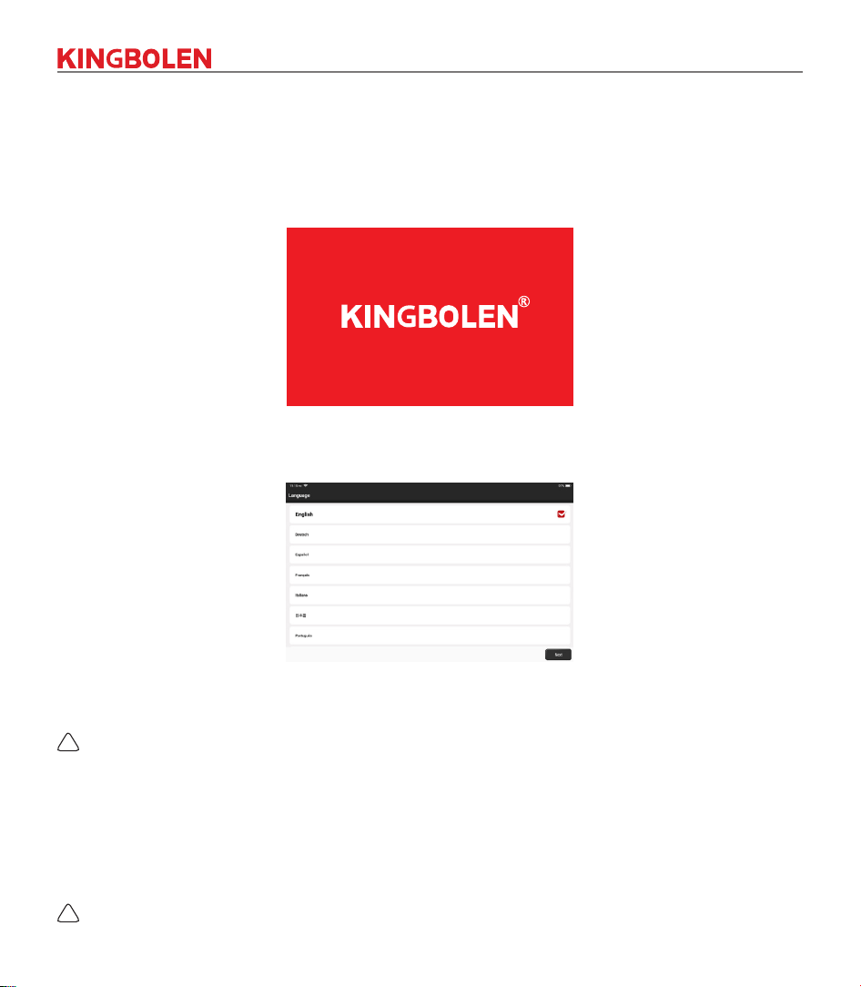
1.1.1 Turn on the Machine
After pressing the power button, images will be shown on the screen as follows.
1.1.2 Language Setting
Select the target language from the languages displayed on the interface.
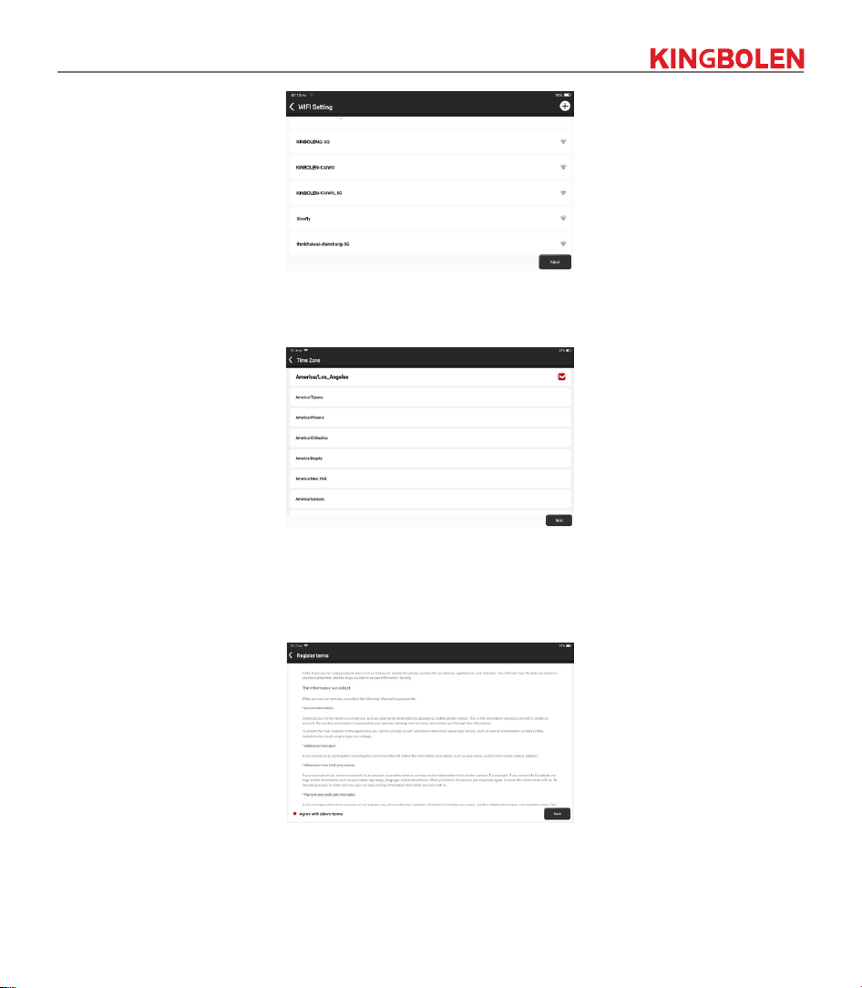
1.1.3 Connect Wi-Fi
The system will automatically search all available Wi-Fi networks. Please connect to the trusted Wi-Fi.
!
Tips: Wi-Fi must be set. If there is no Wi-Fi network is available nearby, you can try "Portable Mobile
Hotspot".
!
2
1.1.4 Choose Time Zone
Choose the time zone of the current location, then the system will automatically cogure the time.
1.1.5 User Agreement
Please read all the terms and conditions of the user agreement carefully. Choose “Agree all the above
terms”, and tap “Next” to complete the registration process.
Then the page will jump to the “Congratulations on your successful registration” interface.
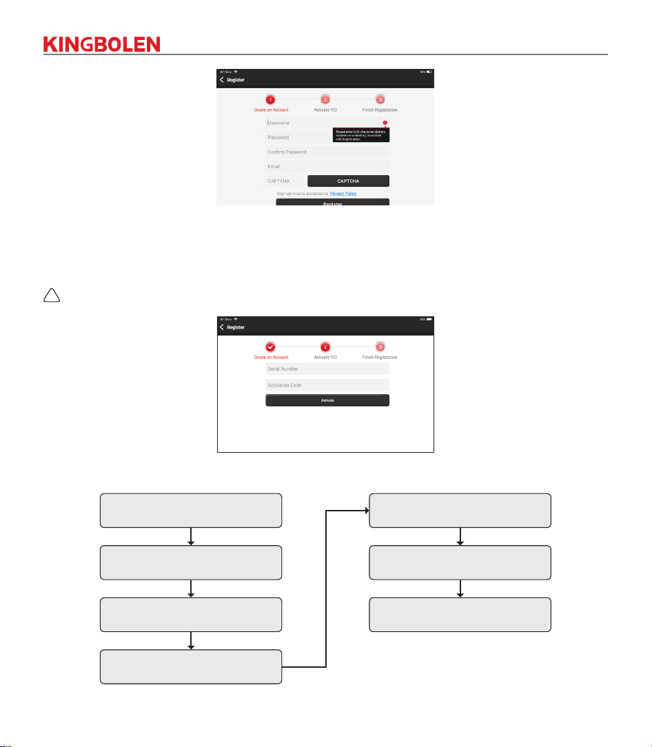
1.1.6 Create an Account
You need to use your email account to register a KINGBOLEN personal account. This account can
be applied to all KINGBOLEN products, and you can log in directly with this account when using other
KINGBOLEN device.
3
1.1.7 VCI Activation
Enter the connector serial number and activation code to activate and bind the diagnostic connector. If
you have not activated it, you can also tap "Settings" on the main interface to enter and select "Activate" to
operate.
!
Tips: The activation code is an 8-digit number and is pasted on the "password letter".
1.2 Diagnosis Flowchart
Register / Create an Account
Connect Diagnostic Connector
BT Connection
Activation
Log in Choose Vehicle Type
Choose System
4
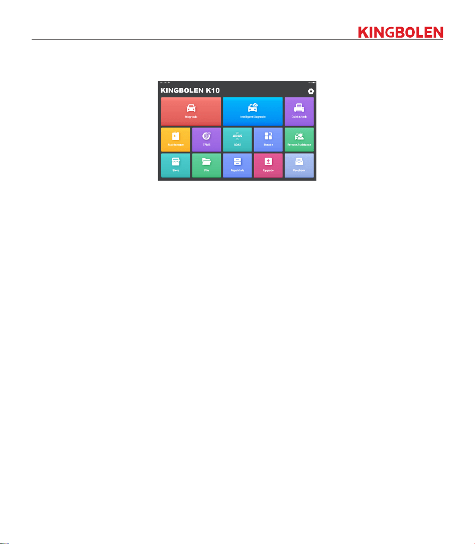
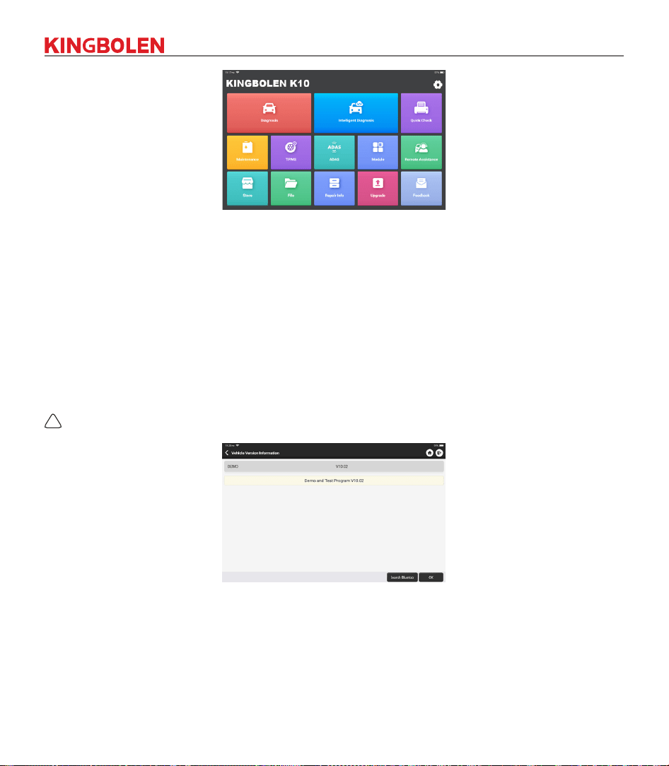
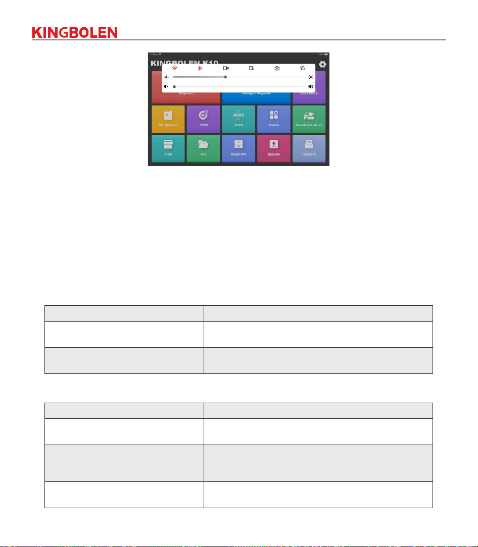
1.3 Function Menu
After startup, the system will automatically enter the homepage:
It mainly includes the following features:
• The device and diagnostic connector support wired communication and Bluetooth communication.
• Support powerful intelligent VIN recognition technology, which is convenient, fast and ecient.
• Quick check: Automatic Identication of Vehicle Information, Auto Checking and Report Printing.
• Modular expansion: printer, video scope, scope box, battery test clip, wireless TPMS tool.
• It can detect faults in the electronic control systems of most high-end, medium-end, and low-end vehicles
in Asia, Europe, the United States and China. Powerful diagnostic functions include reading fault codes,
clearing fault codes, reading data streams, action tests, and other special functions.
• Maintenance function: matching, coding, programming of most vehicles’ programmable modules,
and most commonly used maintenance and reset functions: Oil Reset; Elec. Throttle Adaption; IMMO
Service; Injector Coding; Brake-pad Reset; Steering Angle Reset; ABS Bleeding; AFS Reset; Battery
Matching; A/T Learning; DPF Regeneration; EGR Adaption; TPMS Reset; Sunroof Initialization;
Suspension Matching; Gear Learning; Airbag Reset; ODO Meter Reset; AdBlue Reset; A/F Reset;
Coolant Bleeding; Language Change; NOx Sensor Reset; Seat Calibration; Stop/Start Reset; Transport
Mode; Tyre Reset; Windows Calibration; AC System Relearn/Initialization; Engine Power Balance
Monitoring; Gas Particulate Filter Regeneration; High Voltage Battery Diagnostics; Intelligent Cruise
Control System; Motor Angle Calibration; IMMO PROG (optional).
• TPMS: with wireless TPMS tool (optional), TPMS activation, programming and learning functions can be
supported.
• Diagnostic software, client-side and rmware can be updated online.
• Feedback: In the process of diagnosis, if the software or function is abnormal, please feed back to us.
Our professionals will follow up and deal with it in time.
5
1.4 Charging
Follow the steps below to charge the device:
• Use the charger to connect the device and the power socket to charge.
• When the battery status displays , the device is charging.
When it displays , the charging process has been completed and you shall disconnect the device.
1.5 Battery
• It is normal that the device cannot be turn on when charging because the battery has not been used for
a long time or maybe the power is exhausted. Please turn on the device again after charging the battery
for a while.
• Please use the charger in the package to charge the device. Except for the chargers specied by the
company, the company shall not be liable for any damage and loss caused by charging with other
chargers.
• The battery can be recharged repeatedly. Please try not to recharge frequently to avoid battery loss and
prolong battery life.
• The battery charging time varies with temperature and battery status.
• When the battery power is low, the system will pop up a prompt to remind you to connect the charger.
When the battery power is too low, the device will turn o.
1.6 VCI Connections
Connection steps as below:
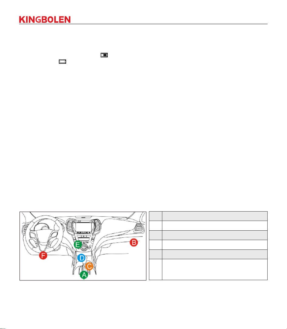
(1) Locate vehicle’s DLC socket. Most of the DLC are standard OBDII/EOBD diagnostic sockets (non-
standard OBDII/EOBD vehicle diagnostic sockets need to use the corresponding adapter). The DLC
is usually located 12 inches from the center of the instrument panel (dash), under or around the
driver’s side for most vehicles. If the DLC cannot be found, refer to the vehicle’s service manual for the
location.
A Opel, Volkswagen, Audi
B Honda
C Volkswagen
D Opel, Volkswagen, Citroen
E Changan
F
Hyundai, Daewoo, Kia, Honda, Toyota, Nissan,Mitsubishi,
Renault, Opel, BMW, Mercedes-Benz, Mazda, Volkswagen,
Audi, GM, Chrysler,Peugeot, Regal, Beijing Jeep, Citroen and
most prevailing models
(2) For OBDII/EOBD vehicle, follow the steps below to proceed:
a. Plug the VCI dongle into the vehicle’s DLC socket
b. Use the OBDII/EOBD extension cable to connect the VCI dongle and DLC socket.
6
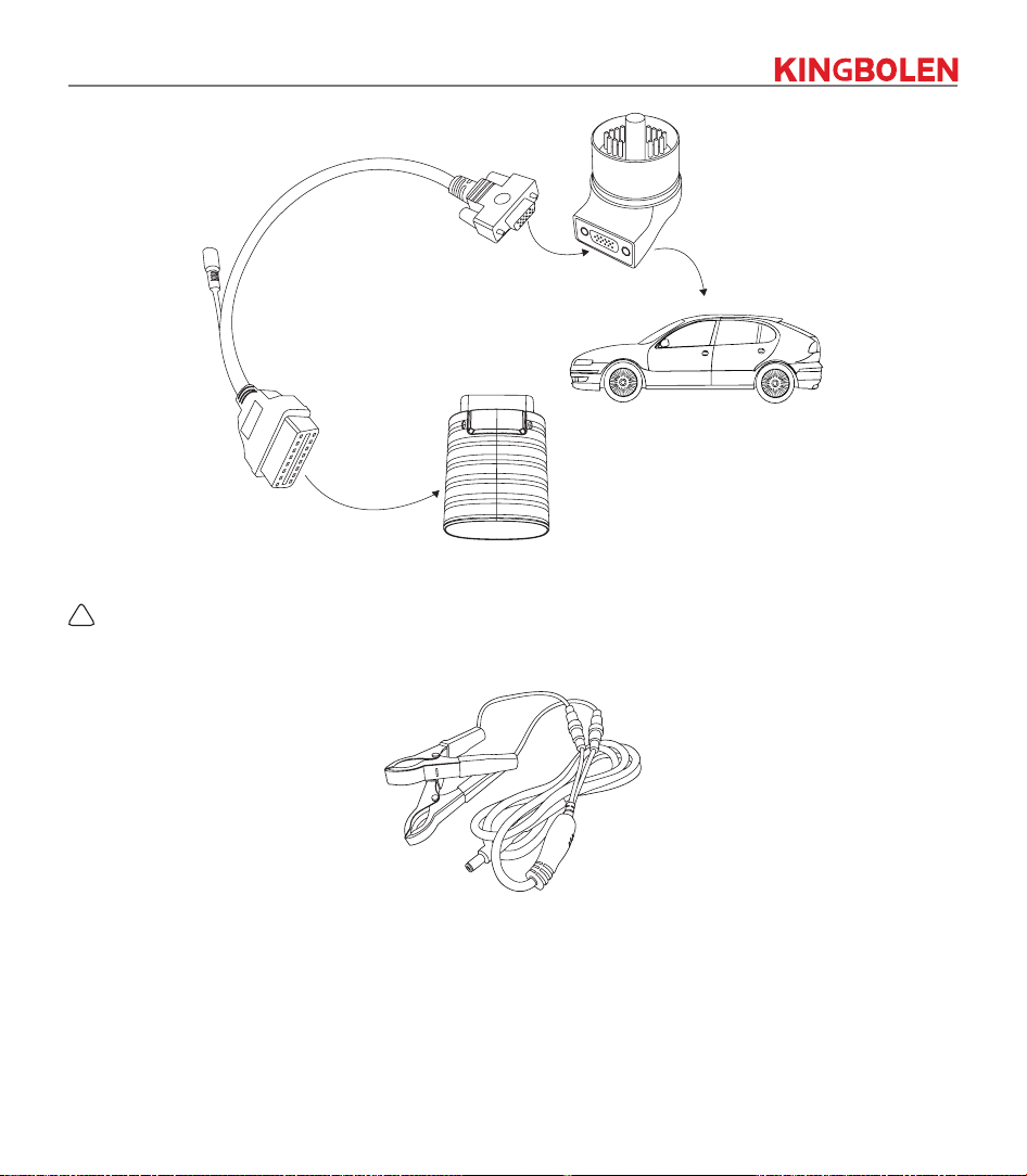
(3) For non-OBDII/EOBD vehicle, If the pin of the DLC is damaged or has insucient power, please try any
of the following methods to proceed:
a. Cigarette Lighter Cable
b. Battery Clamps Cable
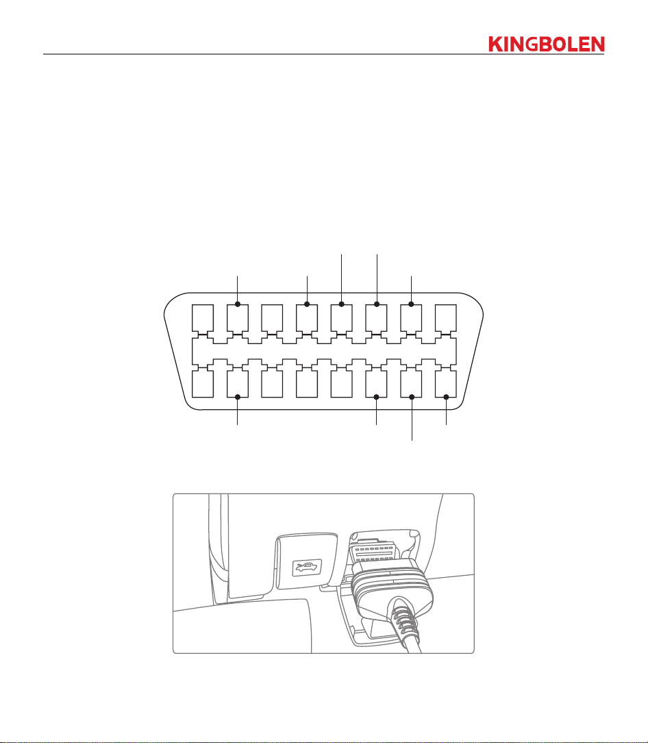
(4) Non-standard 16-PIN vehicle diagnostic sockets (OBDI).
A. Introduction of OBD vehicle diagnosis connector
In the development history of automobile diagnosis and detection, OBD system is an online diagnostic
system for internal combustion engines, which currently goes through a generation and a second
generation, the second generation being EOBD/OBDII, as shown in the diagram below, with a unified
hardware feature and interface denition for the diagnostic seat of the car.
Bus positive line Chassis ground
Signal ground CAN-H line
K-Line
L-Line
CAN-L lineBus negative line Battery power
1 2 3 4 5 6 7 8
9 10 11 12 13 14 15 16
OBD II Connector and Pinout
OBD II Diagnostic Port of Automobile
7
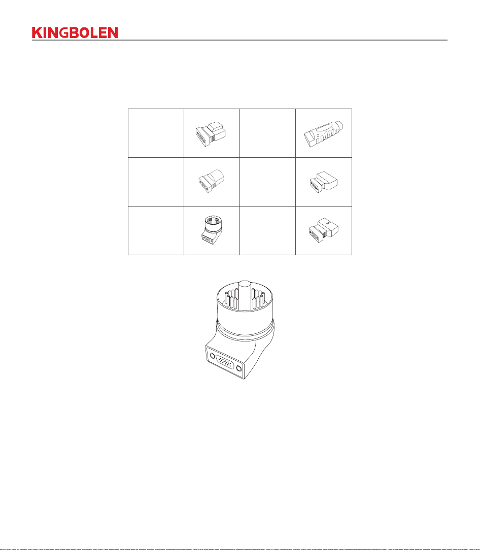
About 1996, before the United States unied the OBD II standard and during the transition period, dierent
automobile manufacturers had dierent diagnostic port for OBD I. Such as three PIN like HONDA; 17 PIN
like Toyota; 38 PIN like BENZ. At present, all overseas comprehensive diagnostic device are equipped with
10 OBD I diagnostic connectors, as shown in the table below:
1 PC
1 PC1 PC
1 PC
BZ-38
TA-22TA-17
CR-6
1 PC
G/V-12
1 PC
B-20
OBD I Diagnostic Port on the Packing List
Diagnostic Connector for BMW 20
B. How to connect OBD I Diagnostic Port
The OBD I connector, which was set up to cater for older models of various car brands, has very few
current applications as most older cars have been phased out. Cars that produced after 2005 are basically
all OBD II connector. In USA, we still occasionally come across vintage or modied cars that still use OBD I.
For this reason, a transfer from OBD II to OBD I is required.
8
OBD I Connector
OBD I Transfer Cable
OBD Connector
Transfer process
Note: when using older models, the Transfer Cable must be used, with the small power connector on it, which is
connected to the power connector of the power double clamp cable, this is a solution for certain cars before 1996,
whose diagnostic holders do not have a 12V power supply.
Application of the double clamp power cable
All other congurations with Non 16-PIN diagnostic connectors can be wired as shown in Picture 5 for
achieving the diagnosis of the corresponding old models.
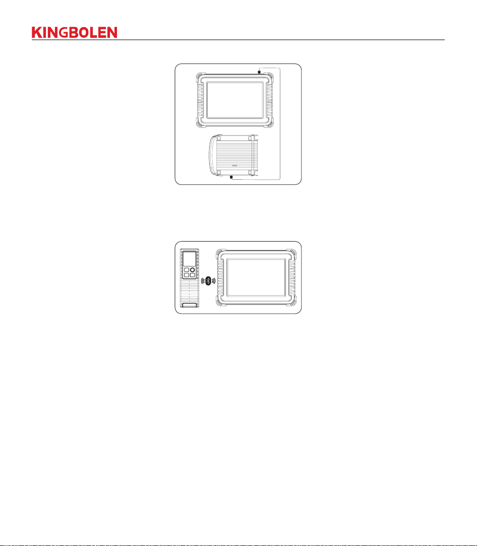
1.7 Scope Box / Video Scope / Printer Installation
The Scope Box and Video Scope are connected by USB cable. It will automatically enter the
corresponding interface once they are connected.
!
9
1.8 Wireless TPMS / Battery Tester Installation (Bluetooth).
Tap Wireless TPMS or Battery Tester, and you can detect the corresponding module in Bluetooth mode.
You need to match the module by activating it.
2. Introduction
2.1 Product Prole (KINGBOLEN K10/K10 Plus)
The device based on the Android 10 System, is a new generation of modular high-end intelligent
diagnostic equipment developed by KINGBOLEN. The device adopts a unique modular design to meet
various application scenarios, including diagnostic module, printer, videoscope, work light, thermal imager,
scope box, moduledock and TPMS tool.
10
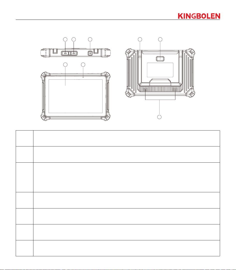
2.2 Components & Controls
1 7
4 3 2 58
6
No. Function
1 Display
2
Power Key
:
Hold the button for 3 seconds to turn the device on, or o, and 10 seconds for a forced restart.
Press the button to wake up the device or turn o the device.
3 Type C Port: connect the supplied charger for charging.
4 USB Port: Reserved for add-on modules and other devices with similar port.
5 8 Megapixel Rear Camera
6 Speaker
11
7 8 Megapixel Front Camera
8
Adjustable Kickstand: Able to keep the device standing on the desk, or hang the device on the
steering whel with 180 degree rotation.
2
1
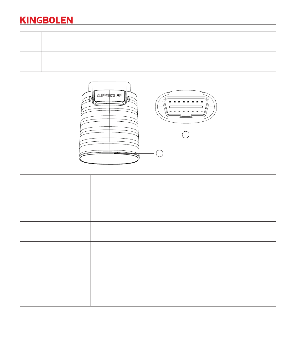
NO. Name Descriptions
1 Indicator Light
LED indicator is located at the bottom, and the three status as follows:
• Power: Green light indicates that the power is on.
• Diagnosis: Blue light shows that it enter the diagnosis mode.
• Vehicle: Flashing-blue light means it is communicating with the vehicle.
2 Diagnostic Port
Plug in the diagnostic cable whose OBD 16-pin connector is linked to
the DLC of the vehicle.
3
Supporting
protocols
ISO 9142 Middlespeed CAN
ISO 14230 Lowspeed and Singlewire CAN
ISO 15765 GM UART
K/L-Line TP 2.0
Flashing Code TP 1.6
CAN ISO 11898 UART Echo Byte Protocol
SAE-J1850 VPW Honda Diag-H Protocol
SAE-J1850 PWM Fault-Tolerant CAN
Highspeed CAN SAE-J2610

12
2.3 Parameters
K10 K10 PLUS
Operating System Android 10.0 Android 10.0
Memory 4G 4G
Storage 64G 128G
Battery 12600mAh\3.7V 12600mAh\3.7V
Screen 10 inches 10 inches
Camera
Front Camera 8.0MP
Rear Camera 8.0MP
Front Camera 8.0MP
Rear Camera 8.0MP
Network Wi-Fi, WLAN 802.11b/g/n Wi-Fi, WLAN 802.11b/g/n
Bluetooth Bluetooth 5.1 Bluetooth 5.1
Working Temperature 32
℉
~122
℉(
0
℃
~ 50
℃)
32
℉
~122
℉(
0
℃
~ 50
℃)
Storage Temperature -4
℉
~140
℉
(-20
℃
~ 60
℃)
-4
℉
~140
℉
(-20
℃
~ 60
℃)
3. Begin to Use
Diagnostic function, covering more than 100 car brands, support intelligent diagnosis and traditional
diagnosis, including OBDII full-function diagnosis. Full-system diagnosis includes: read fault code, clear
fault code, read real-time data stream, special function, actuation test. A diagnosis report can be generated
after the diagnosis.
3.1 Intelligent Diagnosis
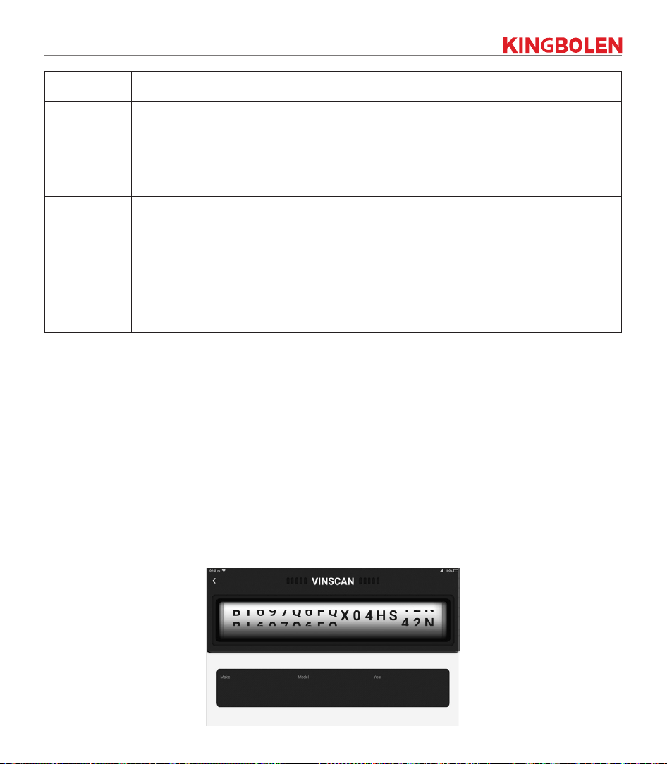
Connect the vehicle first, tap “Intelligent Diagnosis” on the homepage, the device will start the smart
diagnosis program and automatically read the vehicle VIN, as shown in below:
13
If the device failed to access the VIN information, please use “Diagnosis”. At this point, you need to
manually input the VIN code to gain the car information.
3.2 Diagnosis
In this mode, user can manually select vehicle models and systems for diagnosis.
3.2.1 Manual Diagnosis
The device also supports step-by-step manual selection of menus for diagnosis.
To use the "DEMO" as an example to introduce how to start the diagnosis as below.
1. Select vehicle type: on the "demo" on the main diagnostic interface to enter.
!
Tips: The diagnosis menu varies with dierent vehicles
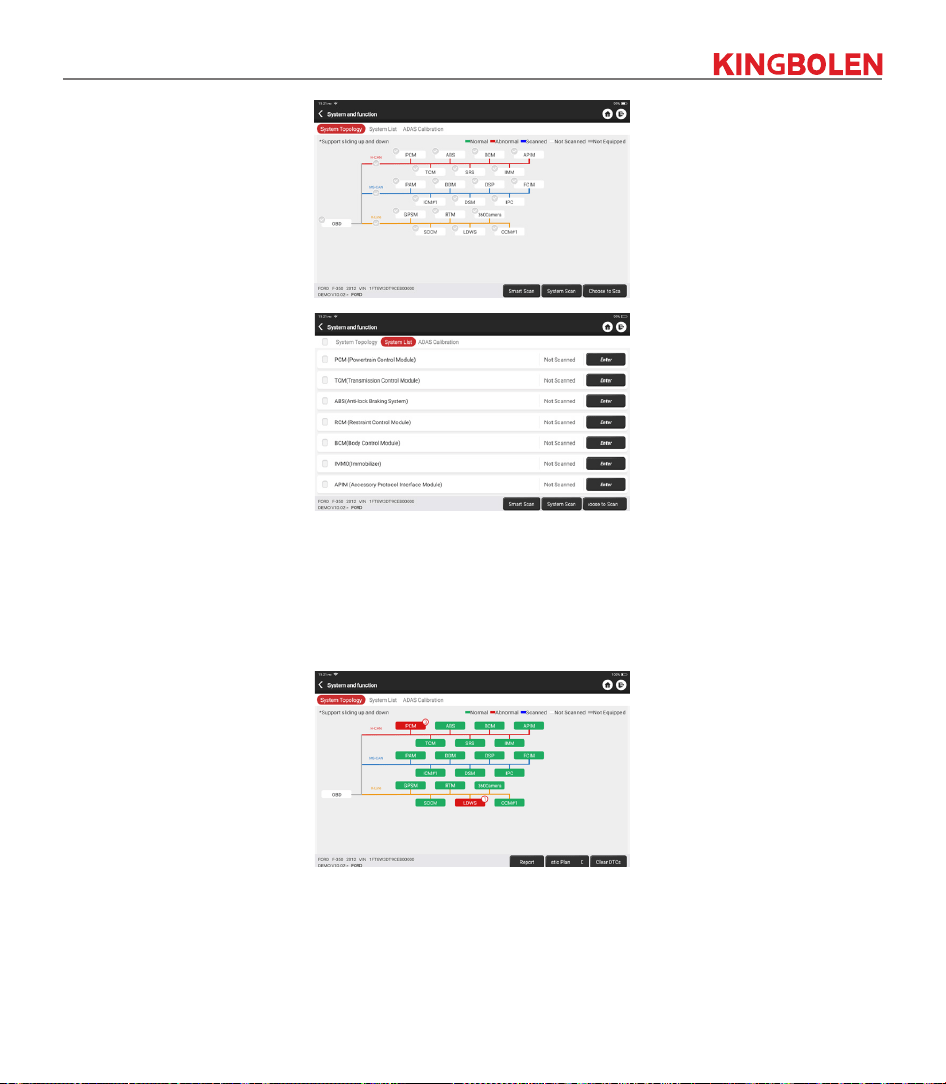
2. Select Diagnostic method: The interface has two display modes of system topology and system list, with
the same functions. Switch according to personal preference.
14
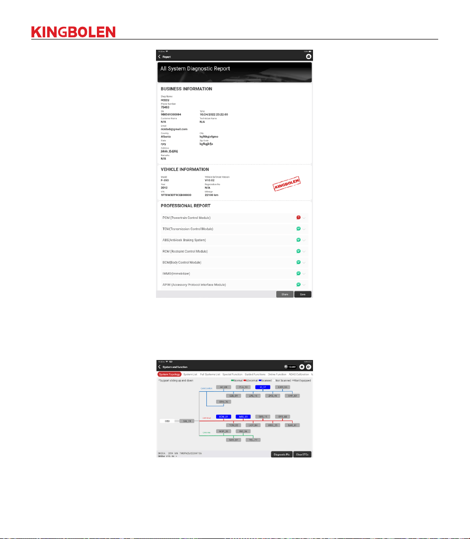
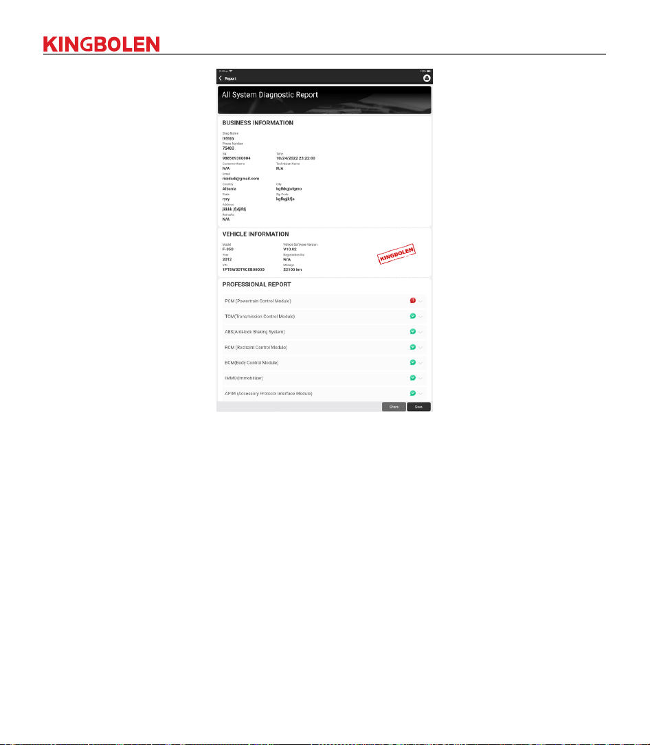
3.2.2 Smart Scan
It enables you to quickly access all the electronic control units of the vehicle and generate a detailed report
about vehicle health. (This function varies from vehicle to vehicle.)The system will start scanning Electronic
Control Units to see if there are fault code and displays the specic results.
Tap "Report" to generate a vehicle health report.
15
3.2.3 System Scan
To check how many systems the car is equipped with.
3.2.4 Choose to Scan
Choose the target automotive electronic control system to scan.
16
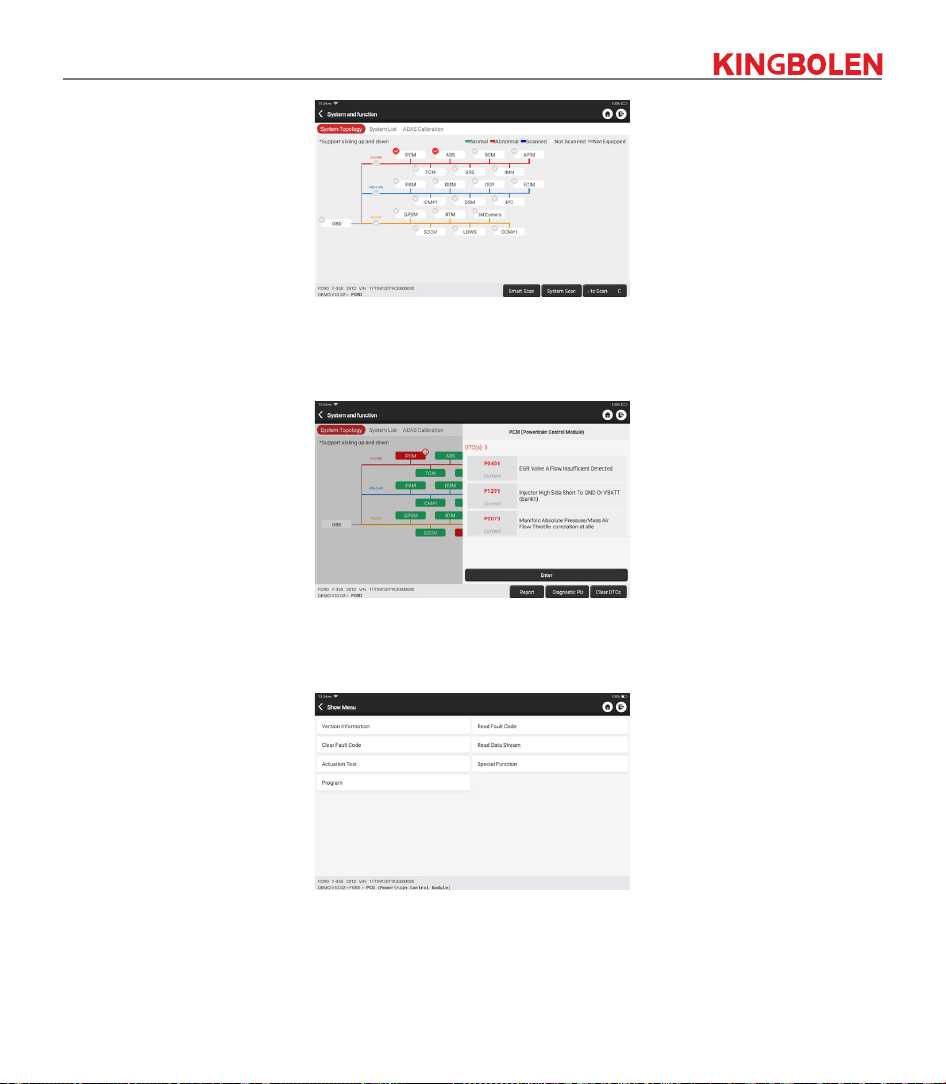
3.2.5 System and Function
After “Smart Scan”, And then we can choose one system to check the detail information. Tap “PCM” as an
example to demonstrate. The following page shows the selection interface.
To check “System and Function”, tap “Enter” to get a corn interface, which is the functional interface of
each electronic control unit.
A
.
Version Information
As shown in the picture, “Version Information” to read the current version information of the car ECU.
B. Read Fault Code
This function is to read the DTC in the ECU memory, helping maintenance personnel to quickly identify
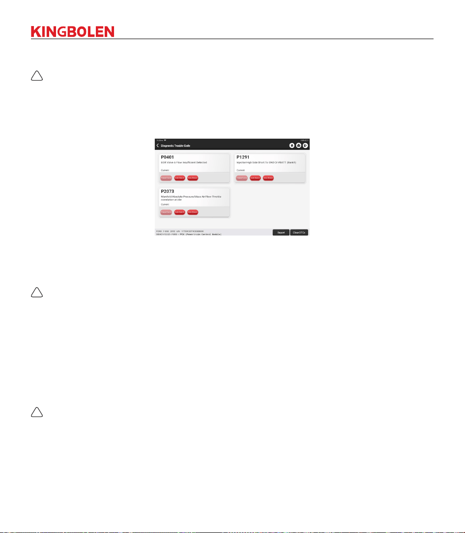
17
the cause of the vehicle breakdown.As shown below, “Read Fault Code”, and then the screen will display
diagnostic results.
!
Tips: Reading the DTC when troubleshooting a vehicle is only a small step in the entire diagnostic process.
Vehicle DTC are for reference only, and parts cannot be replace directly based on the given DTC denition.
Each DTC has a set of test procedures. The maintenance technician must strictly conform to the operation
instructions and procedures described in the car maintenance manual to confirm the root cause of the
breakdown.
C. Clear Fault Code
On the diagnostic function selection screen, tap Clear Fault Code, the system will automatically delete the
currently existing DTCs and display the dialog box of "DTCs Cleared".
!
Note: For general models, please operate strictly according to the normal sequence: read DTC - clear DTC -
test the car - retrieve DTC for verication - repair the car - clear DTC – recheck the car, to conrm that the
DTC no longer appears.
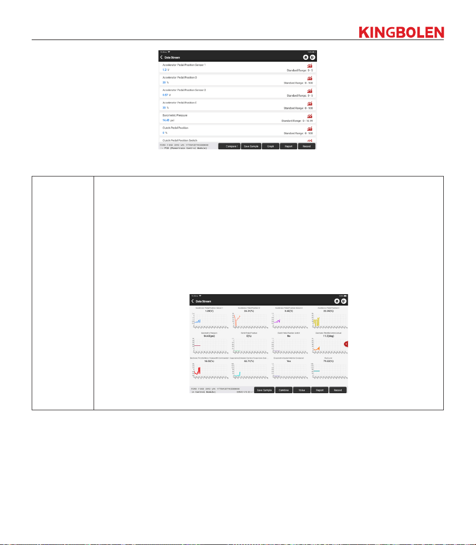
D. Read Data Stream
This option lets you view and capture (record) real-time Live Data of ECU. This data, including current
operating status for parameters and/or sensor information, can provide insight on overall vehicle
performance. It can also be used to guide vehicle maintenance.
Select all and tap "ok" or just select the one you would like to check.
!
Note: If you must drive the vehicle in order to perform a troubleshooting procedure, ALWAYS have a second
person
to
help you. Trying to drive and operate the diagnostic device at the same time is dangerous, and could
cause a serious trac accident.
18
On-screen Buttons:
[Graph]
Display the parameters of the selected data stream in waveform. On the data stream
waveform page, you can do the following:
[Combine]: Display in graph merge status for data comparison.
[Value]: Display the parameters in values and shown in list format.
[Customize]: Customize the data stream option to be viewed. Tap the button, a pull-
down list of the data stream items appears on the screen. Select the desired items (max
12 items), and then screen will display the waveforms corresponding to these items
immediately. If you need to remove any items, just deselect them.
19
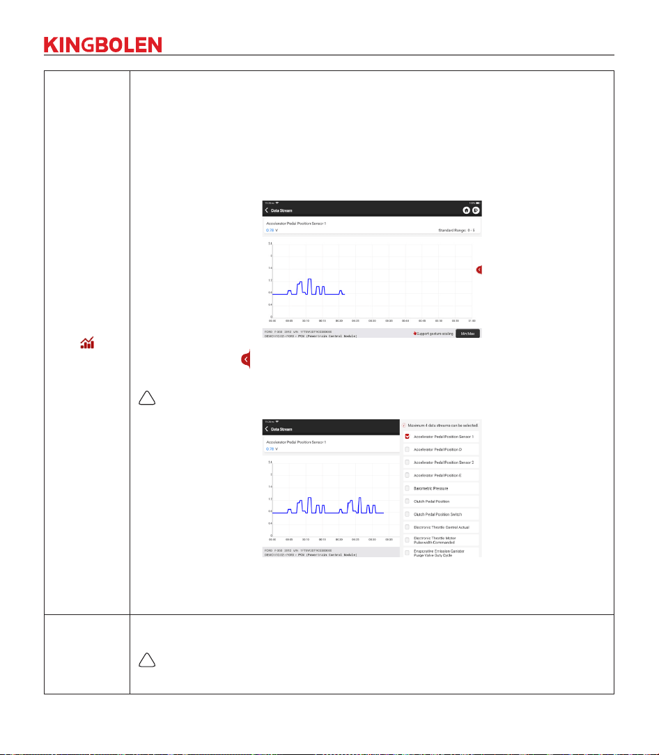
[ ]
Display the current (single) data stream in waveform graph. On the waveform graph
page, you can do the following:
[Min/Max]: To dene the maximum/minimum value. Once the value goes beyond the
specied value, the system will alarm.
[Customize]: Tap “ ” on the right side of the screen, to dene the data stream option
to be viewed.
!
Note: Max 4 data streams can be displayed at the same time.
[Compare
Sample]
To select the sample DS le. All the values you customized and saved in process of DS
sampling will be imported into the Standard Range column for your comparison.
!
Note: Before executing this function, you have to sample the values of data stream items
and save it as a sample Data Stream le.
20
[Report]
To save the value of current data stream.
[Record]
To record diagnostic data, for you to replay and review. Tap “Stop” button to end
reading.
The saved le follows the naming rule: It begins with vehicle type, and then the product
S/N and ends with record starting time. All diagnostic records can be replayed from
User Info -> My Report.
[Save
Sample]
To sample data stream. After sampling, recording and saving the data stream, each
time you review the data stream items, you will be able to call out the corresponding
sample data to overwrite the current standard range.
Tap it to start recording the sample data stream (Note: Only data stream items with
measurement units will be recorded). Once the recording process is complete, tap to
end recording, the system will automatically jump to the data revision screen.
Tap the Min./Max. value to change it. After modifying all desired items, tap Save to
save it as a sample DS le. All DS les are stored in User Info -> Data Stream Sample.
E. Actuation Test
This function is used to test whether the execution components in the electronic control system can work
normally.
F. Special Function
This function is used for data writing operation of electronic control unit. They all belong to this category,
such as ECU data calibration, ECU Programming etc. Some Resetting functions are also included in this
part.
3.3 Quick Check
It adopts smart detection mode. After the vehicle is connected, the system will automatically recognize
the vehicle information, automatically check the vehicle, and automatically generates a report. Automatic
printing can be set so that no human intervention is needed throughout the process.
21
3.4 Maintenance
The device supports matching, coding, programming of most vehicles’ programmable modules, and most
commonly used maintenance and reset functions: Oil Reset; Elec. Throttle Adaption; IMMO Service;
Injector Coding; Brake-pad Reset; Steering Angle Reset; ABS Bleeding; AFS Reset; Battery Matching;
A/T Learning; DPF Regeneration; EGR Adaption; TPMS Reset; Sunroof Initialization; Suspension
Matching; Gear Learning; Airbag Reset; ODO Meter Reset; AdBlue Reset; A/F Reset; Coolant Bleeding;
Language Change; NOx Sensor Reset; Seat Calibration; Stop/Start Reset; Transport Mode; Tyre Reset;
Windows Calibration; AC System Relearn/Initialization; Engine Power Balance Monitoring; Gas Particulate
Filter Regeneration; High Voltage Battery Diagnostics; Intelligent Cruise Control System; Motor Angle
Calibration; IMMO PROG (optional).
3.4.1 Oil Reset
The lightening of the car maintenance light indicates that the vehicle needs maintenance. Reset the
mileage or driving time to zero after the maintenance, so the maintenance light will go out and the system
will start a new maintenance cycle.
3.4.2 Elec. Throttle Adaption
Elec. Throttle Adaption is to utilize the car decoder to initialize the throttle actuator so that the learning

22
value of the ECU returns to the initial state. By doing these, the movement of the throttle (or idle motor)
can be more accurately controlled, thus adjust the intake volume. Situations when throttle matching is
needed:
a. After replacing the electronic control unit, the relevant characteristics of the throttle operation have not
been stored in the electronic control unit.
b. After the electric control unit is powered o, the memory of the electric control unit’s memory is lost.
c. After replacing the throttle assembly, you need to match the throttle.
d. After replacing or disassembling the intake port, the controlling of the idle speed by the coordination
between the electronic control unit and the throttle body is aected.
e. Although the characteristics of the idle throttle potentiometer have not changed, the intake volume has
changed and the idle control characteristics have changed at the same throttle openings.
3.4.3 Steering Angle Reset
To reset the steering angle, rst nd the relative zero-point position for the car to drive in straight line.
Taking this position as reference, the ECU can calculate the accurate angle for left and right steering.
After replacing the steering angle position sensor, replacing steering mechanical parts (such as steering
gearbox, steering column, end tie rod, steering knuckle), performing four-wheel alignment, or recovering
car body, you must reset the steering angle.
3.4.4 Battery Matching
This function enables you to perform a resetting operation on the monitoring unit of vehicle battery, in
which the original low battery fault information will be cleared and battery matching will be done.
Battery matching must be performed in the following cases:
a. Main battery is replaced. Battery matching must be performed to clear original low battery information
and prevent the related control module from detecting false information. If the related control module
detects false information, it will invalidate some electric auxiliary functions, such as automatic start &
stop function, sunroof without one-key trigger function, power window without automatic function.
b. Battery monitoring sensor. Battery matching is performed to re-match the control module and motoring
sensor to detect battery power usage more accurately, which can avoid an error message displaying on
the instrument panel.
3.4.5 ABS Bleeding
When the ABS contains air, the ABS bleeding function must be performed to bleed the brake system to
restore ABS brake sensitivity. If the ABS computer, ABS pump, brake master cylinder, brake cylinder, brake
line, or brake uid is replaced, the ABS bleeding function must be performed to bleed the ABS.
3.4.6 Brake-pad Reset
If the brake pad wears the brake pad sense line, the brake pad sense line sends a signal sense line to the
on-board computer to replace the brake pad. After replacing the brake pad, you must reset the brake pad.
Otherwise, the car alarms.
Reset must be performed in the following cases:

23
a. The brake pad is replaced or brake pad wear sensor.
b. The brake pad indicator lamp is on.
c. The brake pad sensor circuit is short, which is recovered.
d. The servo motor is replaced.
3.4.7 DPF Regeneration
DPF regeneration is used to clear PM (Particulate Matter) from the DPF filter through continuous
combustion oxidation mode (such as high temperature heating combustion, fuel additive or catalyst reduce
PM ignition combustion) to stabilize the lter performance.
DPF regeneration may be performed in the following cases:
a. The exhaust back pressure sensor is replaced.
b. The PM trap is removed or replaced.
c. The fuel additive nozzle is removed or replaced.
d. The catalytic oxidizer is removed or replaced.
e. The DPF regeneration MIL is on and maintenance is performed.
f. The DPF regeneration control module is replaced.
3.4.8 Gear Learning
The crankshaft position sensor learns crankshaft gear machining tolerance and saves to the computer
to more accurately diagnose engine misres. If gear learning is not performed for a car equipped with
Delphi engine, the MIL turns on after the engine is started. The diagnostic device detects the DTC P1336
'gear not learned'. In this case, you must use the diagnostic device to perform gear learning for the car.
After gear learning is successful, the MIL turns o. After the engine ECU, crankshaft position sensor, or
crankshaft ywheel is replaced, or the DTC 'gear not learned' is present, gear learning must be performed.
3.4.9 IMMO Service
To prevent the car being used by unauthorized keys, the anti-theft key matching function must be
performed so that the immobilizer control system on the car identies and authorizes remote control keys
to normally use the car. When the ignition switch key, ignition switch, combined instrument panel, ECU,
BCM, or remote-control battery is replaced, anti-theft key matching must be performed.
3.4.10 Injector Coding
Write injector actual code or rewrite code in the ECU to the injector code of the corresponding cylinder so
as to more accurately control or correct cylinder injection quantity. After the ECU or injector is replaced,
injector code of each cylinder must be confirmed or re-coded so that the cylinder can better identify
injectors to accurately control fuel injection.
3.4.11 TPMS Reset
After the tire pressure MIL turns on and maintenance is performed, the tire pressure resetting function
must be performed to reset tire pressure and turn o the tire pressure MIL. Tire pressure resetting must
be performed after maintenance is performed in the following cases: tire pressure is too low, tire leaks, tire
pressure monitoring device is replaced or installed, tire is replaced, tire pressure sensor is damaged, and

24
tire is replaced for the car with tire pressure monitoring function.
3.4.12 Suspension Matching
This function can adjust the height of the body. When replacing the body height sensor in the air
suspension system, or control module or when the vehicle level is incorrect, you need to perform this
function to adjust the body height sensor for level calibration.
3.4.13 AFS Reset
This feature is used to initialize the adaptive headlamp system. According to the ambient light intensity, the
adaptive headlamp system may decide whether to automatically turn on the headlamps, and timely adjust
the headlamp lighting angle while monitoring the vehicle speed and body posture.
3.4.14 A/T Learning
This function can complete the gearbox self-learning to improve gear shifting quality. When the gearbox is
disassembled or repaired (after some of the car battery is powered o), it will lead to shift delay or impact
problem. In this case, this function needs to be done so that the gearbox can automatically compensate
according to the driving conditions so as to achieve more comfortable and better shift quality.
3.4.15 Sunroof Initialization
This function can set the sunroof lock o, closed when it rains, sliding / tilting sunroof memory function,
temperature threshold outside the car etc.
3.4.16 EGR Adaption
This function is used to learn the EGR (Exhaust Gas Recirculation) valve after it is cleaned or replaced.
3.4.17 ODO Reset
a. ODO reset is to copy, write, or rewrite the value of kilometers in the chip of odometer by using a car
diagnostic computer and data cable, so that the odometer shows the actual mileage.
b. Usually when the mileage is not correct due to the damaged vehicle speed sensor or odometer failure, it
is necessary to do ODO reset after maintenance.
3.4.18 Airbag Reset
This function resets the airbag data to clear the airbag collision fault indicator. When the vehicle collides
and the airbag deploys, the corresponding fault code of the collision data appears, the airbag indicator
lights up, and the fault code cannot be cleared. Since the data inside the airbag computer is disposable,
it is required that all new accessories must be replaced, but after performing this function, the data of the
airbag computer can be recovered and the fault code can be cleared, the airbag light will go out, and the
airbag computer can continue to use.
3.4.19 Transport Mode
In order to reduce power consumption, the following functions may be disabled, including limiting the
vehicle speed, not waking up the door opening network, and disabling the remote-control key, etc. At this

25
time, the transport mode needs to be deactivated to restore the vehicle to normal.
3.4.20 A/F Reset
This function is applied to set or learn Air/Fuel ratio parameters.
3.4.21 Stop/Start Reset
This function is used to open or close the automatic start-stop function via setting the hidden function in
ECU (provided that the vehicle has a hidden function and supported by hardware).
3.4.22 NOx Sensor Reset
NOx sensor is a sensor used to detect the content of nitrogen oxides (NOx) in engine exhaust. If the
NOx fault is re-initialized and the NOx catalytic converter is replaced, it is necessary to reset the catalytic
converter learned value stored in the engine ECU.
3.4.23 AdBlue Reset (Diesel Engine Exhaust Gas Filter)
After the diesel exhaust treatment uid (car urea) is replaced or lled up, urea reset operation is required.
3.4.24 Seat Calibration
This function is applied to match the seats with memory function that are replaced and repaired.
3.4.25 Coolant Bleeding
Use this function to activate the electronic water pump before venting the cooling system.
3.4.26 Tyre Reset
This function is used to set the size parameters of the modied or replaced tire.
3.4.27 Windows Calibration
This feature is designed to perform door window matching to recover ECU initial memory, and recover the
automatic ascending and descending function of power window.
3.4.28 Language Change
This function is used to change the system language of the vehicle central control panel.
3.4.29 AC System Relearn/Initialization
If the ECU or actuator of the vehicle air conditioner is replaced, or the memory of the ECU memory is lost,
air conditioner initialization learning is needed.
3.4.30 Intelligent Cruise Control System
For replacement of intelligent cruise control system of vehicle and matching after repairing.
26
3.4.31 Engine Power Balance Monitoring
At the power stroke of each cylinder, power balance monitors crankshaft acceleration, thus determining
the relative power provided by each cylinder.
3.4.32 Gas Particulate Filter Regeneration
After long-term use of the particle catcher, fuel consumption can be increased, engine output power can
be decreased, then in this case, the GPF needs to be replaced or regenerated.
3.4.33 Motor Angle Calibration
There is a deviation between the rotor position detected by the angle position sensor of the motor and the
actual rotor magnetic eld position, so it is necessary to calibrate the motor angle.
3.4.34 High Voltage Battery Diagnostics
For diagnosis and state information detection on high-voltage accumulator.
3.4.35 IMMO PROG (optional)
Anti-theft editor supports vehicle key chip read and write, EEPROM chip read and write, MCU chip read
and write, engine ECU and transmission ECU EEPROM and FLASH read and write.
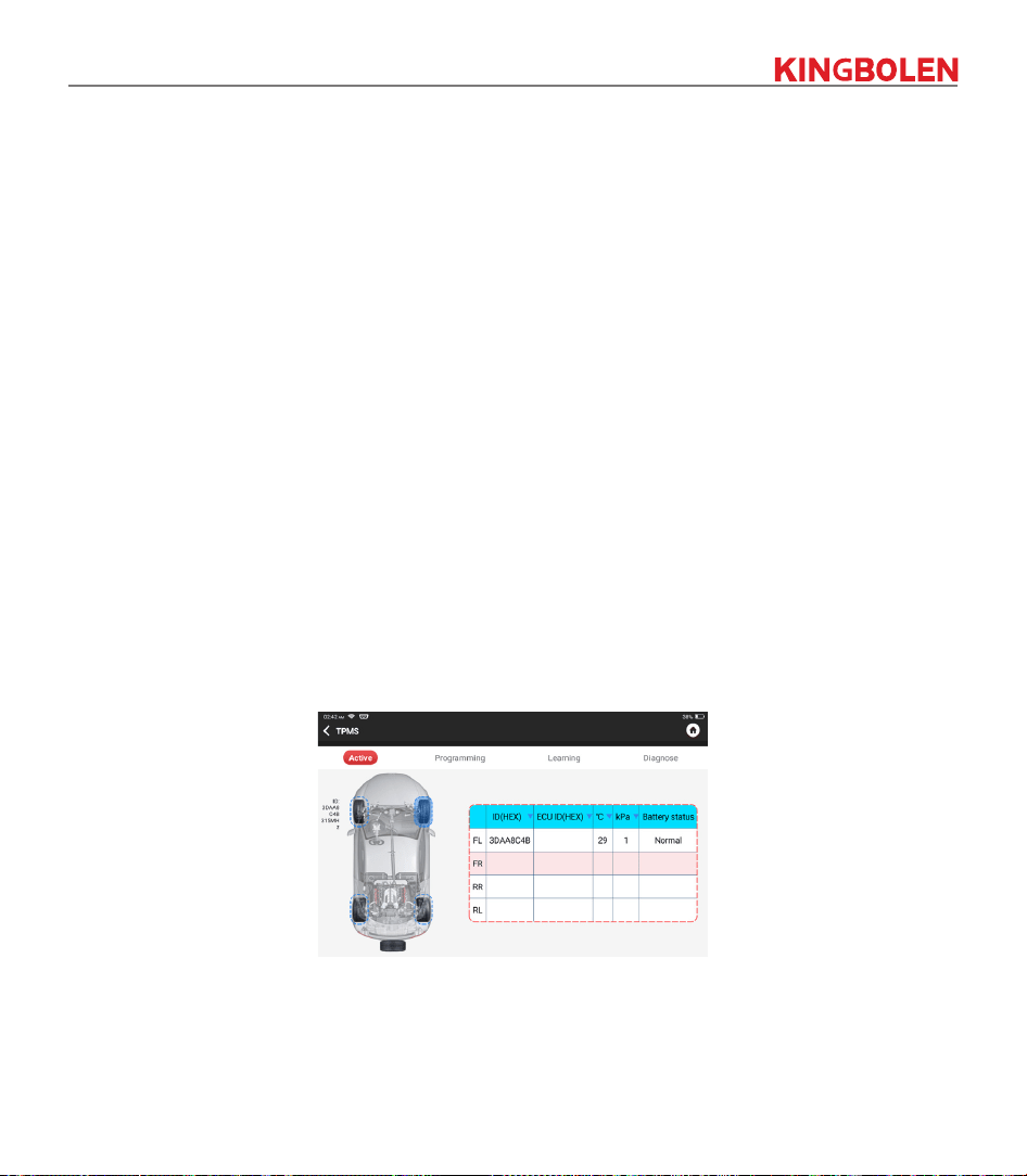
3.5 TPMS Diagnosis
The device can work with wireless tire pressure diagnostic tool (optional accessory) to achieve the features
of TPMS activation, programming and learning.
A. Activation: to activate the sensor's ID, wheel pressure, sensor frequency, tire temperature and battery
status.
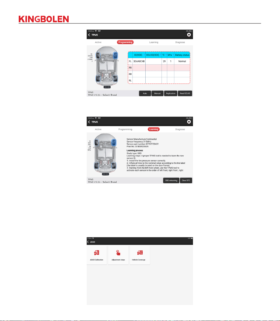
B. Programming: to program sensor data to a new KINGBOLEN sensor, so as to replace a sensor that is
in low battery and does not function properly. There are three sensor programming methods available:
Automatic, manual, and via activation replication.
27
C. Learning: to write the sensor ID into the vehicle ECU for sensor identication.
3.6 ADAS
Advanced driver assistance systems (ADAS) is an electronic component in vehicles that include a variety
of vehicle safety functions such as automatic emergency braking (AEB), lane departure warning (LDW),
lane keeping assistance, blind spot elimination, night vision cameras, and self-adaptive lighting. For this
function, it is necessary to use the ADAS calibration device produced and activate ADAS software.
Notes: ADAS function requires additional hardware (optional), which needs to be purchased.
28
3
.
7
Module
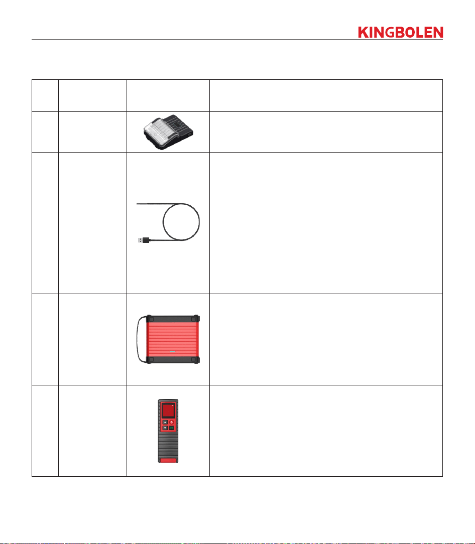
The device supports optional function modules, list as below:
S/N Name Image Description
1
Printer
Thermal printer, can be used with the device or moduledock,
quickly print diagnostic reports anytime and anywhere.
2
Video Scope
Ultra long custom coil pipeline design, flexible bending
with durable materials, suitable for a variety of complex
environments. Multiple uses with 3 kinds of special
connectors (Hook, side view mirror, magnet). Supports 720P
HD image. With 6 auxiliary lights for brighter light, it is easy
to use in dark environment.
Application scenario:
1. Engine combustion chamber inspection;
2. Engine internal carbon deposit inspection;
3. Three-way catalytic inspection;
4. Air-conditioning pipeline inspection;
5. Vehicle corners that are not easy to detect, such as falling
screws, or water leakage, cracks, and foreign objects.
3
Scope Box
Equipped with 4 channels 100MHz bandwidth, sampling
rate reaches up to 1GS/s. Combined with the device screen
to achieve full touch control operation. Special automatic
maintenance and detection menu and high-definition
waveform display make it more convenient to use.
Application scenarios: Scopebox can accurately determine
the problems of sensors, actuators, control modules or
circuits.
4
Wireless TPMS
Work with the device to complete tire pressure diagnosis
related functions.
Application scenario:
1. Read tire pressure information such as pressure,
temperature, and battery status;
2. Replace the sensor for programming;
3. Change the position of the tire or other abnormalities that
require sensor learning
3.8 Remote Assistance
In this function, you can request remote assistance through third-party software. By sending your device
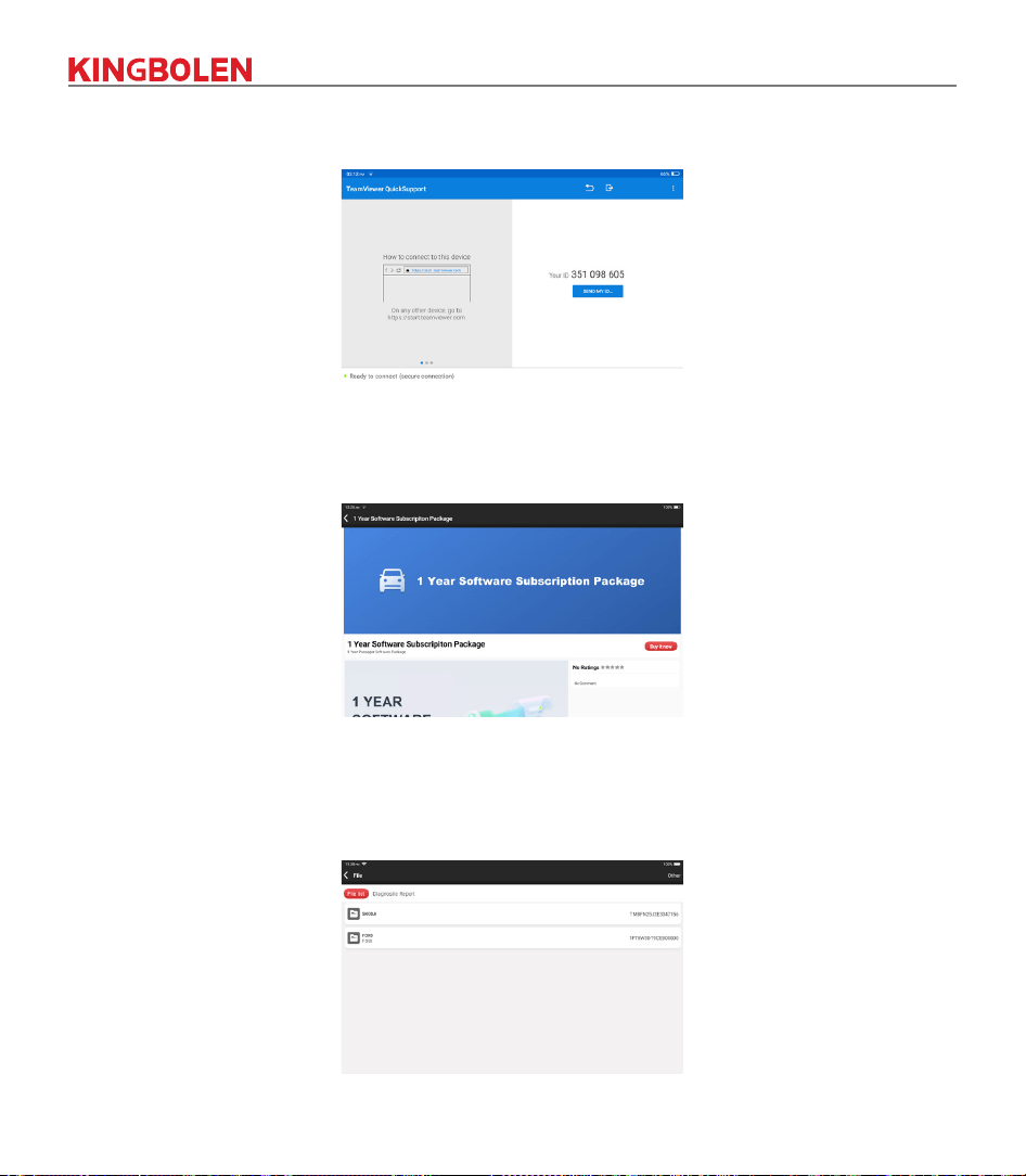
29
ID number to the remote technician or after-sales personnel, you can authorize the other party to remotely
operate the device, so as to guide you to the problems encountered in the process of using the device.
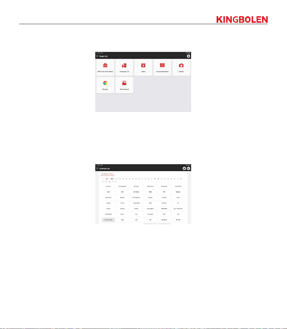
3.9 Store
In the store, vehicle diagnostic and maintenance software can be bought. Each diagnostic software has a
detailed function introduction. All hardware products can also be purchased online
.
3.10 File
It is used to record and establish the le of the diagnosed vehicles. The le is created based on the vehicle
VIN and check time, including all VIN-related data such as diagnostic reports, data stream records and
pictures.
30
3.11 Repair Info
Tap "Repair Info" on the homepage, the following page will appear.
3.11.1 OBD Fault Code Library
You can enquire the denition of OBD fault codes.
3.11.2 Coverage List
You can enter the Vehicle brand, model, year and other information to enquire the support functions and
diagnostic system.
3.11.3 Learning materials
You can view the operation playback of the special functions of each brand model, to help users study the
operation of the special functions online without connecting the vehicle.
3.11.4 User Manual
You can nd the E-Manual in here.
3.12 Update
In order to let you enjoy better functions and upgrade services, we recommend you make software
upgrades irregular. When there is a newer software version, the system will remind you to upgrade.
Tap "Software Upgrade" to enter the upgrade center. There are two function tabs on the upgrade page:
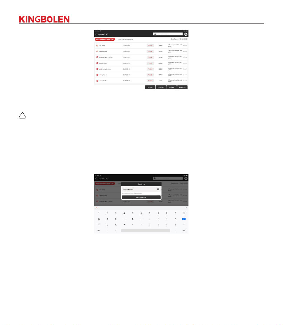
31
Upgradeable software: A list of software that can be upgraded to newer versions.
Upgraded software: A list of software that has been downloaded.
!
Note: During the upgrade, please keep normal network connection. Upgrade many software may take a few
minutes, please wait.
If you need to cancel certain software, please enter setting
->
diagnostic software clear
->
remove software
to operate.
Renewals:
Please contact your local dealer to purchase a K-code card when your vehicle model package
expires.
Tap "Renewals" and enter the K-code and tap OK.
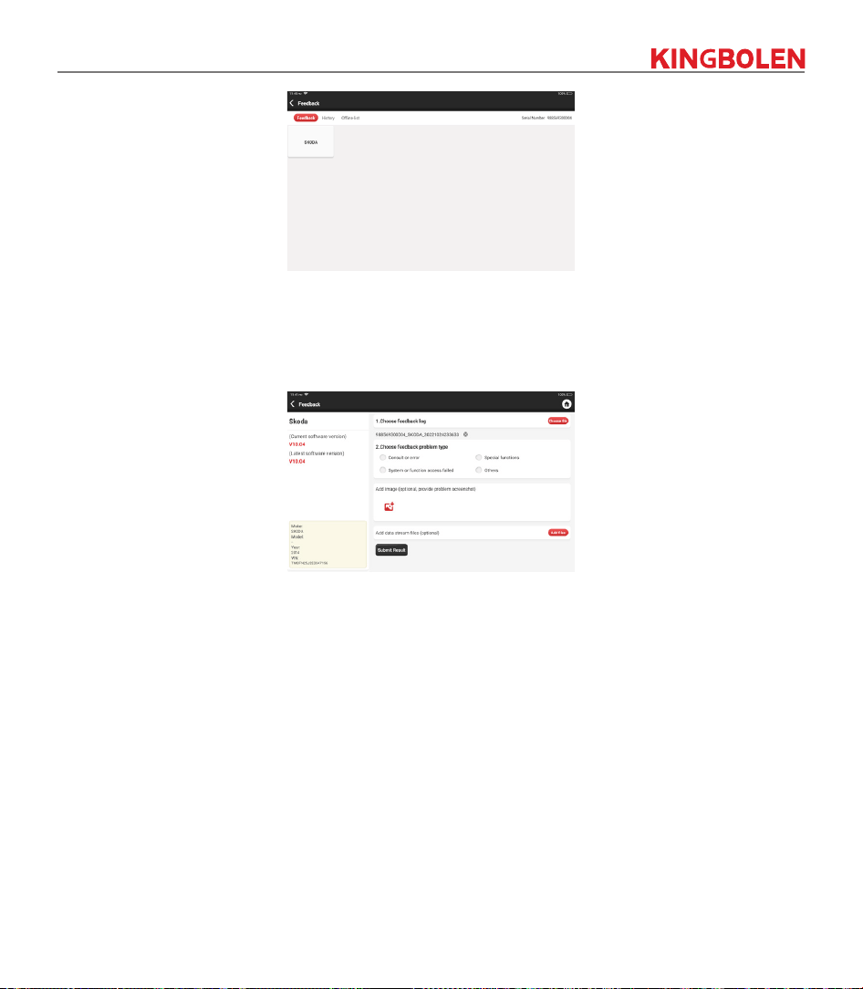
3.13 Feedback
If you encounter an unresolved problem or diagnostic software bug during diagnosis, you can revert the
most recent 20 test records to KINGBOLEN Team. When we receive your feedback, we will analyze
and troubleshoot it in a timely manner, to improve the quality of our products and user experience. Tap
Feedback
, the below pop-up message will appear:
32
Tap
OK
to enter the vehicle diagnostic feedback selection screen. There are three options:
Feedback
: Tap to show the list of all tested vehicle models.
Tap on the target diagnostic record, lling out some information and tap "Submit Result". After submission,
our engineers will be able to analyze the data from the diagnostic report.
History
: Tap to view all diagnostic feedback reverted and the processing progress.
Oine List
: Tap to display all diagnostic feedback logs which have not been submitted successfully due to
network failure. Once the tablet gets a stable network signal, it will be uploaded to the server automatically.
On the Diagnostic Feedback page, tap the diagnostic record of certain vehicle model or special function to
next step.
Tap Choose File to open the target folder and choose the desired diagnostic logs. Choose the failure type
and ll with the detailed failure description in the text box, and leave your telephone or email address. After
inputting, tap Upload Logs to revert feedback to us.
We will follow up your feedback as soon as we receive your diagnostic feedback, please keep an eye on
the progress and results of your diagnostic feedback in Diagnostic Feedback History.
4. User Info
33
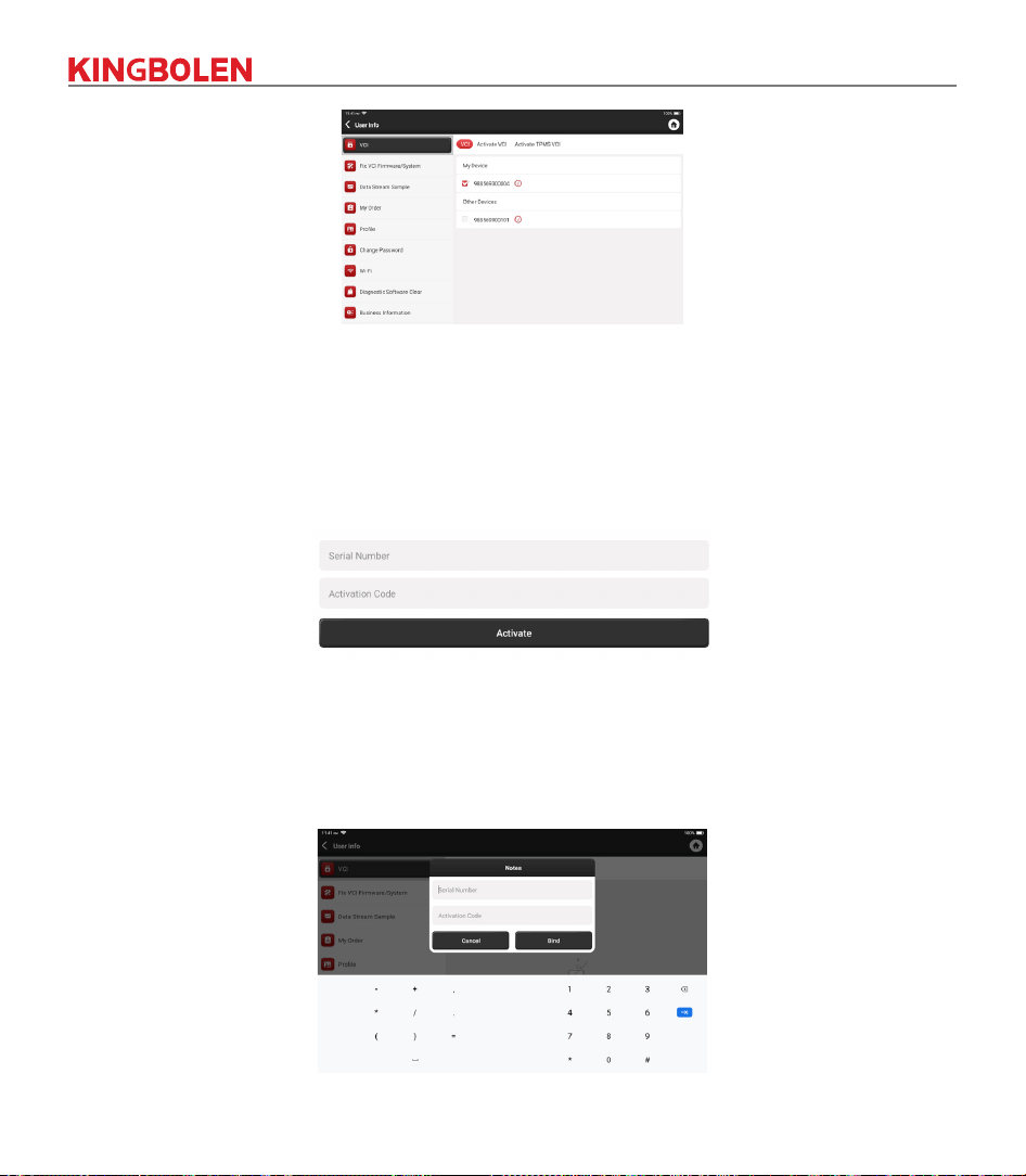
4.1 VCI
If several VCI connectors are registered on the device, this option allows you to choose one from those.
4.2 Activate VCI
This step allows you activate a new VCI connectors or get help. Input the Serial Number and Activation
Code, and then tap “Activate” to activate it.
Once the VCI connector is activated, the serial number of it will be displayed in the list which located in the
VCI.
4.3 Activate TPMS VCI
This step is for binding the Tire Pressure Monitoring System.
34
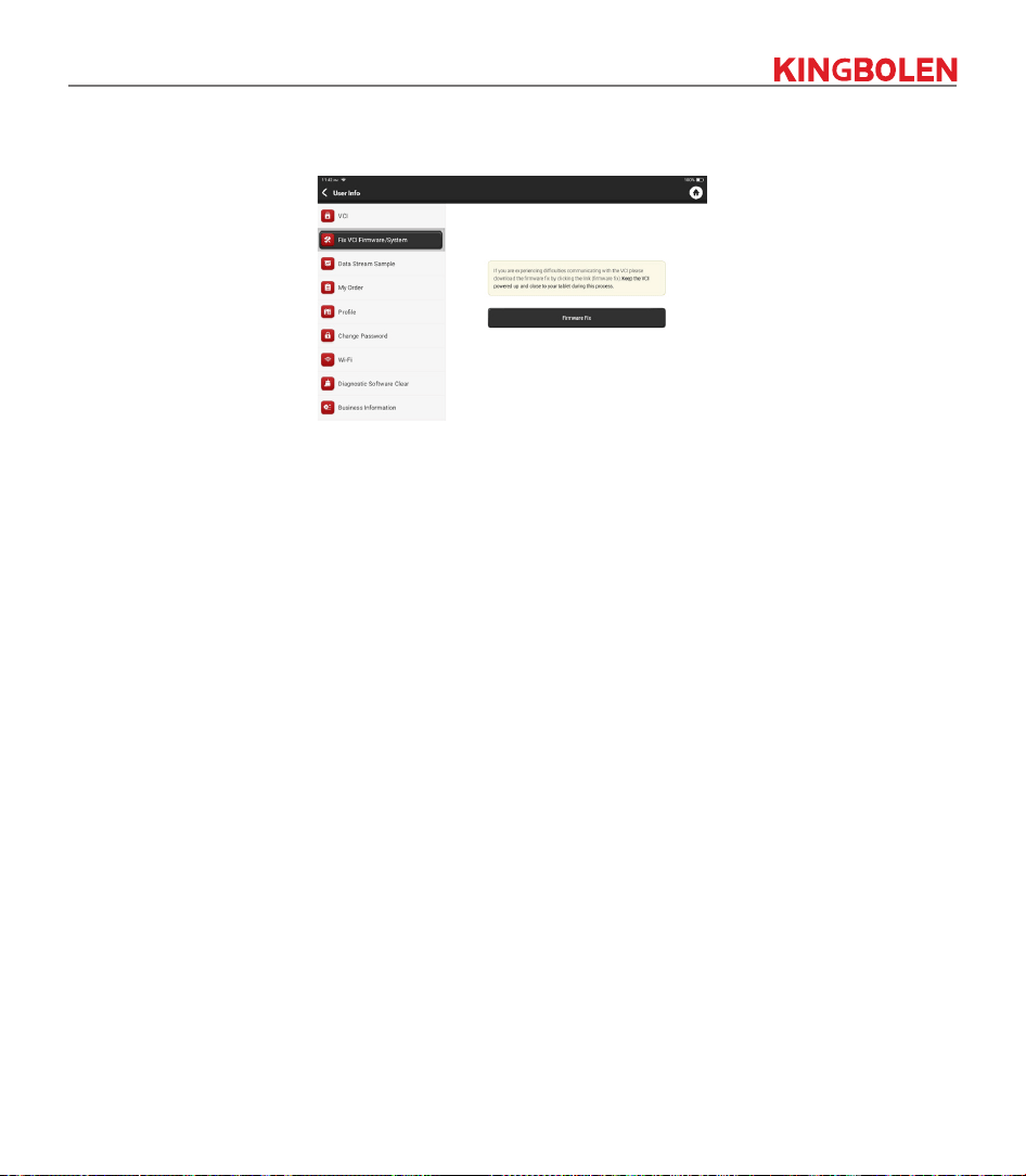
4.4 Fix VCI rmware/system
Use to repair the VCI rmware. During the repair, please don’t power o or switch interfaces.
4.5 Data Stream Sample
This feature allows you to manage the recorded data stream sample les.
4.6 My Order
Use to manage order details.
4.7 Prole
Use to set and manage personal information.
4.8 Change Password
This item allows you to modify your login password.
4.9 Wi-Fi
Set up Wi-Fi networks that can be connected.
4.10 Diagnostic Software Clear
This option can clear some unused diagnostic software and free up the storage space.
4.11 Business Information
Add the information of the workshop, to which the scanner belongs, and it will be displayed to the
customers in the diagnostic report.
4.12 Customer Management
Manage information of all customers, who conduct vehicle diagnostic on this equipment and display in
turn.
35
4.13 Diagnostic Record
You can check the diagnostic history in here.
4.14 Photo Album
This module saves the screenshots.
4.15 Screen Recorder
This module saves the screen recordings.
4.16 Clear VCI Data
Clearing VCI data will delete all download software, diagnostic records, and user setting, etc., which are
associated with the VCI.
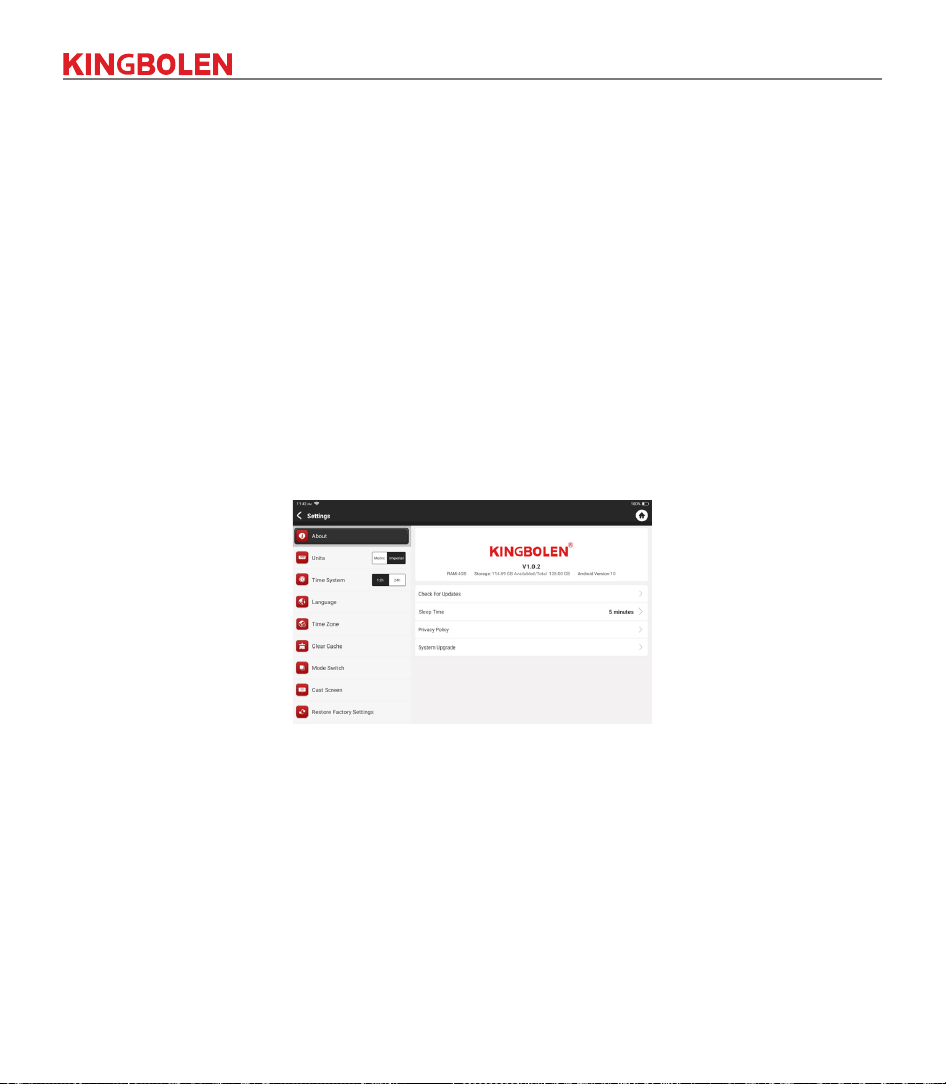
4.17 Settings
In here, we would be able to check the version, system, storage and other fundamental settings of the
device.
4.17.1 Check for Updates
It is for checking the version of the device and update it if it is necessary.
4.17.2 Sleep Time
This is used to set up the sleep time. If the device is not operated within the sleep time limit, the device will
automatically turn o the screen.
4.17.3 Privacy Policy
You can nd the seller’s service information in here.
4.17.4 System Upgrade
To check the latest Android system version and upgrade it if it is necessary.

36
4.17.5 Units
It controls the data unit in the device. Choose the one that you are accustomed to reading.
4.17.6 Clear Cache
To clear all the storage software, account, information, setting, and all the records of the device to save the
space. PLEASE USE IT WITH CAUTION.
4.17.7 Mode Switch
When connecting with other modules, HOST MODE must be used.
4.17.8 Restore Factory Settings
Factory Reset, delete all data and restore the original settings. PLEASE USE IT WITH CAUTION.
4.18 Hotkey Setting
Including: Wi-Fi, Bluetooth, screen recording, screenshot, screen ip, brightness and sound.
37
5.FAQ
Q: Can I use the same type of charger to charge the tablet?
A: No, please use original charger. Our company is not responsible for any damage and economic loss
caused by using charger, which is not provided by KINGBOLEN.
Q: How to save power?
A: Please turn o the screen while the device isn’t used, set a shorter standby time, and decrease the
brightness of the screen.
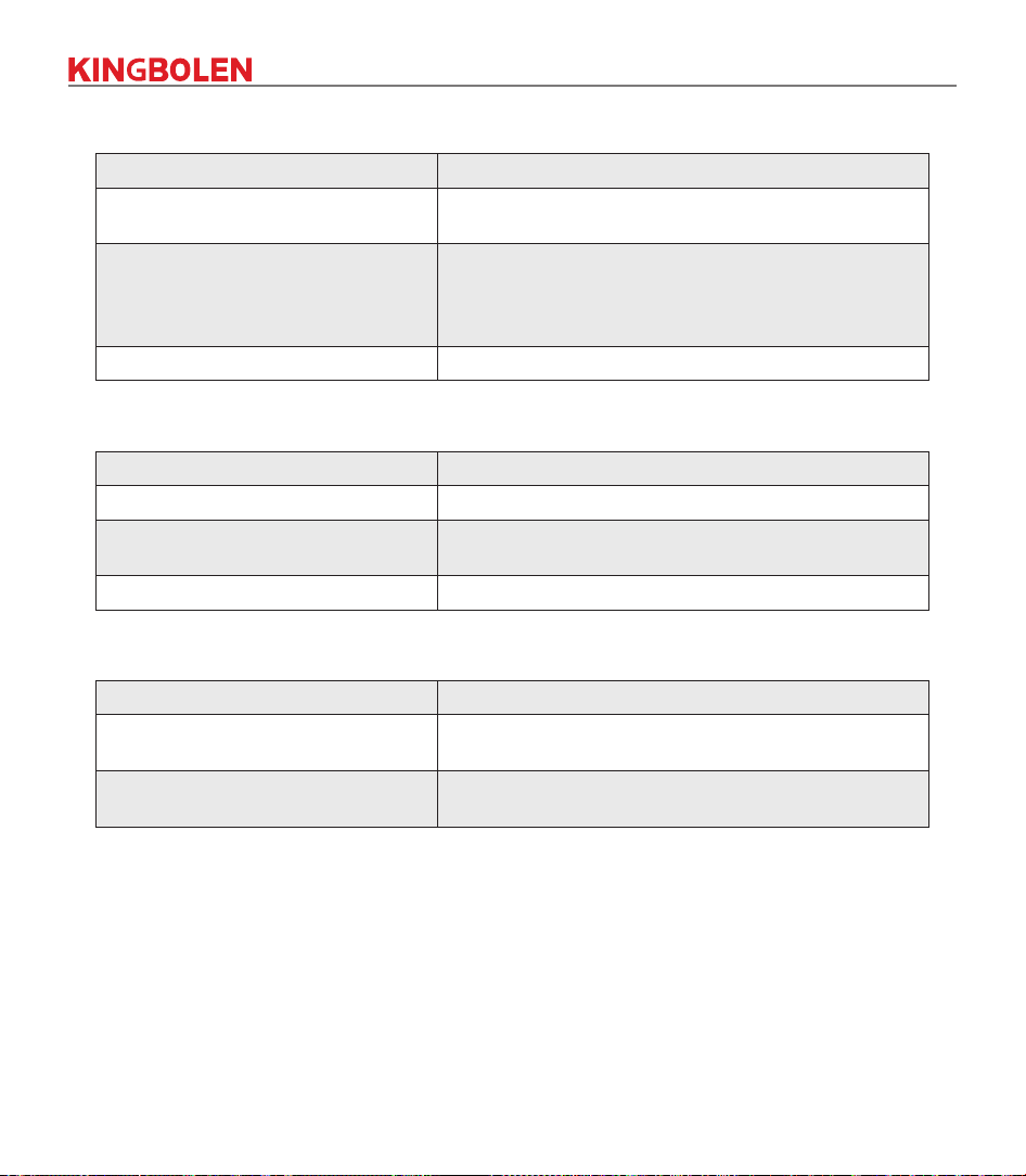
Q: Why the tablet cannot be turned on after charging?
Possible reasons Solutions
Battery loss caused by the device not
using for a long time.
Charge it for more than 2 hours before turning it on.
Problem of Charger.
If there is a quality problem, please contact the dealer or
after-sales service of KINGBOLEN.
Q: Why can’t make register?
Possible reasons Solutions
The device is not connected to the
network.
Please make sure the network is connected.
Notes that your email has been
registered.
Register with another e-mail account or log in with
the username registered by e-mail (If you forget the
username, you can retrieve it by e-mail).
The email didn’t receive the verication
code during the registration.
Check if the e-mail is correct and get the verication code
again.

38
Q: Why can’t I log in?
Possible reasons Solutions
The device is not connected to the
network.
Please make sure the network is connected.
The username or password is
incorrect.
Check the username and password.
Contact KINGBOLEN after-sales service or regional
sales to retrieve the user name and password.
Server problem. Server maintenance, please try again later.
Q: Why can't I activate the device?
Possible reasons Solutions
The device is not connected to the
network.
Please make sure the network is connected.
The serial number and activation code
are inputted wrong.
Check the serial number and activation code and make
sure they are correct (Serial number 12 digits, activation
code 8 digits).
The activation code is invalid.
Contact KINGBOLEN after-sales service or regional
sales.
Notes that the conguration is empty.
Contact KINGBOLEN after-sales service or regional
sales.
Q: Why was the device not activated during the software update?
Possible reasons Solution
The VCI connector may not be
activated during registration.
Use the serial number and activation code to activate the
connector.
Steps are as follows: Click [Settings]
->
[Activate VCI]
Enter the correct serial number and activation code in the
interface, and click [Activate].
39
Q: Why the software upgrade failed?
Possible reasons Solutions
The device is not connected to the
network.
Check the network connection.
The username or password is wrong
The device has not enough memory.
Check the username and password.
Uninstall irrelevant applications and delete uncommonly
used vehicle software (enter setting
->
diagnostic
software clear
->
remove software to operate).
Server problem. Server maintenance, please try again later.
Q: Why is there no power in the VCI dongle after connecting to the vehicle’s DLC port?
Possible reasons Solutions
Poor contact of vehicle’s DLC port. Plug out the VCI dongle, and then plug it in again.
Too low voltage of the vehicle battery.
• Recharge the vehicle battery.
• Replace the vehicle battery if it is damaged.
Damage of the VCI dongle. Contact KINGBOLEN after-sales service to get support.
Q: Why can't tablets establish a connection with the VCI dongle?
Possible reasons Solutions
Poor contact of the VCI dongle.
• Plug out the VCI dongle, and then plug it in again.
• Perform the VCI Bluetooth pairing again.
The rmware is damaged.
Enter the settings and tap “Fix Connector Firmware/
System” to x the rmware.
Q: Why is the communication error with the vehicle ECU displayed?
A: Please conrm:
Whether the VCI is correctly connected and whether the vehicle ignition switch is ON.
If all are normal, send vehicle production year, model and VIN number by Feedback feature.
Q: Why can't I access the vehicle ECU system?
A: Please conrm:
Whether the vehicle is equipped with the system, whether the VCI is correctly connected, and whether
the vehicle ignition switch is ON.

40
Q: What if the connector is lost?
A: Contact KINGBOLEN after-sales service or regional sales.
Q: What if the downloaded diagnostic software is inconsistent with the serial number?
A: There are several connectors registered under the equipment account, and the serial number of right
connector has not been selected.Enter the settings-[VCI] and select the right serial number of
connector. Delete the problematic software, then enter the upgrade center to download the diagnostic
software again.

41
Warranty Terms
▪ This warranty applies only to users and distributors who purchase KINGBOLEN products through
normal procedures.
▪ Within one year from the date of delivery, KINGBOLEN warrants its electronic products for damages
caused by defects in materials or workmanship.
▪ Damages to the equipment or components because of abuse, unauthorized modication, use for non-
designed purposes, operation in a manner not specied in the instructions, etc. are not covered by this
warranty.
▪ The compensation for dashboard damage caused by the defect of this equipment is limited to repair or
replacement. KINGBOLEN does not bear any indirect and incidental losses.
▪ KINGBOLEN will judge the nature of the equipment damage according to its prescribed inspection
methods. No agents, employees or business representatives of KINGBOLEN are authorized to make
any conrmation, notice or promise related to KINGBOLEN products.
SHENZHEN KINGBOLEN ELECTRONIC TECHNOLOGY.,LTD
Service Line: (+86)0755-23445106
Customer Service Email: [email protected]
Ocial Website: www.kingbolen.com
Youtube: Kingbolen auto scanner center
Facebook: @kingbolen.fans
Instagram: @kingbolen.fans
Products tutorial, videos, Q&A and coverage list are available on KINGBOLEN ocial website.