- 15 - - 16 -- 14 -- 13 -- 12 -- 11 -- 10 -- 9 -
4) System Info:
Display the device hardware information, software information, release d-
ate and serial number, etc.
3) Self-test:
-- Display Test (Used to check the displa y screen.)
-- Keyboard Test (Verifies that the keys are working correctly.)
2) Unit:
Changes units of measurement to display Metric System and English System.
1) Languages:
Allows the user to change the system language of the tool. Default langu-
age is English.
3.4 Settings
Display battery condition, Max value & Min value by graph in real ti-
me.
3.3 Battery
Looks up definitions of DTCs stored in scan tool, and shows the possible
causes of the DTC. (Not every DTC with possible causes reason)
3.2 DTC Lookup
- 8 -
9) Component Test:
Tool will display a list of components and their locations on the vehicle. T-
his function will always appear on the Main Menu. This selection will app-
ear on the Diagnostic Menu only when the tool has a list of component loc-
ations for the currently selected vehicle.
8) O2 Sensor Test:
Display oxygen sensor monitoring test results from the vehicle’s memory,
the O2 Monitor Test is not an ON-DEMAND Test.
7) On-Board Monitoring:
Scan tool controls the operation of vehicle components, tests or systems.
-- When the monitor`s status is:
OK - The vehicle's monitors have run and completed their diagnosis
and testing.
INC (Incomplete) - The vehicle's monitors have not yet run and com-
pleted diagnosis and testing.
N/A (Not Applicable) - vehicle does not support that monitor.
HTR
EVAP
AIP
O2S
EGR
MIS
FUE
CCM
CAT
HCAT
I/M Readiness
On
SPARK
2
2
MIL
DTC
IGN
PdDTC
- 7 -
No.
Name
Abbre-
viation
Malfunction Indicator
Lamp (MIL) Status
Diagnostic Trouble
Code
Misfire Monitoring
Fuel System Monitor
Comprehensive Com-
ponents Monitor
Catalyst Monitor
Heated Catalyst
Monitor
No.
Name
Abbre-
viation
Ignition Key
Pending DTC
Evaporative System
Monitor
Air Conditioning
Refrigerant Monitor
Oxygen Sensor
Monitor
Heated Catalyst
Monitor
Exhaust Gas Recircu-
lation System Monitor
-- Abbreviations Explanation of IM Readiness:
-- There are two types of I/M Readiness tests:
a. Since DTCs is Cleared (shows status of the monitors since the DTCs we-
re last cleared.)
b. This Drive Cycle (shows the status status of monitors since the start of the
current drive cycle.)
NOTE:
* To review I/M Readiness status, make sure that the ignition key is switc-
hed to ON with the engine off.
* Not all monitors are supported by all vehicles.
6) I/M Readiness:
Display a snapshot of the state of the vehicle’s OBDII Monitors.
at identify the software version in the vehicle’s control module (s).
The tool also displays In-Use Performance Tracking of important readine-
ss monitors.
- 6 -
5) Vehicle Info.:
Scan tool displays the vehicle’s VIN number, Calibration ID (s) and CVN th-
4) Freeze Frame:
Display a snapshot of operating conditions at the time of an emission relat-
ed fault.
-- Playback:
Choose the record slot to playback the live data, switch frame by an-
d key.
-- Record:
Record the PIDs frame, selecte PIDs by key, enter the record page
by key. Select the "Memory Slot”and start recording.
-- Graph Display:
Show the live data via graph mode. selecte PIDs by key, enter the g-
raph by key switch the PIDs by and key.
-- All Datastream:
Views vehicle Parameter ldentification Data ( PIDs ) in real time. PIDs are
displayed in textual or graphic format when available.
3) Live Data:
The live Data menu allows you to view the recording and playback of real
time PID data from the electronic control module.
* In live data menu, the selected items can be set-to-top by pressing and
holding the key for 3 seconds.
2) Erase Codes:
Delete DTCs from the vehicle's computer system’s memory.
1) Read Codes:
Reads DTCs from the vehicle's computer with KOEO or KOER.
3.1 Diagnosis Functions
- 5 -
- Function is only in the three-level menu.
+ Function is only in the secondary menu.
The Function is only in the main menu.
+ System Info.
- Keyboard Test- Display Test
+ Self-test
+ Data Logging
- English- Metric
+ Unit
- 繁體中文
- Pусский
- Español
- 日本語
- English
- Italiano
- Deutsch
- Français
- Português
+ Languages
Settings
Battery
DTC Lookup
+ Read Codes
+ Erase Codes
- All Datastream
- Graph Display
- Record
+ Freeze Frame
+ Vehicle Info.
+ I/M Readiness
+ O2 Sensor Test
+ Live Data
- Playback
+ On-Board Monitoring
+ Component Test
Diagnosis
The Main Menu and Diagnostic Menu are broken down into the foll-
owing menus:
3. Tool Menu
- 4 -
6. Perform Quick Test:
By using the , , , or keys to select to Diagnosis M-
enu by pressing key to ENTER.
5. The tool will attempt to identify the vehicle. If successful,it will display the
information about the recognized vehicle. If the vehicle cannot be recogni-
zed,a menu will be shown for you to select the vehicle manually.
4. Plug the OBDII connector into the Data Link Connector.
3. Turn the ignition switch to the ON position. Do not start the engine.
2. If necessary, remove the cover from the DLC.
1. Locate the OBDII Data Link Connector under the steering column. If the c-
onnector is not there, there should be a label indicating the whereabouts of
the connector.
2.2 Connect The Tool
If unsure about location of DLC, check
vehicle’s service manual or reputable
service center for the location
Choose a location (under driver side
dash, or under steering wheel) and
use that description in both places.
2.1 Locating Data Link Connector
2. Using Your Scan Tool
- 3 -
6. Net Weight: 0.19kg (0.42lb), GW: 0.23kg (0.51lb).
5. Product Size: 137 × 79 × 22 mm (5.4"×3.1"×0.9").
4. External Power: 9.0V to 16.0V power provided via vehicle battery.
3. Storage Temperature: -20°C to 70°C (-4°F to 158°F).
2. Operating Temperature: -10°C to 40°C (14°F to 104°F).
1. Display: 320 x 240 pixel display with TFT color screen.
1.2 Specifications
13. Up + Down Keys - Screen capture function. (The device stores up to 10
pictures.)
12. USB Interface - Connecting the USB to the computer, the removable di-
sk will be displayed. Simply copy and paste the upgrade file into the remo-
vable disk to complete the upgrade.
11. Right Scroll Key - Moves right through menu and submenu items in m-
enu mode. When more than one screen of data is retrieved, moves right
through the current screen to the next screens for additional data.
10. Enter Key - Confirms a selection (or action) from a menu.
9. One-key I/M Readiness - Quick checks emission readiness status and
drive cycle verification.
8. Right Scroll Key - Moves right through menu and submenu items in me-
nu mode. When more than one screen of data is retrieved, moves right th-
rough the current screen to the next screens for additional data.
7. Left Scroll Key - Moves left through menu and submenu items in menu
mode. When more than one screen of data is retrieved, moves left through
the current screen to the previous screens for additional data.
6. Back Key - Cancel a selection (or action) from a menu or returns to the
menu. lt is also used to exit DTC lookup screen.
ode. When more than one screen of data is retrieved, moves up through t-
he current screen to the previous screens for additional data.
- 2 -
5. UP Scroll Key - Moves up through menu and submenu items in menu m-
4. One-key DTC - Looks up Pending Codes stored in the scan tool.
3. One-key VIN - Display vehicle identification number.
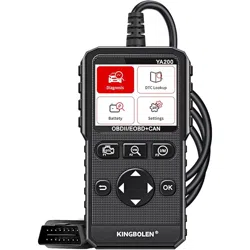
2. LCD Display - Visual display of information to the user. 320 × 240 Pixel
display with TFT color screen.
1. OBDII Connector - Connects the scan tool to the vehicle’s Data Link Co-
nnector (DLC).
12
11
10
9
8
7
6
5
4
3
2
1
The scan tool is designed for easy use. All menus and lists operate
the same way.
1.1 User Interface
1. General Scan Tool Information
- 1 -
- 10 -
- 9 -
- 9 -
- 9 -
- 6 -
- 5 -
- 4 -
- 4 -
- 3 -
- 2 -
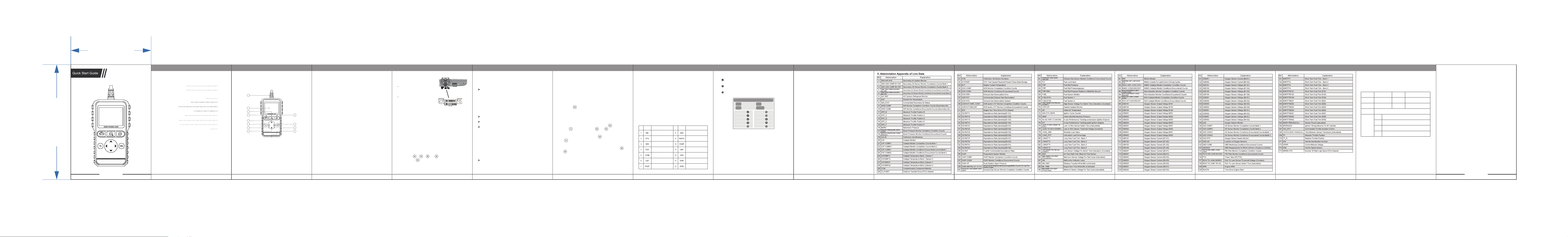
4. Abbreviation Appendix of Live Data
3.4 Settings
3.3 Battery
3.2 DTC Lookup
3.1 Diagnosis Functions
3. Tool Menu
2.2 Connect The Tool
2.1 Locating Data Link Connector
2. Using Your Scan Tool
1.2 Specifications
1.1 User Interface
1. General Scan Tool Information
Contents
Version Number: A01 Version Number: A01
65 mm
93 mm
Date
Cause of failure and solution
Order Number
Repair
Records
Address
Name
Purchase Date
Email
Cotact Number
Product Name
If there is any quality problem of the product that needs to be repaired, ple-
ase send this warranty card together with the purchased product back to our c-
ompany to provide after-sales service.
Warranty Statement
Hello ! Thank you for purchasing this product. In order to better serve you,
please read carefully , fill in and properly keep this Guarantee Card after pur-
chasing the product.
5. Guarantee Card
