
1
Solar Powered Wireless Wi-Fi Weather Station
Operation Manual
Table of Contents
1. Introduction
...............................................................................................................
3
2. Warnings and Cautions
..........................................................................................
3
3. Quick Start Guide
....................................................................................................
3
4. Pre-Installation Checkout and Site Survey
..........................................................
4
4.1 Pre Installation Checkout
.................................................................................
4
4.2 Site Survey
.........................................................................................................
4
5. Getting Started
.........................................................................................................
4
5.1 Parts List
.............................................................................................................
5
5.2 Recommend Tools
............................................................................................
6
5.3 Sensor Array Set Up
.......................................................................................
7
5.3.1 Install Wind Vane
...........................................................................................
8
5.3.2 Install Mounting Pole
.....................................................................................
8
5.3.3 Install Batteries
...............................................................................................
9
5.3.4 Mount Weather Station
...............................................................................
10
5.3.5 Reset Button and Transmitter LED
...........................................................
12
5.4 Best Practices for Wireless Communication
..............................................
13
5.5 Display console
...............................................................................................
14
5.5.1 Vertical Desk Stand
...................................................................................
15
6. Display Console Operation
..................................................................................
16
6.1 Screen Display
................................................................................................
16
6.2 Initial Display Console Set Up
......................................................................
16
6.3 Key function
.....................................................................................................
17
6.4 Set mode
..........................................................................................................
19
6.4.1 BEEP:
............................................................................................................
20
6.4.2 MAX/MIN Daily:
...........................................................................................
21
6.4.3 Time / Date
...................................................................................................
21
6.4.4 Pressure
........................................................................................................
21
6.4.5 Light
...............................................................................................................
23
6.4.6 Temperature
.................................................................................................
23

2
6.4.7 Wind speed............................. . . . . . . . . . . . . . . . . . . . . . . . . . . . . . . . . . . . . . . . . . . . . . . . . . . . . . . . . . . . . . . . . . . . . . .23
6.4.8 Rain........... . . . . . . . . . . . . . . . . . . . . . . . . . . . . . . . . . . . . . . . . . . . . . . . . . . . . . . . . . . . . . . . . . . . . . . . . . . . . . . . . . . . . . . . . . . . . . . . . . . . . 23
6.4.9 Moon phase...................... . . . . . . . . . . . . . . . . . . . . . . . . . . . . . . . . . . . . . . . . . . . . . . . . . . . . . . . . . . . . . . . . . . . . . . . . . . . .24
6.5 Alarm mode............................... . . . . .
.......................... . . . . . . . . . . . . . . . . . . . . . . . . . . . . . . . . . . . . . . . .24
6.5.1 View Alarm value...... . . . . . . . . . . . . . . . . . . . . . . . . . . . . . . . . . . . . . . . . . . . . . . . . . . . . . . . . . . . . . . . . . . . . . . . . . . . . . . . . . . . 24
6.5.2 Alarm setting mode:.......................... . . . . . . . . . . . . . . . . . . . . . . . . . . . . . . . . . . . . . . . . . . . . . . . . . . . . . . . . . . 25
6.5.3 Alarm Setting Order:............................... . . . . . . . . . . . . . . . . . . . . . . . . . . . . . . . . . . . . . . . . . . . . . . . . . . . . 26
6.6 Max
/min mode............................. . . . . . . . . . . . . . . . . . . . . . . . . . . . . . . . . . . . . . . . . . . . . . . . . . . . . . . . . . . . . . . . . . . . . 26
6.6.1 Press and release MAX/MIN key to display MAX data.................... . . . . . 26
6.6.2 Press aga in to displ ay min data.............................. . . . . . . . . . . . . . . . . . . . . . . . . . . . . . . . . . . 27
6.7 Calibration mode............................. . . . . . . . . . . . . . . . . . . . . . . . . . . . . . . . . . . . . . . . . . . . . . . . . . . . . . . . . . . . . . . . . 27
6.7.1 Calib
ration Order:........... . . . . . . . . . . . . . . . . . . . . . . . . . . . . . . . . . . . . . . . . . . . . . . . . . . . . . . . . . . . . . . . . . . . . . . . . . . . . . 27
6.8 Other Featu res......................... . . . . . . . . . . . . . . . . . . . . . . . . . . . . . . . . . . . . . . . . . . . . . . . . . . . . . . . . . . . . . . . . . . . . . . . 28
6.8.1 Factory Reset/Clear Memory.................... . . . . . . . . . . . . . . . . . . . . . . . . . . . . . . . . . . . . . . . . . . . . . . . . .28
6.8.2 Register New Transmitter..................... . . . . . . . . . . . . . . . . . . . . . . . . . . . . . . . . . . . .
..................28
6.8.3 Backlight (constant backlight requires operat ion with AC adapter.).... 28
6.8.4 Tendency indicators.................. . . . . . . . . . . . . . . . . . . . . . . . . . . . . . . . . . . . . . . . . . . . . . . . . . . . . . . . . . . . . . . . . . . 28
6.8.5 Wireless Signal Strength Indicator. . . . . . . . . . . . . . . . . . . . . . . . . . . . . . . . . . . . . . . . . . . . . . . . . . . . . . . . . . . 29
6.8.6 Weather forecast................................. . . . . . . . . . . . . . . . . . . . . . . . . . . . . . . . . . . . . . . . . . . . . . . . . . . .
..... 29
6.8.7 Snooze........ . . . . . . . . . . . . . . . . . . . . . . . . . . . . . . . . . . . . . . . . . . . . . . . . . . . . . . . . . . . . . . . . . . . . . . . . . . . . . . . . . . . . . . . . . . . . . . . . . . 31
7. Specification:... . . . . . . . . . . . . . . . . . . . . . . . . . . . . . . . . . . . . . . . . . . . . . . . . . . . . . . . . . . . . . . . . . . . . . . . . . . . . . . . . . . . . . . . . . . . . . . . . . . . . . . . . 31
8. Live Internet Publishing........................... . . . . . . . . . . . . . . . . . . . . . . . . . . . . . . . . . . . . . . . . . . . . . . . . . . . . . . . . . . . . . . 32
8.1 Connecting the Weather Station Consol
e to WiFi......................... . . . . . . . . . . 33
9. Registering with WeatherUnderground.com, WeatherBug.com and
WeatherCloud.net.. . . . . . . . . . . . . . . . . . . . . . . . . . . . . . . . . . . . . . . . . . . . . . . . . . . . . . . . . . . . . . . . . . . . . . . . . . . . . . . . . . . . . . . . . . . . . . . . . . . . . . . .37
9.1 WeatherUnderground.com................................. . . . . . . . . . . . . . . . . . . . . . . . . . . . . . . . . . . . . . . . . . . . 37
9.2 WeatherBug.com........ . . . . . . . . . . . . . . . . . . . . . . . . . . . . . . . . . . . . . . . . . . . . . . . . .
.......................... . . . . . . . . . 43
9.3 WeatherCloud............. . . . . . . . . . . . . . . . . . . . . . . . . . . . . . . . . . . . . . . . . . . . . . . . . . . . . . . . . . . . . . . . . . . . . . . . . . . . . . . . . . . . . .43
10. Maintenance ....... . . . . . . . . . . . . . . . . . . . . . . . . . . . . . . . . . . . . . . . . . . . . . . . . . . . . . . . . . . . . . . . . . . . . . . . . . . . . . . . . . . . . . . . . . . . . . . . . . 44
10.1 Advanced Rain Gauge Cleaning............................ . . . . . . . . . . . . . . . . . . . . . . . . . . . . . . . . . . . . 45
11. Southern Hemisphere - Wind Direction
Re-Calibration................................ 47
12. Troubleshooting Guide..................... . . . . . . . . . . . . . . . . . . . . . . . . . . . . . . . . . . . . . . . . . . . . . . . . . . . . . . . . . . . . . . . . . . 50
3
1. Introduction
Thank you for your purchase of the Solar Powered Wireless WiFi Weather
Station. The following user guide provides step by step instructions for
installation, operation and troubleshooting.
2. Warnings and Cautions
Warning: Any metal object may attract a lightning strike, including your
weather station mounting pole. Never install the weather station in a storm.
Warning: Installing your weather station in a high location may result in
injury or death. Perform as much of the initial check out and operation on the
ground and inside a building or home. Only install the weather station on a clear,
dry day.
3. Quick Start Guide
Although the manual is comprehensive, much of the information contained may
be intuitive. In addition, the manual does not flow properly because the sections
are organized by components.
The following Quick Start Guide provides only the necessary steps to install,
operate the weather station, and upload to the internet, along with references to
the pertinent sections.
Required
Step
Description
Section
1
Assemble and power up the sensor array
5.3.1-5.3.3
2
Power up the display console and synchronize
with sensor array
5.5
5
Mount the sensor array
5.3.4
3
Set date and time on console
6.4.3
4
Calibrate the relative pressure to sea-level
conditions (local airport) on console
6.4.4
6
Reset the rain to zero on console
6.4.8
Optional
7
Configure WiFi
8.1
8
Register and upload to Weather Server
9

4
4. Pre-Installation Checkout and Site Survey
4.1 Pre Installation Checkout
Before installing your weather station in the permanent location, we recommend
operating the weather station for one week in a temporary location with easy
access. This will allow you to check out all of the functions, insure proper
operation, and familiarize you with the weather station and calibration
procedures. This will also allow you to test the wireless range of the weather
station.
4.2 Site Survey
Perform a site survey before installing the weather station. Consider the
following:
1. You must clean the rain gauge every few months and change the
rechargeable batteries every 2-3 years. Provide easy access to the
weather station.
2. Avoid radiant heat transfer from buildings and structures. In general,
install the sensor array at least 5’ from any building, structure, ground, or
roof top.
3. Avoid wind and rain obstructions. The rule of thumb is to install the
sensor array at least four times the distance of the height of the tallest
obstruction. For example, if the building is 20’ tall, and the mounting pole
is 6’ tall, install 4 x (20 – 6)’ = 56’ away.
4. Wireless Range. The radio communication between receiver and
transmitter in an open field can reach a distance of up to 330 feet,
providing there are no interfering obstacles such as buildings, trees,
vehicles, high voltage lines. Wireless signals will not penetrate metal
buildings. Under most conditions, the maximum wireless range is 100’.
5. Radio interference such as PCs, radios or TV sets can, in the worst case,
entirely cut off radio communication. Please take this into consideration
when choosing console or mounting locations. Make sure your display
console is at least five feet away from any electronic device to avoid
interference.
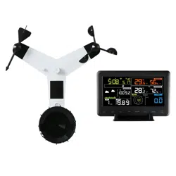
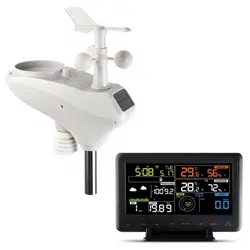
5. Getting Started
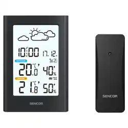
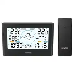
The WiFi weather station consists of a display console (receiver), an all in one
sensor array, and wireless thermo-hygrometer-barometer.
5
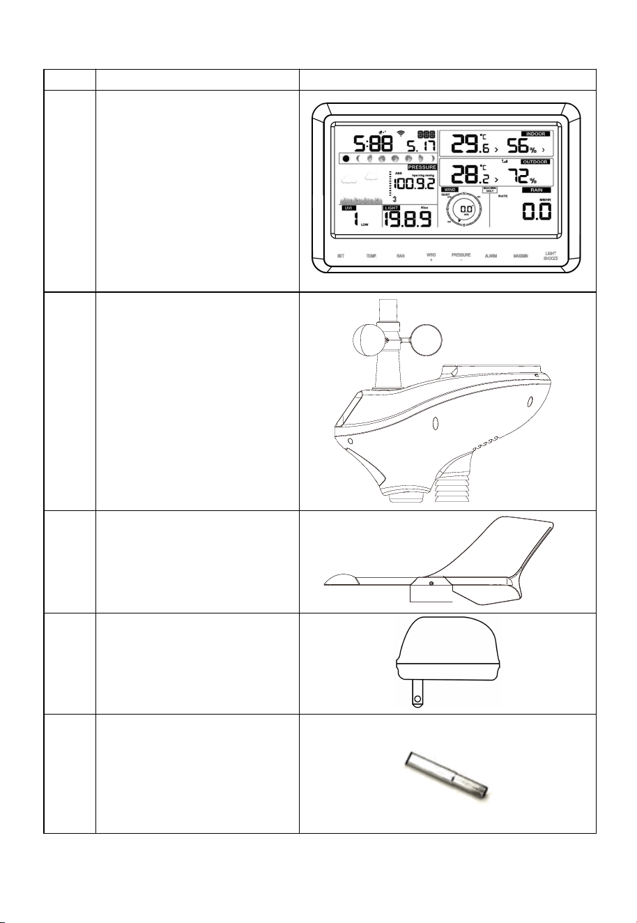
5.1 Parts List
QTY
Item
Image
1 Display Console
Frame Dimensions
(LxWxH): 18.7x11.5x1.9cm
(7.35 x 4.5 x 0.75”)
LCD D imensions (LxW):
15.6x 7.6cm (6.2 x 3”)
1
Sensor Array
1 Wind Vane
1
5V DC Adaptor
1 Pole
6
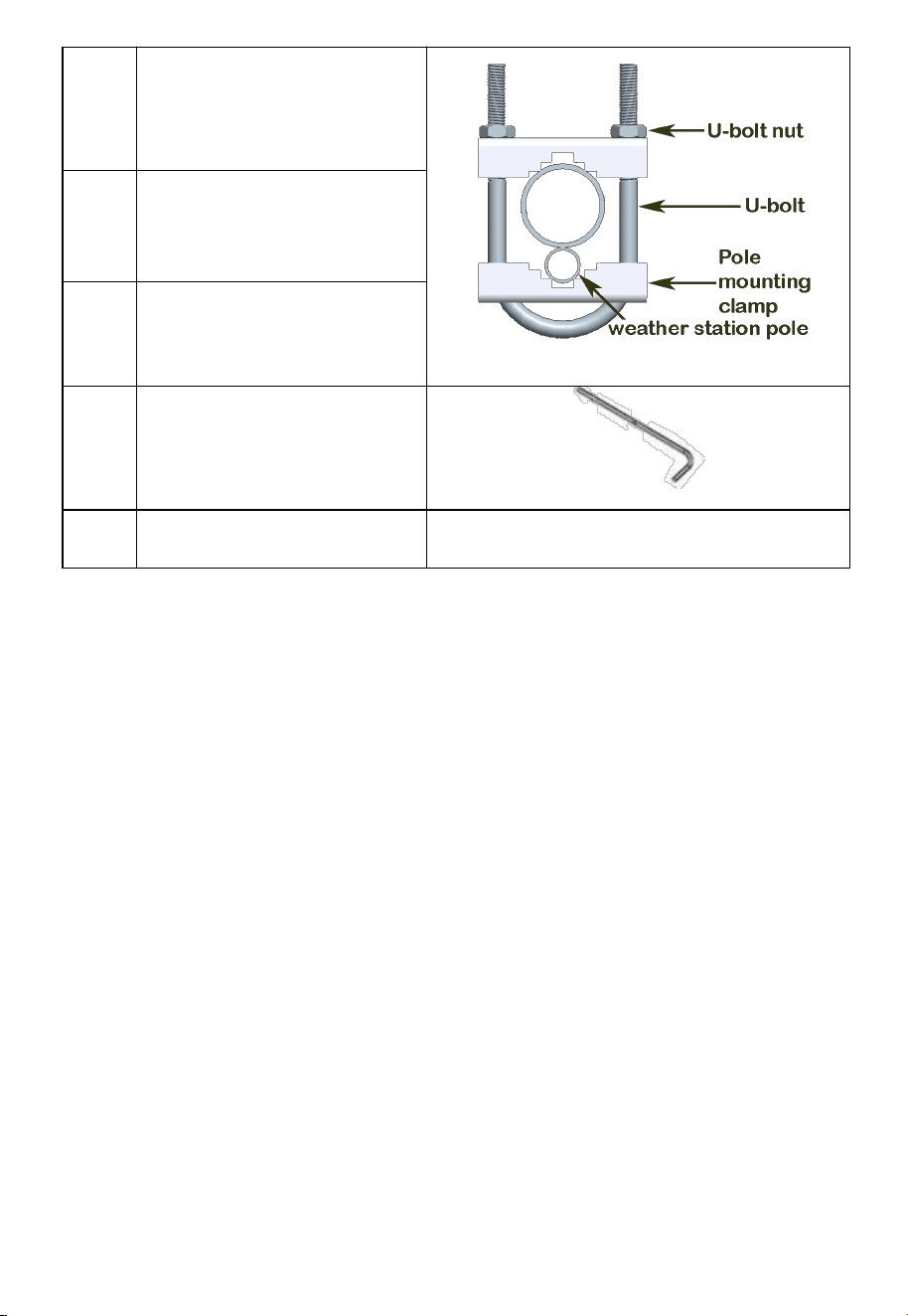
1
Pole mounting U-bolt
2
Pole mounting clamps
2
Pole mounting U-bolt nuts
1
Allen wrench
1
User manual
5.2 Recommend Tools
Precision screwdriver (for small Phillips screw on battery cover door)
Adjustable wrench (for mounting pole)
Compass or GPS (for wind direction calibration)
7
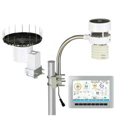
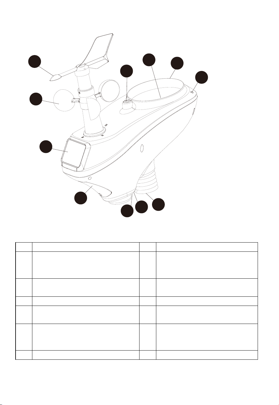
5.3 Sensor Array Set Up
Figure 1
No
Description
No
Description
1 Wind Vane (measures wind
direction)
7 Thermo-hygrometer Sensor
(measures temperature and
humidity)
2
Wind Speed Sensor (measures
wind speed)
8
UV Sensor
3
Solar collector
9
Solar Radiation Sensor
4 Rechargeable battery
compartment
10 Rain Collector (self emptying)
5 LED transmission indicator (turns
on for 4 seconds on power up,
flashes once per 16 seconds)
11 Bubble Level
6
Reset button
10
11
1
2
3
4
5
6
7
8
9
8
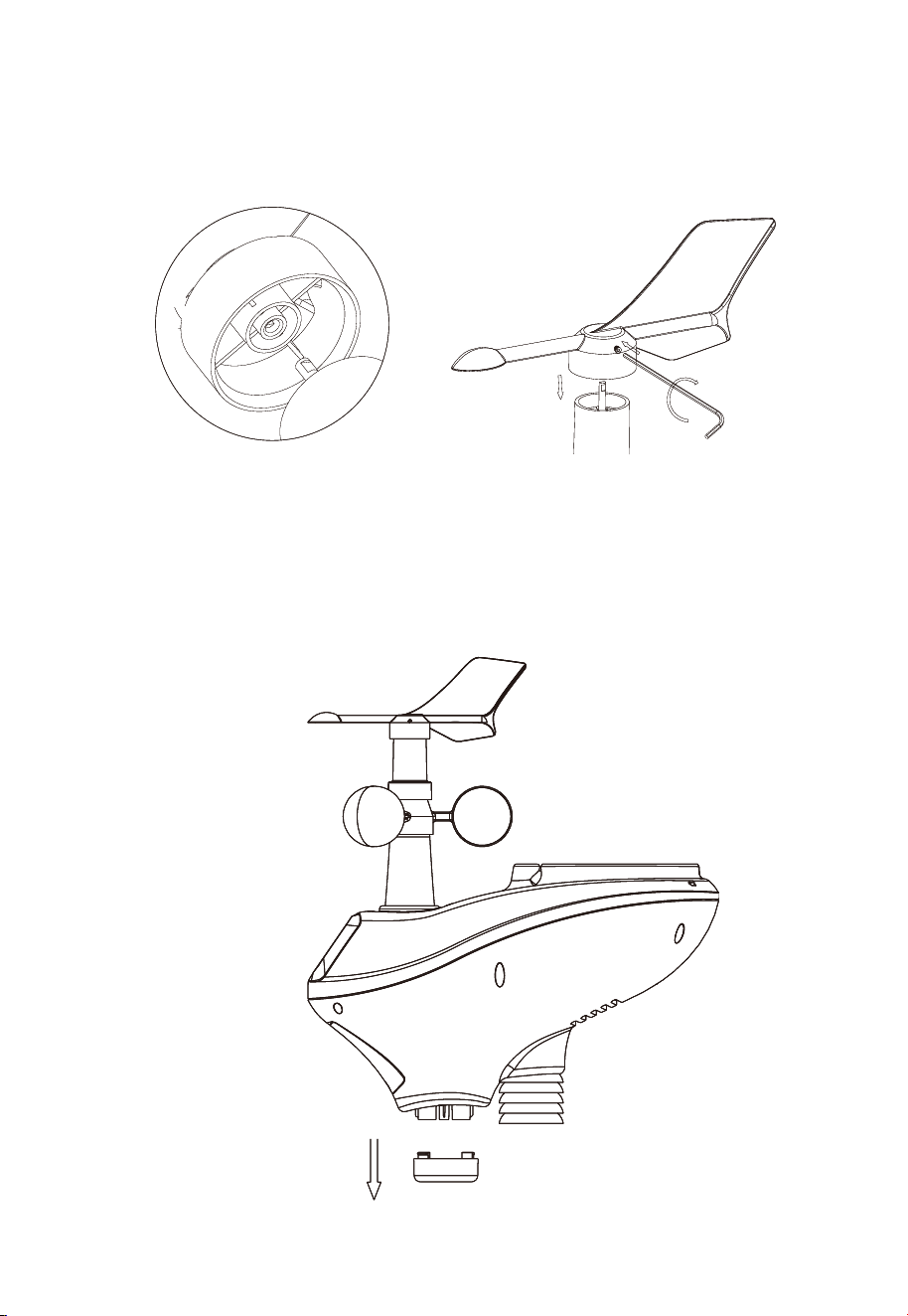
5.3.1 Install Wind Vane
Reference Figure 2. (a) Locate and align the flat key on the wind vane shaft to
the flat key on the wind vane and push the vane on to the shaft. (b) tighten the
set screw with the hex wrench (included).
(a)
(b)
Figure 2
5.3.2 Install Mounting Pole
Reference Figure 3. Remove the mounting pole collar by rotating counter
clockwise.
Figure 3
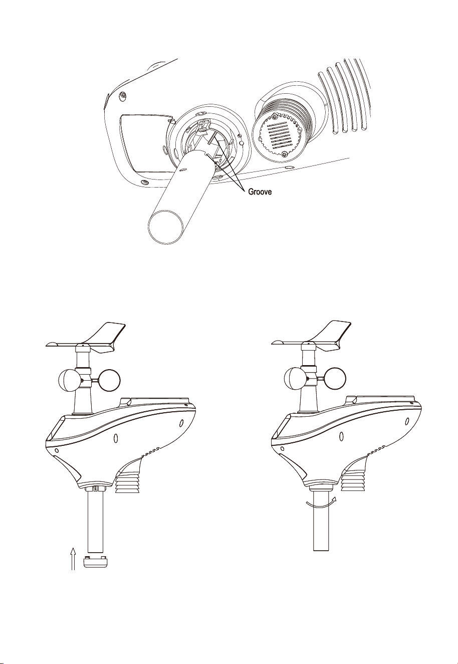
9
Reference Figure 4. Locate and align the groove on the sensor array and
mounting pole.
Figure 4
Reference Figure 5. Turn the mounting pole collar to lock the pole into place by
rotating clockwise.
Figure 5
5.3.3 Install Batteries
Reference Figure 6. Locate the battery door on the bottom of the sensor array.
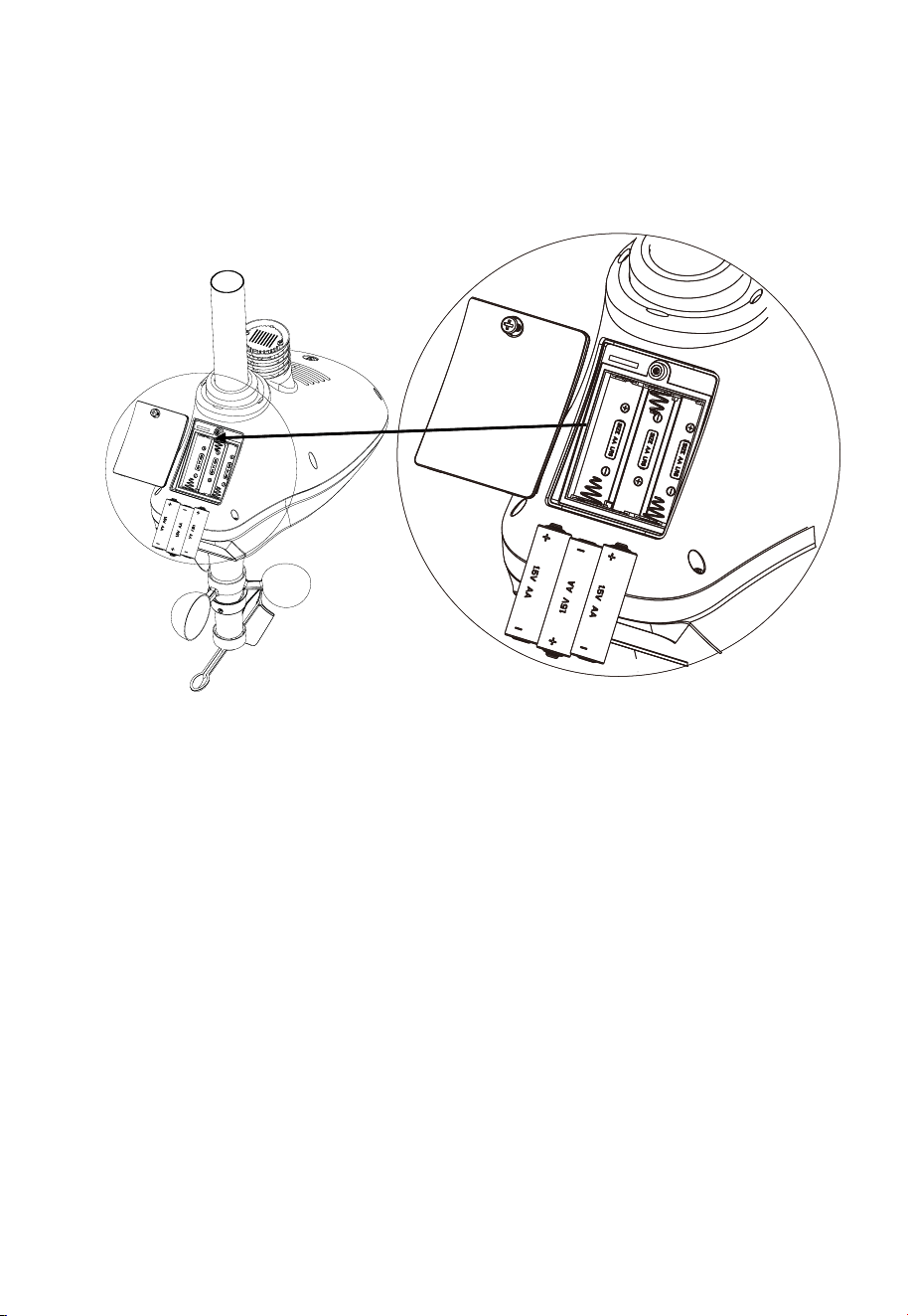
10
Turn the set screw counter clockwise to open the battery compartment. Insert
the 3xAA batteries (not included). The LED indicator on the bottom of the sensor
array will turn on for four seconds and normally flash once per 16 seconds (the
transmission update period).
Close the battery door and tighten the set screw.
Figure 6
Note: We recommend lithium batteries for cold weather climates, but alkaline
batteries are sufficient for most climates. We do not recommend rechargeable
batteries. They have lower voltages, do not operate well at wide temperature
ranges, and do not last as long, resulting in poorer reception.
5.3.4 Mount Weather Station
Fasten the mounting pole to your mounting pole or bracket (purchased
separately) with the U-bolts, mounting pole brackets and nuts, as shown in
Figure 7. Tighten the mounting pole to your mounting pole with the U-Bolt
assembly. Make sure your mounting pole is as far away from the temperature
sensor as possible, as shown in Figure 7.
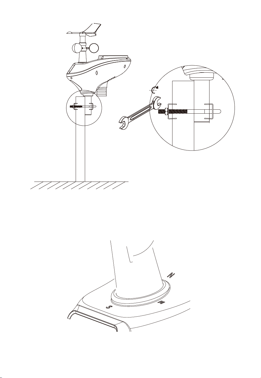
11
Figure 7
1. Reference Figure . Locate the four wind vane compass rose indicators
of N, E, S, W (representing North, East, South and West). Align the
compass rose direction upon final installation with a compass or GPS.
Figure 8
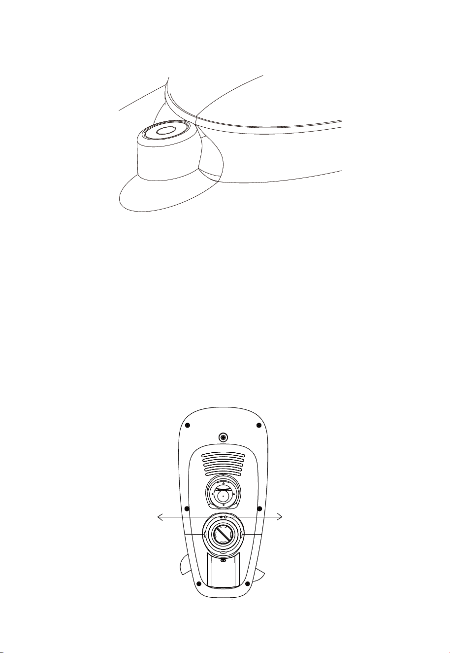
12
2. Reference Figure . Make sure the sensor array is completely level upon
final installation. Failure to do so will result in inaccurate rain gauge
readings.
Figure 9
5.3.5 Reset Button and Transmitter LED
In the event the sensor array is not transmitting, reset the sensor array.
With an open ended paperclip, press and hold the RESET BUTTON for three
seconds to completely discharge the voltage.
Take out the batteries and wait one minute, while covering the solar panel to
drain the voltage.
Put batteries back in and resynchronize with console by powering down and up
the console with the sensor array about 10 feet away.
Figure 10
LED RESET BUTTON
LED RESET BUTTON
13
5.4 Best Practices for Wireless Communication
Note: To insure proper communication, mount the remote sensor(s) upright
on a vertical surface, such as a wall. Do not lay the sensor flat.
Wireless communication is susceptible to interference, distance, walls and metal
barriers. We recommend the following best practices for trouble free wireless
communication.
1. Electro-Magnetic Interference (EMI). Keep the console several feet
away from computer monitors and TVs.
2. Radio Frequency Interference (RFI). If you have other 433 MHz
devices and communication is intermittent, try turning off these other
devices for troubleshooting purposes. You may need to relocate the
transmitters or receivers to avoid intermittent communication.
3. Line of Sight Rating. This device is rated at 300 feet line of sight (no
interference, barriers or walls) but typically you will get 100 feet
maximum under most real-world installations, which include passing
through barriers or walls.
4. Metal Barriers. Radio frequency will not pass through metal barriers
such as aluminum siding. If you have metal siding, align the remote and
console through a window to get a clear line of sight.
The following is a table of reception loss vs. the transmission medium. Each
“wall” or obstruction decreases the transmission range by the factor shown
below.
Medium
RF Signal Strength Reduction
Glass (untreated)
5-15%
Plastics
10-15%
Wood
10-40%
Brick
10-40%
Concrete
40-80%
Metal
90-100%
14
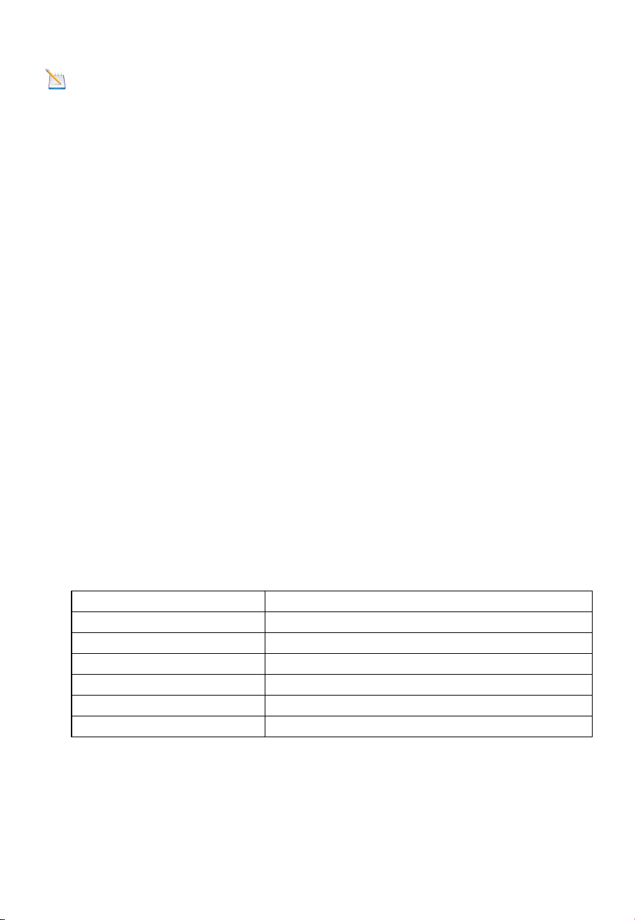
5.5 Display console
Figure 11
1. Insert the 5V AC adaptor into the back of the display console
Note: Place the outdoor sensor array about 5 to 10 feet from the display console
and wait several minutes for the remote sensors to synchronize with the display
console.
2. Insert 3 AAA batteries into the display console. Please insert the battery as
blew figure 12:
Figure 12
15
Note: The batteries are intended for back-up power only. The backlight will
remain on for 5 seconds when on back up battery power only. Only when
you use power adapter it will the back-light be continuously on.
3. Keep both sensor and the display console together for 15 minutes to lock in
the sensor signals.
4. (Optional)-Spin the wind cups to simulate wind speed. Take the sensor to the
sink and slowly drip water into the rain bucket to simulate rain.
5. After 15miuntes, follow the mounting instructions for proper placement of
sensors.
Note: Your display console should have readings in all sections. Wind and
Rain will show 0’s (connected) until wind or rian occur or are simulated.
Note: If you only use battery to power up display console, you must press
LIGHT/SNOOZE key to light up the LCD before press any other key.
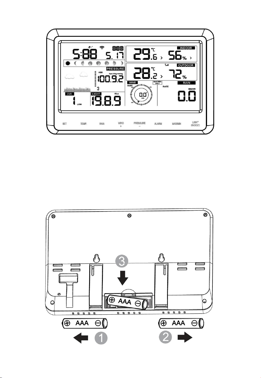
5.5.1 Vertical Desk Stand
The console is best viewed above from a 20 to 30 degree angle.
In addition to the fold out desk stand on the back of the display, console, the
console also includes a vertical desk stand to improve the viewing able on a
desk, as shown in Figure 13.
Figure 13
16
6. Display Console Operation
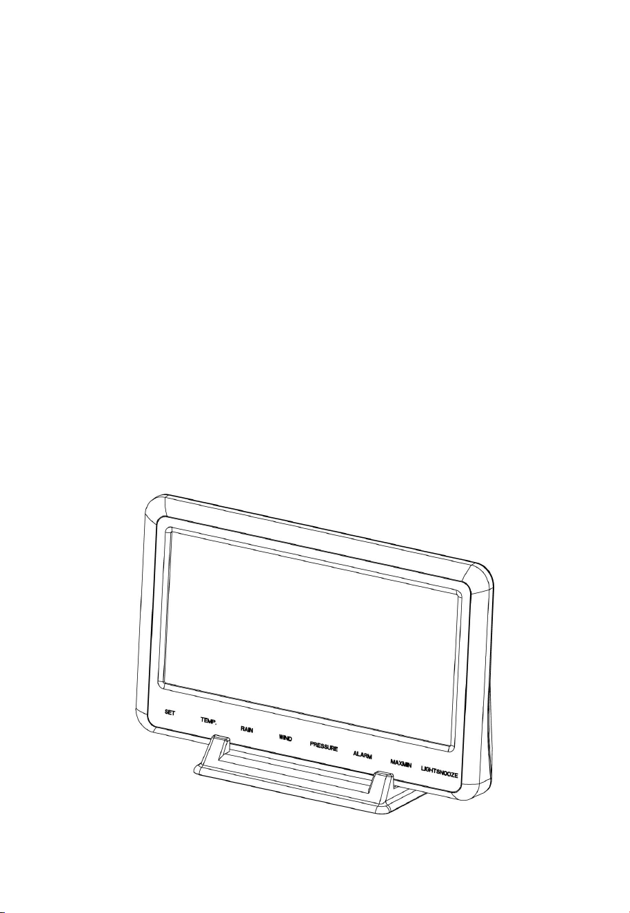
6.1 Screen Display
1.Time
10. Rain fall
2. Moon phase
11. Outdoor temperature
3. Barometric Pressure
12. Outdoor humidity
4. Weather forecast
13. RF icon
5. UV index
14. Indoor humidity
6. Light
15. Indoor temperature
7. Wind speed
16. Date
8. Wind direction
17. WIFI icon
9. MAX/MIN Daily
Figure 14
6.2 Initial Display Console Set Up
Note: The sensor array must be powered and updating before powering up the
console, or the console will timeout searching for the sensors. Perform this step
last.
Make certain the weather station sensor array is at least 3m from the console
and within 100m of the console. If the weather station is too close or too far away,
it will not receive a proper signal.
17
1.
Insert the power adapter into the power jack of the console, and plug in the
adapter. The LCD display will beep once and then light up. The unit will show
software version number 2 seconds after power reset.
Then the unit will turn on all segments of the LCD for 3 seconds, the unit will start
to register the outdoor channel for 3 minutes.
After initialization, the console will instantly display indoor temperature, humidity,
barometer, tendency, date and time. The wind speed, wind direction, rain, and
outdoor temperature and humidity will update on the display within a few minutes.
The remote search icon will turn on:
Do not touch any buttons until the remote sensor reports in, otherwise the
remote sensor search mode will be terminated and the search icon will turn off.
When the remote sensor data has been received, the console will automatically
switch to the normal mode, and all further settings can be performed.
If it does not update, please reference the troubleshooting guide in Section 11.
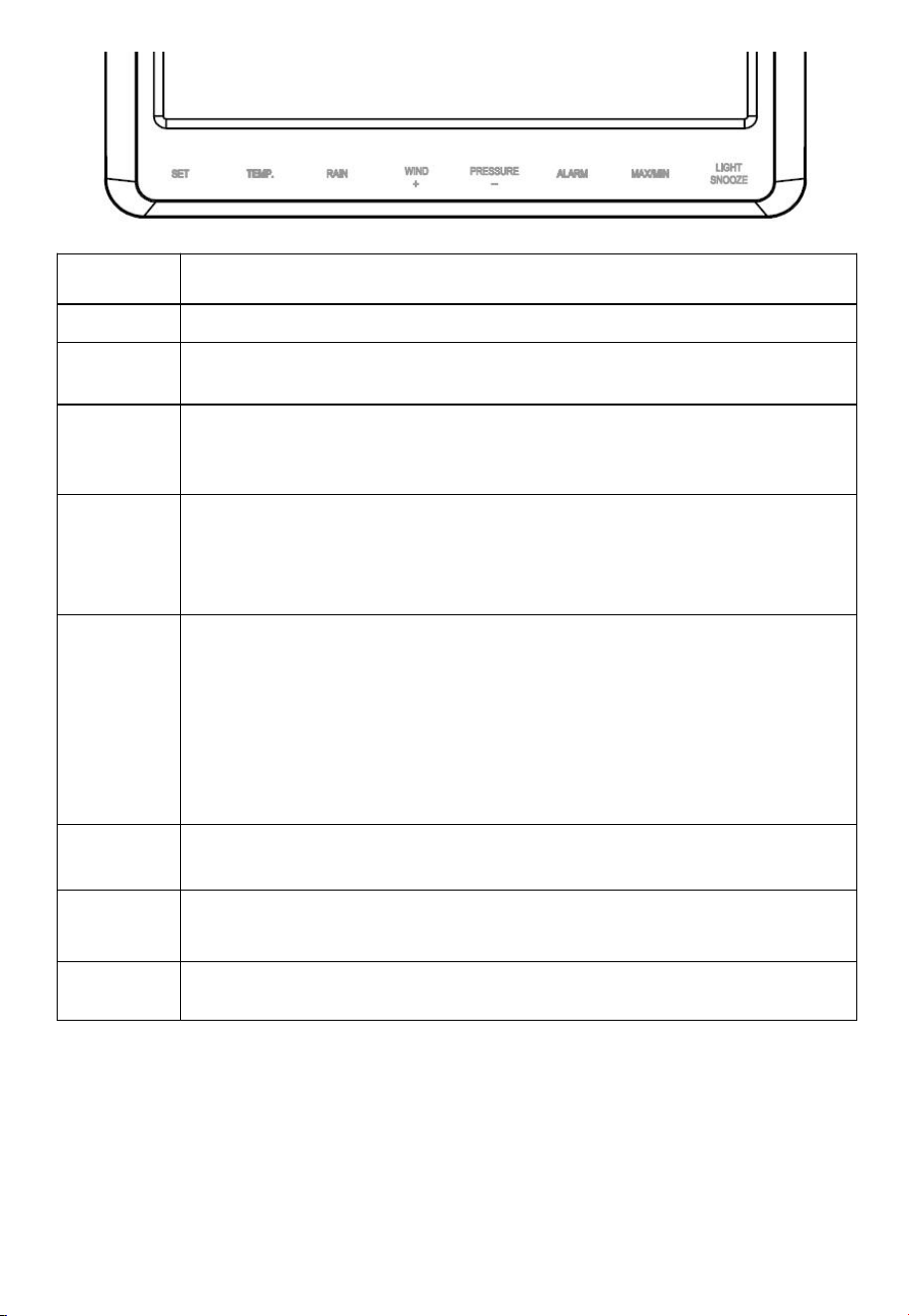
6.3 Key function
The console has eight keys for easy operation
18
Key
Description
SET
Hold this key to enter setting mode
TEMP.
Press this key to view wind Chill, Heat Index, Dew Point
Temperature
RAIN
Press this key to view Rain Rate, event, Rain Day, Rain Week,
Rain Month, and Rain total*
Press the RAIN key 2s to reset current display rain*
WIND/ +
Press this key to view wind/gust and wind direction
In Setting mode, pressing WIND/+ key select the unit or scrolls the
value; keeping press and holding WIND/+ key for 2 second will
increase/decrease digits in great steps.
PRESSU
RE/-
Press this key to view Absolute Pressure average of 12hr, 24hr,
48hr and 72hr
Press and hold 2s this key to view the absolute and relative
pressure
In Setting mode, pressing WIND/+ key select the unit or scrolls the
value; keeping press and holding WIND/+ key for 2 second will
increase/decrease digits in great steps.
ALARM
Press this key to view the alarm value of Temperature /
Humidity/rain rate/rain day/wind
MAX/MIN
Press this key to view the MAX/MIN value of Temperature /
Humidity/rain rate/rain day/wind/UVI/LIGHT/Absolute Pressure
LIGHT
/SNOOZE
Press this key to adjust LCD backlight brightness: HI/MID/OFF
Hold LIGHT/SNOOZE key to register new transmitter
Figure 15
*Rainfall Readings
Press RAIN key to view rain history:
Rain rate: it forecast the rain per hour base on the recently 10 minute’s
rainfall. For example: the rainfall of recent 10 minutes is 12mm, the
rain/hour is 12mm*6=72mm/h.
Rain event: It start to record the rain event value form the rain falls, the rain
19
event is over and value reset to 0 if last 24 hour rainfall less 1mm and the
last 1 hour no rainfall.
Day: 24 hr period from 0:00 - 24:00.
Week: defined by calendar week i.e. Sunday – Saturday.
Month: defined by calendar Month i.e. January 1 - January 31.
Total: running total since station was powered up
*Reset Rainfall History:
Reset week rain, will auto reset day rain
Reset month rain, will auto reset week and day rain.
Reset total rain, will auto reset month, week and day rain.
Note:
1) When power on, press WIND/+ and PRESSURE /- key to reset the weather
station and clear all records memory, and clears all user settings to default.
2) When power on, press TEMP. key to skip receive RF signal.
3) The setting procedure can be exited at any time by either pressing the
LIGHT /SNOOZE key or waiting for the 30-second time-out to take effect.
6.4 Set mode
The Set Mode allows you to change date, time, units of measure and other
important functions, as referenced in Figure 16.
To enter the Set Mode, press and hold the SET key for two seconds (SET + 2
seconds). To advance each command, press (do not hold) the SET key.
Command
Function
Description
Settings
SET + 2
seconds
BEEP
Turns on or off the
beep with each
keystroke
Press WIND/+ or PRSSURE/-
to toggle OFF and ON
SET
RST
Reset max/min daily
at 12:00am (on) or
manually (off)
Press WIND/+ or PRSSURE/-
to toggle OFF and ON
SET
24H
12/24 Hour Format
Press WIND/+ or PRSSURE/-
to toggle between 12 hour
(12h) and 24 hour (24h)
format
SET
HR
Hour of Day
Press WIND/+ to increase.
PRSSURE/- to decrease
20
Figure 16
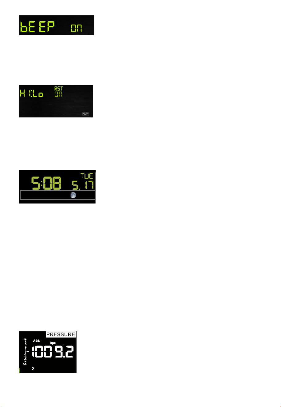
6.4.1 BEEP:
SET
MIN
Minute of Day
Press WIND/+ to increase.
PRSSURE/- to decrease
SET
M-D
Month Day Format
Press WIND/+ or PRSSURE/-
to toggle between M-D
(month/day) format and D-M
(day/month) format
SET
Y
Year
Press WIND/+ to increase
and PRSSURE/- to decrease
SET
M
Month of Year
Press WIND/+ to increase
and PRSSURE/- to decrease
SET
D
Day of Month
Press WIND/+ to increase
and PRSSURE/- to decrease
SET
hPa
Barometric Pressure
Units of Measure
Press WIND/+ to toggle
between inHg,mmhg and hPa
SET
PRESSU
RE REL
Relative Pressure
Calibration
Press WIND/+ to increase.
PRSSURE/- to decrease. For
details on relative barometric
pressure calibration,
reference Section 6.4.6.
SET
W/M
2
Light units of
Measure
Press WIND/+ to toggle
between klux, kfc, and W/M
2
SET
°C
Temperature Units
of Measure
Press WIND/+ to toggle
between °F and °C
SET
Km/h
Wind speed units of
Measure
Press WIND/+ to toggle
between km/h, mph, knots,
m/s and bft
SET
Mm
Rainfall units of
Measure
Press WIND/+ to toggle
between mm and inch
SET
NTH
Northern
Hemisphere (NTH)
or southern
Hemisphere (STH)
select
Press WIND/+ to toggle
between Northern and
southern Hemisphere
SET
Exit Set Mode
21
- Press the SET key for 2 seconds to select the beep section, ON/OFF section
digits will start flashing, press the WIND/+ or PRSSURE/- key to select ON or
OFF.
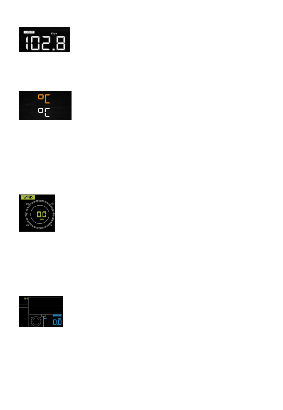
6.4.2 MAX/MIN Daily:
- Press the SET key twice to select the MAX/MIN Daily section, ON/OFF section
digits will start flashing. Press the WIND/+ or PRSSURE/- key to select ON or
OFF . (Default ON. ON: Reset max/min daily at 12:00am).
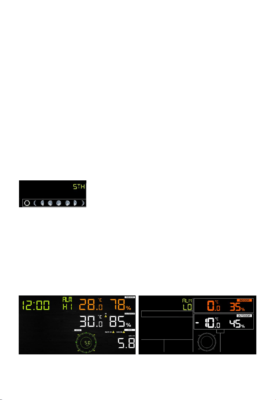
6.4.3 Time / Date
- Press the SET key third time to select the 12/24 hour format section (default:
24hr).
- Press the SET key fourth time to select the hour section.
- Press the SET key fifth time to select the minutes section.
- Press the SET key sixth time to select DD-MM or MM-DD format. (Default
DD-MM format)
- Press the SET key seventh time to select year.
- Press the SET key eighth time to select month.
- Press the SET key ninth time to select day.
Note: Press the WIND/+ or PRSSURE/- key to set the value.
Note: If user to change minute value, second will auto clear to 0.
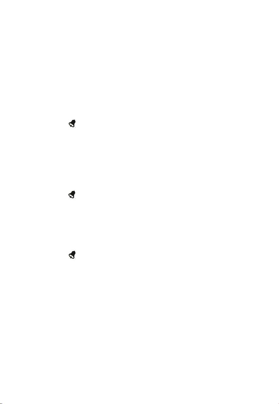
6.4.4 Pressure
1) Viewing Absolute vs. Relative Pressure

22
To switch between absolute and relative pressure, press and hold the
[PRESSURE -] button for two seconds.
Absolute pressure is the measured atmospheric pressure, and is a function of
altitude, and to a lesser extent, changes in weather conditions.
Absolute pressure is not corrected to sea-level conditions.
Relative pressure is corrected to sea-level conditions.
2) Rate of Change of Pressure Graph
The rate of change of pressure graphic is shown to the left of the barometric
pressure and signifies the difference between the daily average pressure and
the 30 day average (in hPa).
3) Viewing Pressure History
Press the [PRESSURE -] button to view the 12 hour, 24 hour, 48 hour and 72
hour pressure average.
4) Relative Pressure Calibration Discussion
To compare pressure conditions from one location to another, meteorologists
correct pressure to sea-level conditions. Because the air pressure decreases as
you rise in altitude, the sea-level corrected pressure (the pressure your location
would be at if located at sea-level) is generally higher than your measured
pressure.
Thus, your absolute pressure may read 28.62 inHg (969 mb) at an altitude of
1000 feet (305 m), but the relative pressure is 30.00 inHg (1016 mb).
The standard sea-level pressure is 29.92 inHg (1013 mb). This is the average
sea-level pressure around the world. Relative pressure measurements greater
than 29.92 inHg (1013 mb) are considered high pressure and relative pressure
measurements less than 29.92 inHg are considered low pressure.
To determine the relative pressure for your location, locate an official reporting
station near you (the internet is the best source for real time barometer
conditions, such as Weather.com or Wunderground.com), and set your weather
station to match the official reporting station.
23
6.4.5 Light
- Press the SET key 12th to select light unit (Klux, kfc, w/m2; default: w/m2).
6.4.6 Temperature
- Press the SET key 13th to select in/outdoor temperature unit (C or F; default:
C).
- In normal model, press the TEMP. key to view wind Chill, Heat Index, Dew
Point Temperature. Press the TEMP. key for 5 second, will register new
transmitter.
6.4.7 Wind speed
- Press the SET key 14th to select wind speed unit ( km/h, mph, knots, m/s, bft;
default: km/h ).
- In normal mode, press and release the WIND/+ key to view the wind, gust and
wind direction.
6.4.8 Rain
- Press the SET key 15th to select rainfall unit ( in or mm; default: mm).
- In normal mode, press and release the RAIN key to view rain of rate, event, day,
week, month and total.
- Press the RAIN key for 2 seconds to reset current display rain.
*Rainfall Readings
24
Rain rate: it forecast the rain per hour base on the recently 10 minute’s
rainfall. For example: the rainfall of recent 10 minutes is 12mm, the
rain/hour is 12mm*6=72mm/h.
Rain event: It start to record the rain event value form the rain falls, the rain
event is over and value reset to 0 if last 24 hour rainfall less 10mm and the
last 1 hour no rainfall.
Day: 24 hr period from 0:00 - 24:00.
Week: defined by calendar week i.e. Sunday – Saturday.
Month: defined by calendar Month i.e. January 1 - January 31.
Total: running total since station was powered up
*Reset Rainfall History:
Reset week rain, will auto reset day rain
Reset month rain, will auto reset week and day rain.
Reset total rain, will auto reset month, week and day rain.
6.4.9 Moon phase
- Press the SET key 16th to Northern or Southern Hemisphere select.
6.5
Alarm mode
6.5.1 View Alarm value
Press and release ALARM key to display high alarm,Press ALARM key again
to display low alarm. Press ALARM key third time or press LIGHT /SNOOZE key
return to normal mode.
In alarm mode:
- Press RAIN key to shift display rain rate or day rain alarm data.
25
- Press WIND/+key to shift display wind or gust alarm data.
6.5.2 Alarm setting mode:
Hold the ALARM key for 2 seconds to enter alarm setting mode:
1. Time of Day Alarm. The hour will begin flashing. Press the WIND/+ or
PRESSURE/- key to change the hour value. Press the SET key to set the
minute value. The minute will begin flashing. Press the WIND/+ or
PRESSURE/- key to increase or decrease the minute value.
2.
Press the ALARM key to turn the alarm on or off (if the alarm is enabled, the
alarm icon will be turned on).
3. Indoor Temperature High Alarm. Press the SET key to set the indoor
temperature high alarm. The indoor temperature will begin flashing. Press
the WIND/+ or PRESSURE/- key to change the indoor temperature alarm
value.
4. Press the ALARM key to turn the alarm on or off (if the alarm is enabled, the
alarm icon will be turned on).
5. Indoor Temperature Low Alarm. Press the SET key to set the indoor
temperature low alarm. The indoor temperature will begin flashing. Press
the WIND/+ or PRESSURE/- key to change the indoor temperature alarm
value.
6. Press the ALARM key to turn the alarm on or off (if the alarm is enabled, the
alarm icon will be turned on).
7. Indoor Humidity High Alarm.
8. Indoor Humidity Low Alarm.
9. Outdoor Temperature High Alarm.
10. Outdoor Temperature Low Alarm.
11. Outdoor Humidity High Alarm.
12. Outdoor Humidity Low Alarm
13. Wind High Alarm
14. Wing gust High Alarm
15. Rain rate high Alarm
16. Rain day high Alarm
17. Press the WIND/+ or PRESSURE/- to adjust alarm values.
18. Press the SET key to confirm & move to the next item.
19. Press the ALARM key to on/off the alarm
26
Note: when alert is triggered, the current triggering source icon for time,
icon for high value and icon for low value will be flashing, indicating
alert is triggered.
Note: press ALARM key third time back to normal mode or press LIGHT
/SNOOZE key back to normal mode.
When a weather alarm condition has been triggered, the alarm will sound for 120
seconds and the corresponding icon will flash until the weather condition is no
longer present. Press any key to mute the alarm.
You can also set a time of day alarm using the same method.
6.5.3 Alarm Setting Order:
1. Time alarm setting
2. Indoor high temperature setting
3. Indoor low temperature setting
4. Indoor high humidity setting
5. Indoor low humidity setting
6. Outdoor high temperature setting
7. Outdoor low temperature setting
8. Outdoor high humidity setting
9. Outdoor low humidity setting
10. High wind setting
11. High gust setting
12. Rain rate high setting
13. Rain day high setting
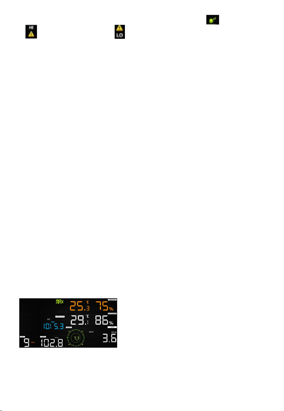
6.6 Max/min mode
6.6.1 Press and release MAX/MIN key to display MAX data
- Press TEMP. key to view wind chill, heat index and dew point max.
- Press RAIN key to view rain rate, rain day, rain week and rain month max.
- Press WIND/+ to view wind and gust max.
- Press PRESSURE/- to hold 2 seconds to view pressure absolute and relative
27
max.
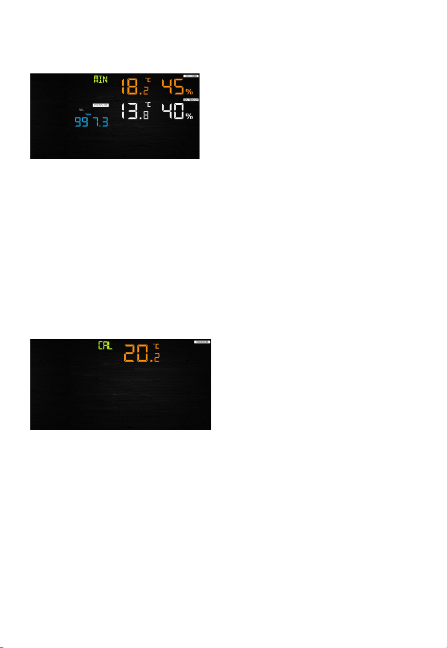
6.6.2 Press again to display min data
- Press TEMP. key to view wind chill and dew point min.
- Press PRESSURE/-to hold 2 seconds to view pressure absolute and relative
min.
Note: press and hold 2s MAX/MIN button to reset all max or min.
press MAX/MIN key third time back to normal mode or press LIGHT
/SNOOZE key back to normal mode.
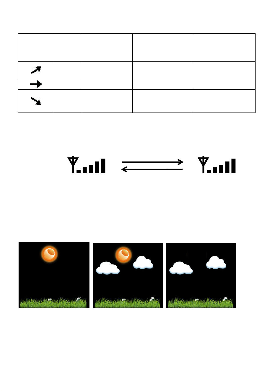
6.7 Calibration mode
Hold the TEMP. and MAX/MIN key together for 5 seconds to enter calibration
mode.
- Press the WIND/+and PRESSURE/- key to adjust values.
- Press the SET key to confirm & move to the next item.
- Press the ALARM key to reset any adjusted value.
- Press the LIGHT /SNOOZE key at any time to exit.
6.7.1 Calibration Order:
1. Indoor temperature offset calibrated (range +/-5˚C, default: 0 degrees)
2. Indoor humidity offset calibrated (range +/-10%)
3. Outdoor temperature offset calibrated (range +/-5˚C, default: 0 degrees)
4. Outdoor humidity offset calibrated (range +/-10%)
5. Absolute pressure offset calibrated (range +/-50hpa)

28
6. Wind direction offset calibrated (adjust by degree)
7. Wind speed factor adjust, default 100% (range 50% to 150%)
8. Rain factor adjust, default 100% (range 50% to 150%)
6.8 Other Features
6.8.1 Factory Reset/Clear Memory
To restore the console to factory default, perform the following steps:
1. Remove the power from the console by removing the batteries and
disconnecting the AC adapter.
2. Apply power by connecting the AC adapter.
3. Wait for all of the segments to appear on the screen,.
4. Press and hold the WIND/+ and PRESSURE/- keys at the same time until
the console power up sequence is complete (about 5 seconds).
5. Replace the batteries.
6.8.2 Register New Transmitter
Press and hold the LIGHT /SNOOZE button for 5 seconds, and the console will
re-register the wireless sensor.
6.8.3 Backlight (constant backlight requires operation with AC adapter.)
1) With AC adaptor.
The backlight can only be continuously on when the AC adapter is permanently
on. When the AC adapter is disconnected, the backlight can be temporarily
turned on.
Press the LIGHT SNOOZE key to adjust the brightness between High, Low and
Off.
2) Without AC adaptor
To reduce power consumption, the display console will automatically enter sleep
mode and will not send data to the Internet if no key is pressed for 15s. Hold the
LIGHT /SNOOZE key in sleep mode or plug in the DC adapter wake up
equipment.
6.8.4 Tendency indicators
Tendency arrows allow you to quickly determine of temperature or pressure are
rising and falling in a three hour update period, updated every 30 minutes.
Eg. : At 3:00 - compare to 12:00 data; at 3:30 -compare to 12:30 ….. etc
29
6.8.5 Wireless Signal Strength Indicator
The wireless signal strength displ ays reception quality. If no signal is lost, the
signal str ength indicator will display 5 bars. If the signal is lost once, four bars will
be displ ayed.
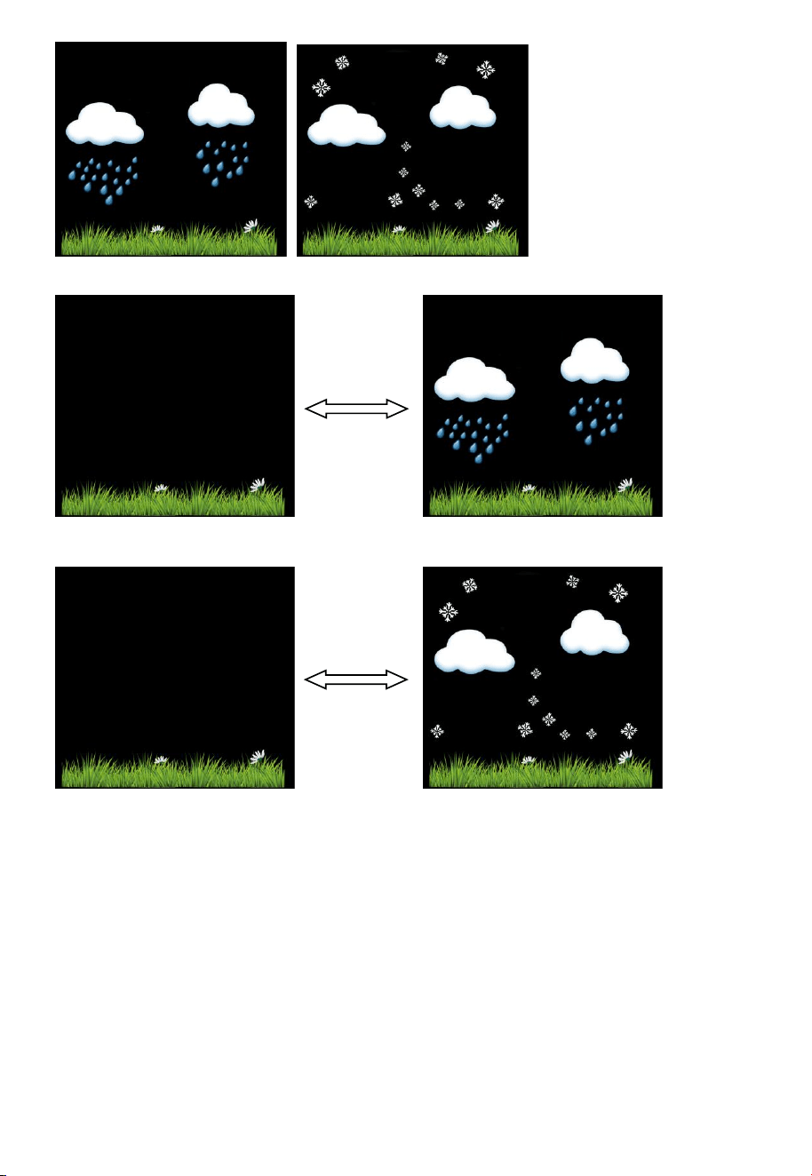
6.8.6 Weather forecast
There are six color forecas t icons use changing atmospheric pressure to predict
weathers conditions for the next 6-hours . Please allow at least one month for the
weather station to learn the barometric pressure over time.
Sunny Partly sunny Cloudy
Tendency
indicators
Humidity Temperature Pressure
Rising Rising > 3%
Rising >=
1C/2F
Rising > 1hpa
Steady
Change <= 3%
Change < 1C/2F
Change <= 1hpa
Falling Falling > 3% Falling >= 1C/2F Falling > 1hpa
Lost the signal
once
Received t he signal once
30
Rainy Snowy
Storm rainy
Storm Snowy
Note: Snowy icon will appear in place of rainy icon when the outdoor
temperature is below 32 F (0˚C).
Weather Forecasting Description and Limitations
In general, if the rate of change of pressure increases, the weather is generally
improving (sunny to partly cloudy). If the rate of change of pressure decreases,
the weather is generally degrading (cloudy, rainy or stormy). If the rate of change
is relatively steady, it will read partly cloudy.
The reason the current conditions do not match the forecast icon is because the
forecast is a prediction 24-48 hours in advance. In most locations, this prediction

31
is only 70% accurate and it is a good idea to consult the N ational Weather
Service for more accurate weather forecasts. In some locations, this prediction
may be less or more accurate. However, it is still an interesting educational tool
for learning why the weather changes.
The National Weather Service (and other weather services such as Accuweather
and The Weather Channel) have many tools at their disposal to predict weather
conditions, including weather r adar, weather models, and detailed mappin g of
ground conditions.
6.8.7 Snooze
When time alarm has been triggered, the alarm will sound and alar m icon flash
for 120 s. Press SNOOZE/LIGHT key to silence the ala rm for 10 minutes and
then the alarm will sound again when that time is up. Press any key except
SNOOZE/LIGHT key to stop the ala rm.
7. Specification:
Outdoor data
Transmission distance in open field
: 100m(330 feet)
Frequency
: 433MHz/868MHz/915MHz
Temperature range
: -40˚C--60˚C
Accuracy
: + / - 1 °C
Resolution
: 0.1˚C
Measuring range rel. humidity
: 10%
~
99%
Accuracy
: +/- 5%
Rain volume display
: 0 – 6000mm (show --- if outside range)
Accuracy
: +/- 10%
Wind speed
: 0-50m/s (0~100mph)
(show --- if outside range)
Accuracy
: +/- 1m/s (wind speed< 5m/s)
+/-10% (wind speed > 5m/s)
Light
: 0-200k Lux
Accuracy
: +/- 15%
Measuring interval thermo-hygro
sensor
: 16sec
32
Indoor data
Indoor t emperature range
: -10˚C--60˚C (14℉ to + 140℉)
(show --- if ou tside range)
Resolution
: 0.1˚C
Measuring range rel. Humidity
: 10%
~
99%
Resolution
: 1%
Measuring range air pressure
: 700-1100hpa (20.67inHg – 32.5inHg)
Accuracy
: +/-3hpa
Resolution
: 0.1hpa (0.01inHg)
Alarm duration
: 120 sec
Power co nsumption
Base station: 5V DC adaptor (included), Power Consumption: 0.5 Watts
(1.25 Watts during WiFi configuration mode)
Base station: 3 x AAA batteries (not included)
Remote sensor: 3 x AA batteries (not incl uded), The primary power source
is the solar panel. The batteries provide backup power when there is limited
solar energy
8. Live Internet Publishing
This weather station sends data to three free hosting services:
Hosting
Service
Website Description
Weather
Undergound
WeatherUndeground.com
Weather Underground is a free
weather hosting ser vice that
allows you to send and view your
weather station data real-time,
view graphs and gauges, import
text data for more detail ed
analysis and use iPhone, iPad
and Android applications
available at Wunderground.com.
Weather Underground is a
subsidiary of The Weather
Channel and IBM.

33
WeatherBug
Community
backyard.weatherbug.com
WeatherBug Community is an
extension of the WeatherBug
community of weather stations.
WeatherBug is a brand owned by
Earth Networks that provides live
weather data and maintains a
mesoscale network of over 8,000
weather stations.
Weather
Cloud
WeatherCloud.net
Weathercloud is a real-time
weather social network formed by
observers from around the world.
This weather station sends data to the Internet using your WiFi connection.
8.1 Connecting the Weather Station Console to WiFi
The WiFi feature only works when plugged into AC power due to higher energy
requirements.
To connect the weather station to WiFi, you must first download the application
from one of the following choices:
Apple App Store
Google Play Store
1) From your mobile device, visit the Apple App Store or Google Play Store
and search for the “WS Tool” application. Download this application to your
mobile device.
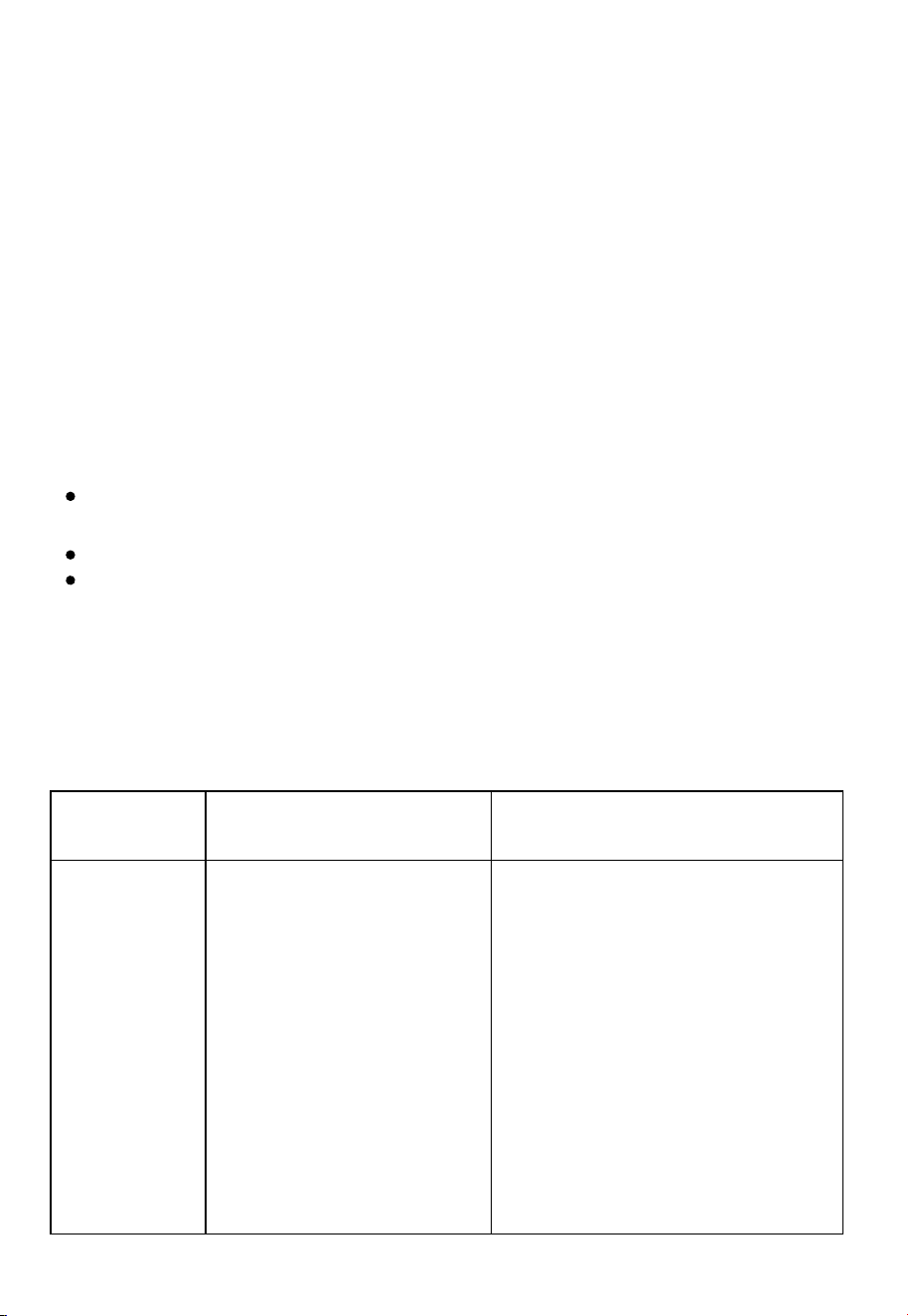
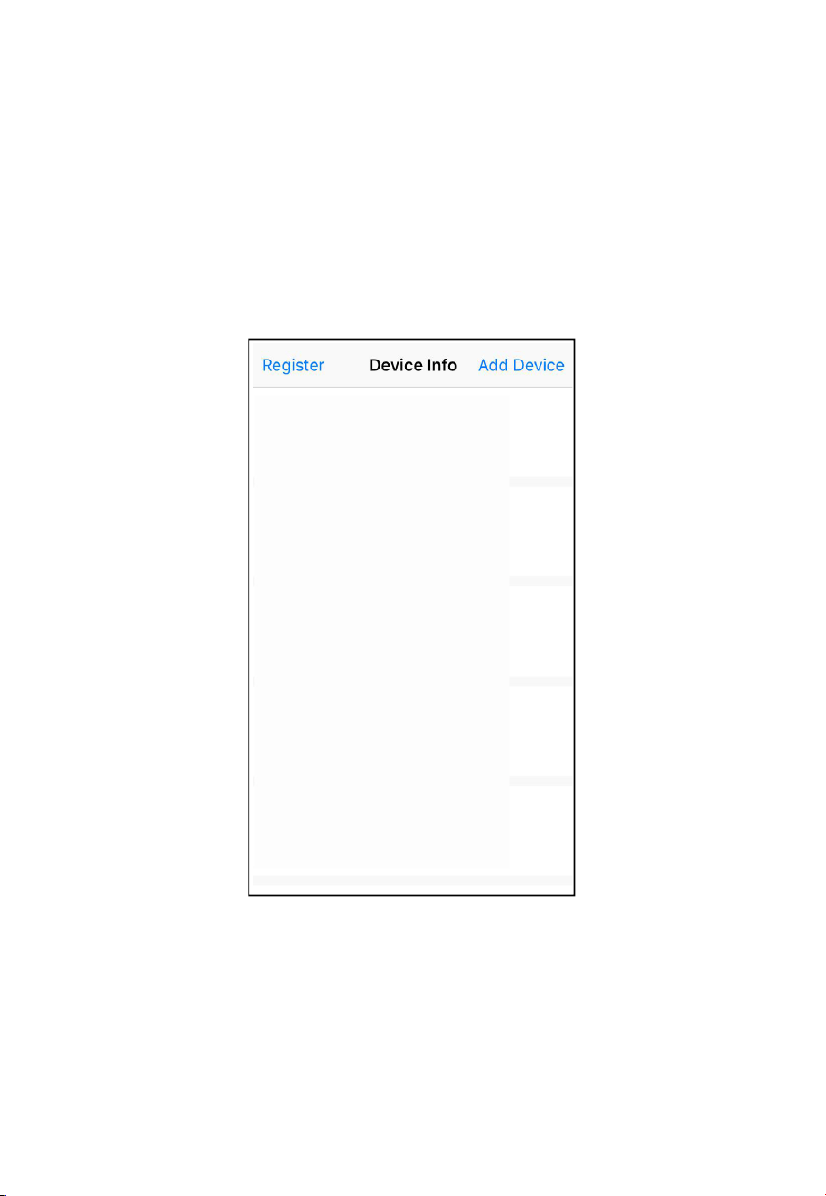
2) Run the WS Tool application, and select Add Device, as shown in below
figure.
34
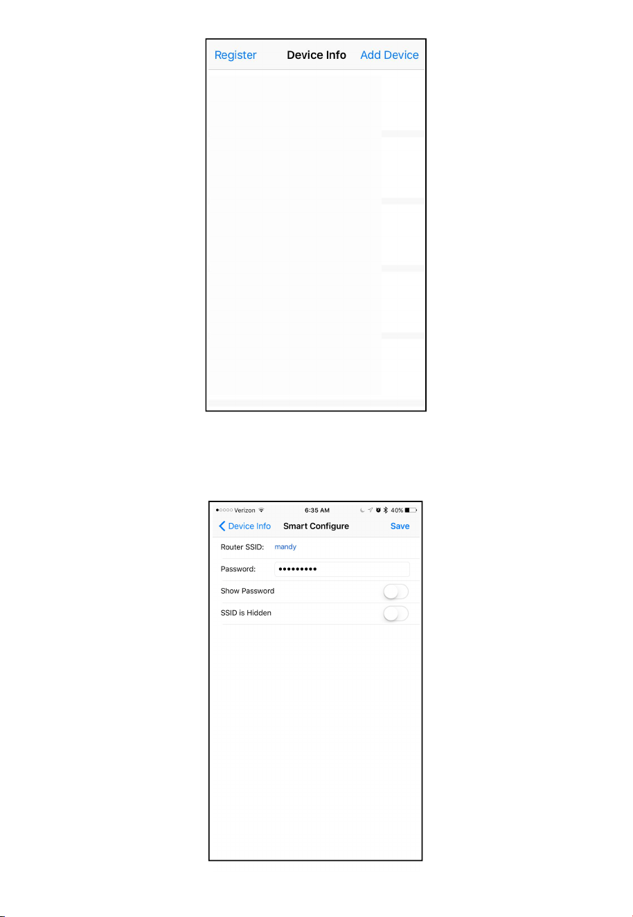
1. Make sure your mobile device is connected to your WiFi network.
Enter the password for your router, and select Save, as shown in below
figure.
35
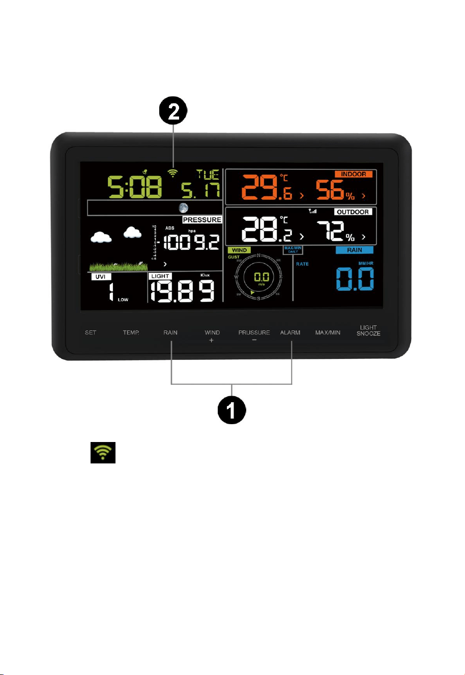
2. If the WiFi icon is not flashing rapidly, (1) press and hold the RAIN and
ALARM buttons at the same time for four seconds. (2) The WiFi icon will
begin flashing rapidly, indicating the console is searching for your WiFi
network.
Wi-Fi icon:
1) Not connected routers, don't show;
2) No network connection router, slow flash;
3) Connect the router with network, long bright;
4) Smart configure mode, fast flash.
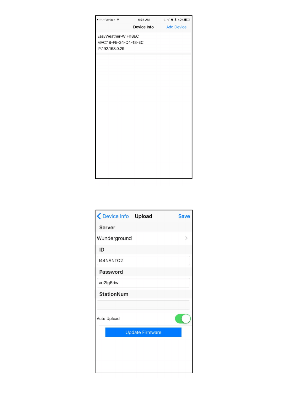
3. Once the console has connected to your WiFi network, the devices Mac
address and IP address will be displayed, as shown in below figure.
36
4. Register Enter your Wunderground.com and WeatherCloud.net Station
ID, Password and StationNum (see Section 9)
37
Now your weather statio n is connected for weather s erver. Down load WU app to
check your weather station records.
9. Registering with WeatherUnderground.com,
WeatherBug.com and WeatherCloud.net
9.1 WeatherUnderground.com
9.1.1 Register through WS TOOL
Run the WS Tool application, and select Register, as shown in below figure
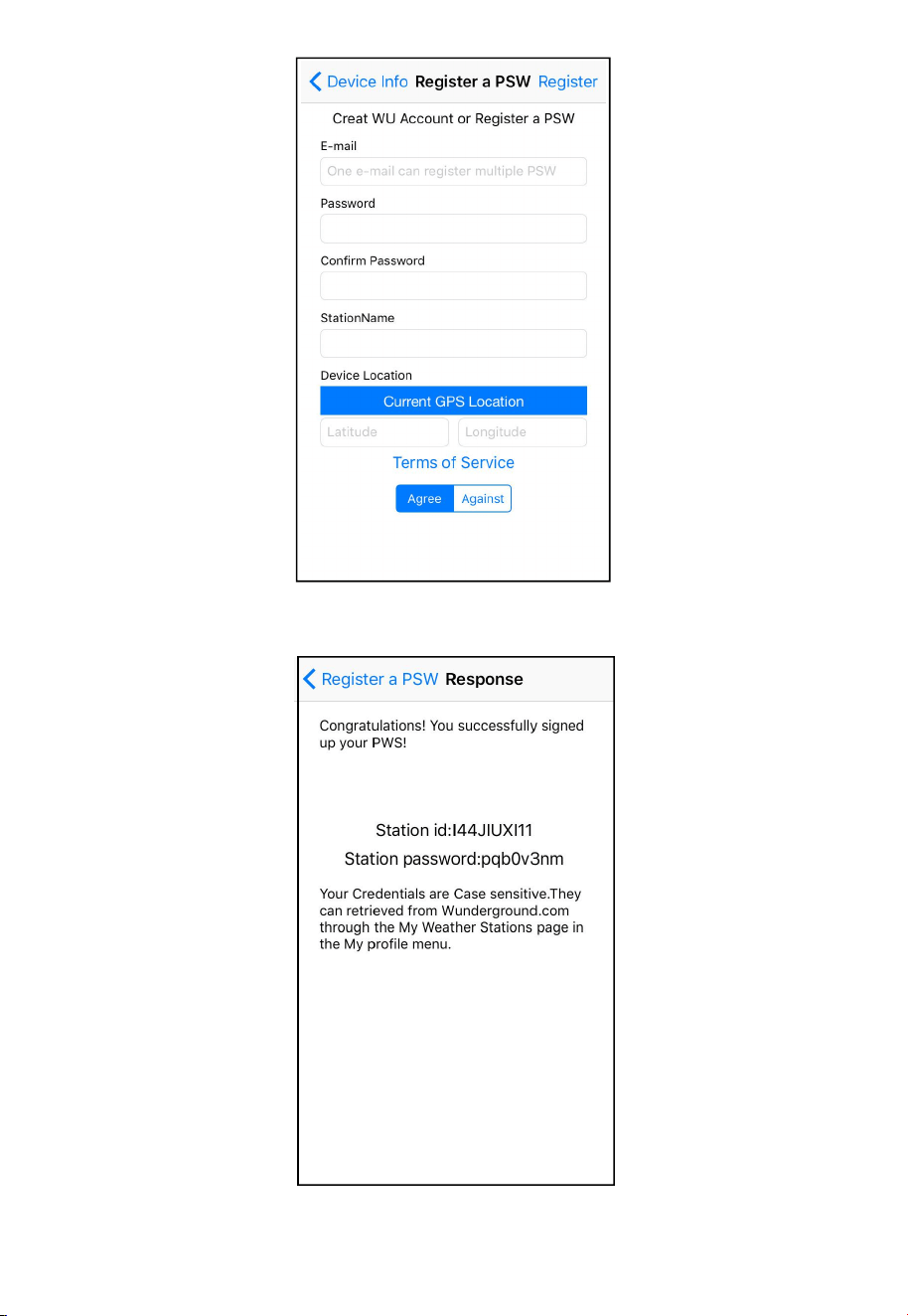
38
Fill the information and select Register. If register successfully, the Station ID
and Password will shown in below figure.
Make a note of the Station ID and Password, Enter the Station ID, Password and
39
Station Number (StationNum) into the WS Tool.
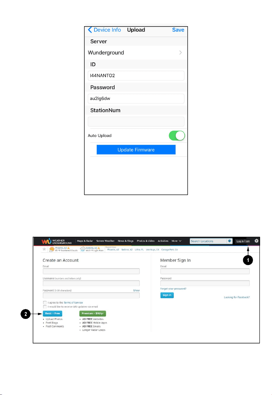
9.1.2 Register through WU website
Visit Wunderground.com and select the Join link at the top of the page. Select
the Free sign up option.
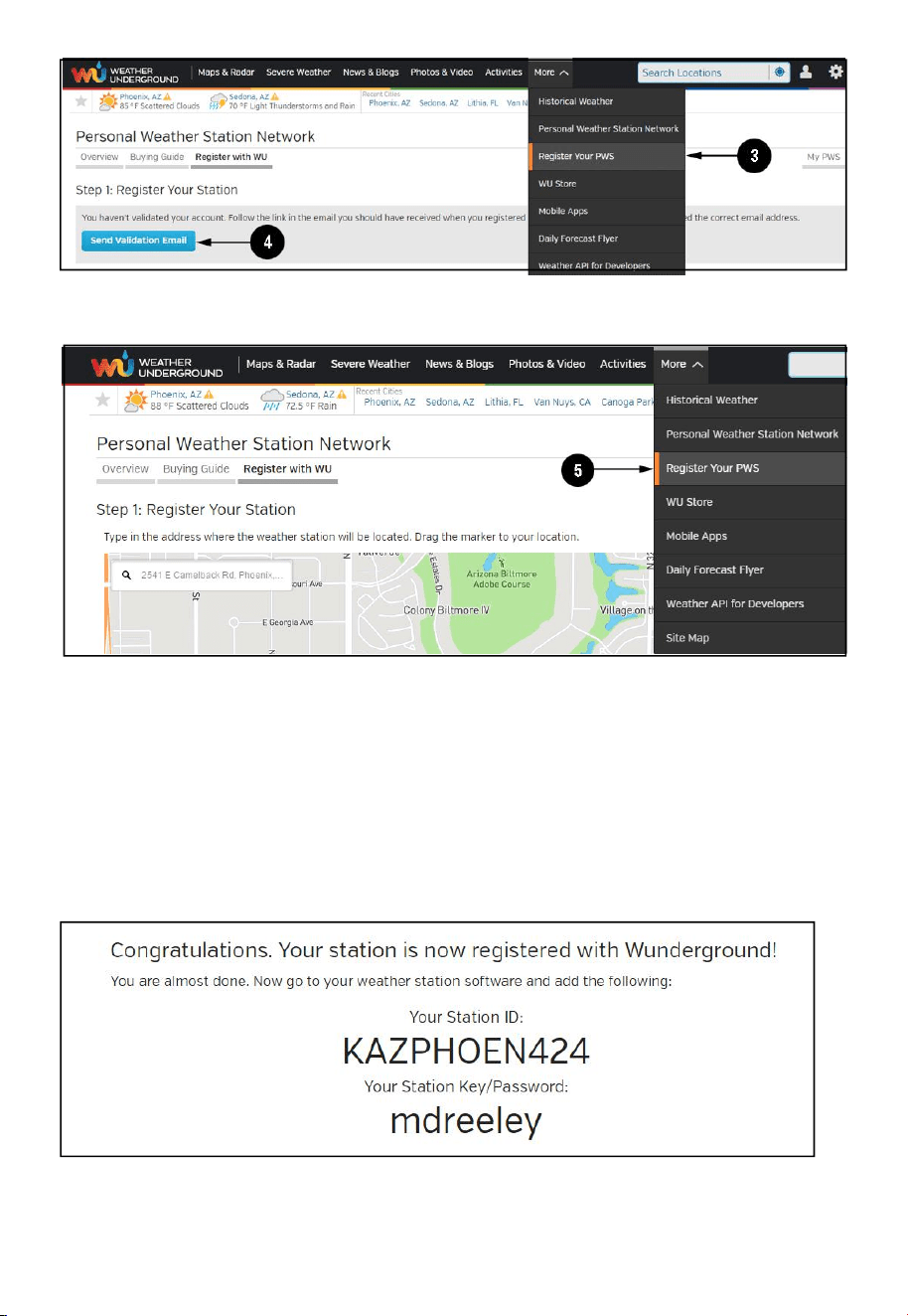
1. Select More | Register Your PWS.
2. Click Send Validation Email. Respond to the validation email from
Wunderground (it may take a few minutes).
40
3. Select More | Register Your PWS again and enter all of the information
requested.
4. After registering your station, make a note of the following:
Station ID
Station Key / Password
Enter the Station ID (ID), Station Key (Password) and Station Number
(StationNum) into the WS Tool.
Below figure is an example, and your station ID and password will be different.
Note: Your station ID will have the form: KSSCCCC###, where K is for USA
station (I for international), SS is your state, CCCC is your city and ### is the
41
station number in that city.
In the example above, KAZPHOEN424 is in the USA (K), State of Arizona (AZ),
City of Phoenix (PHOEN) and #424.
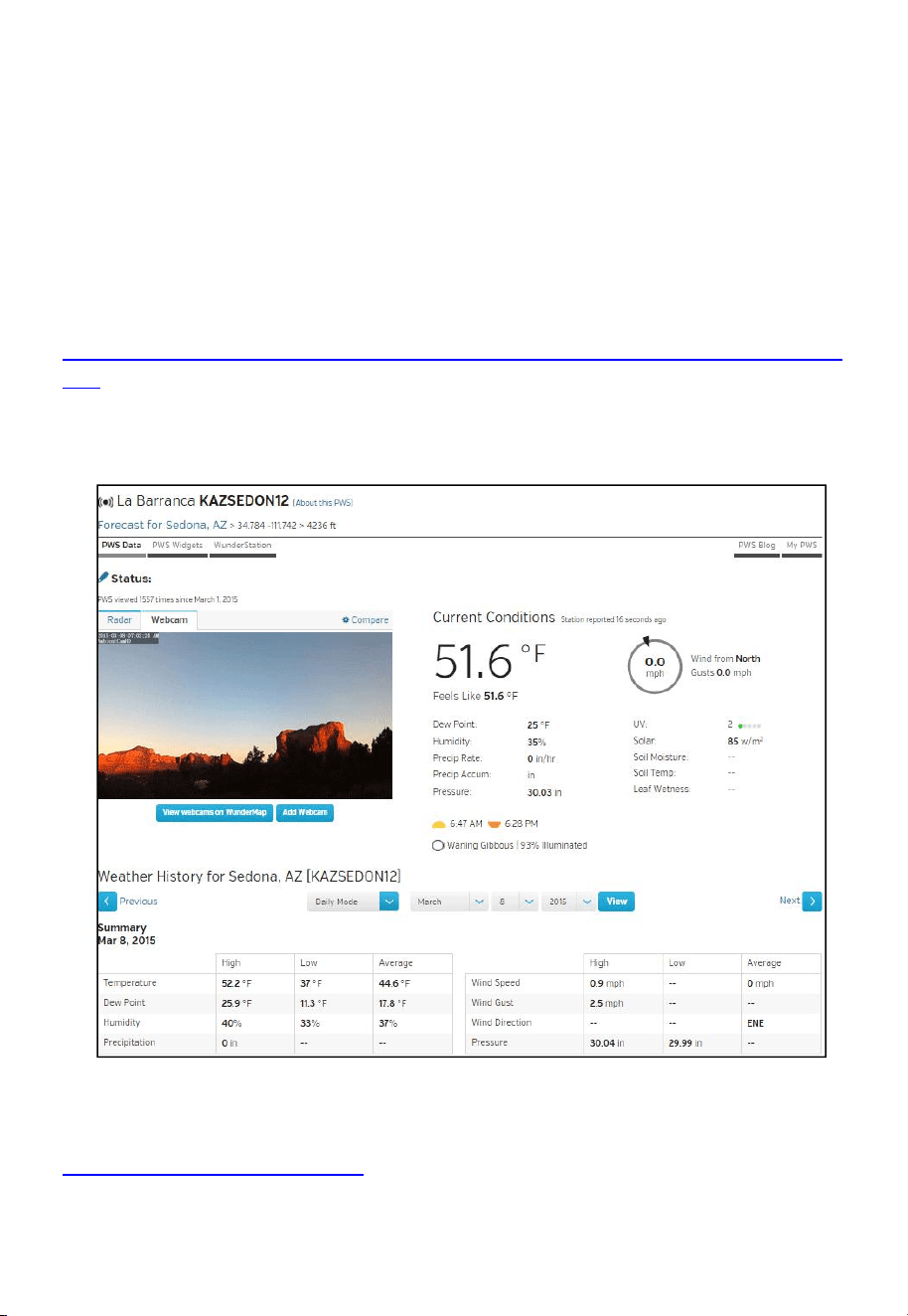
Viewing your Data on Wunderground.com
There are several ways to view your data on Wunderground:
Web Browser
Visit:
http://www.wunderground.com/personal-weather-station/dashboard?ID=STATIO
NID
where STATIONID is your personal station ID (example, KAZSEDON12).
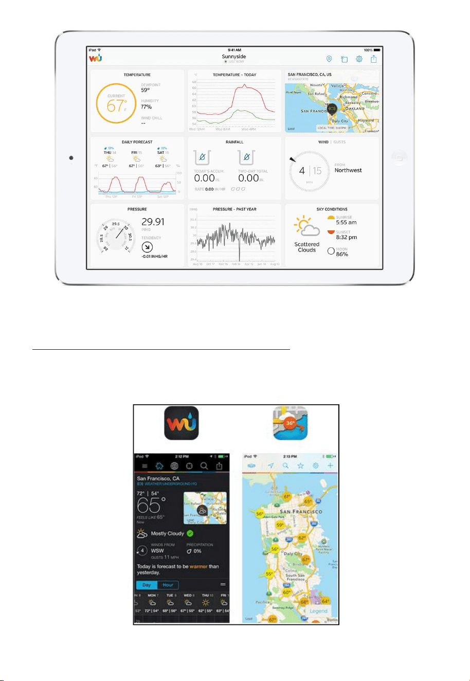
WunderStation iPad App
Visit:
http://www.WunderStation.com
to download the WunderStation iPad app.
43
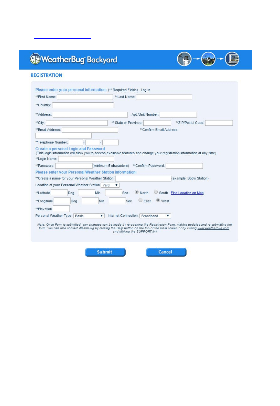
9.2 WeatherBug.com
Visit http://pws.ensb.us/ and Click here to register your station.
After registering your station, make a note of the following:
UserName
Password
Your Publisher ID
Your Station Number
Enter the Publisher ID (ID), Password and Station Number (StationNum) into the
Ambient Tool.
9.3 WeatherCloud
1. Visit WeatherCloud.net and enter a Username, Email and Password.
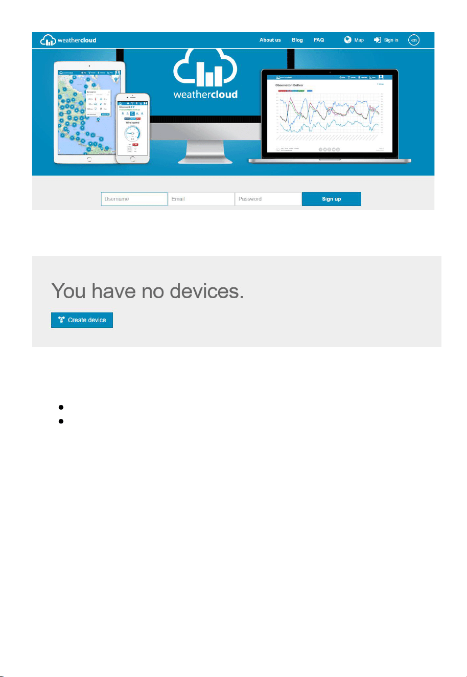
44
2. Respond to the validation email from WeatherCloud (it may take a few
minutes).
3. Select Create Device and enter your weather station information. Af ter
registering your station, make a note of the following:
Weathercloud ID
Key
Enter the Weathercloud ID (ID), Key (password) into the Ambient Tool. Leave
the Station Number (StationNum) blank.
10. Maintenance
1. Clean the rain gauge once every 3 months as follows.
Step 1: Make a note of the current rain totals by referencing the
calibration screen (reference Section 6.7 ). You will need to re-enter
these values after the calibratio n procedure it complete.
Step 2: Pour water into the rain collector to moisturize the dirt inside rain
bucket.
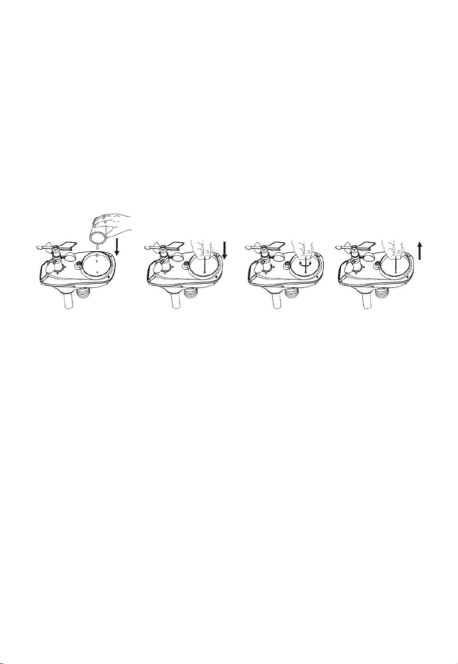
45
Step 3: Use an approximately 3 inch (80 mm) long cotton swab, and
push the cotton tip through the rain collector hole until is reaches the self
emptying mechanism, and press until the mechanism no longer rotates.
Step 4: Rotate the cotton swab back and forth, removing dirt from the
tipping mechanism and rain collector hole.
Step 5: Remove the cotton swab and flush with water to remove any
remaining dirt.
Step 6: Re-enter the rain totals recorded in Step 1.
2. Clean the solar radiation sensor every 3 months with water and towel.
3. Replace rechargeable batteries every 2 to 3 years.
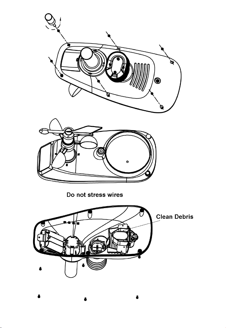
10.1 Advanced Rain Gauge Cleaning
If the rain gauge stops updating, it is possible for spiders and other insects to
nest inside the sensor array housing and interfere with the rain gauge
mechanism.
1. Remove the six screws on the bottom of the sensor array..
2. CAREFULLY separate the top housing from the bottom housing. They
cannot be completely separated due to wires. DO NOT STRESS THE
WIRES. Open the sensor housing slightly, like a clam shell.
3. Clean any debris and spider webs, as shown in below figure.
46
47
11. Southern Hemisphere - Wind Direction Re-Calibration
Product: Professional Wireless Weather Station
This weather station can be used in both the Northern and Southern
Hemispheres.
The cardinal directions (N, S, E, W) molded on the body of the outdoor sensor
are indic ators for the Nor thern Hemisphere only. For Southern Hemisphere
installations, ignore these and face the solar panel to the North when it comes to
installing the outdoor sensor.
Wind Direction
Recalibration: The following procedure is a recalibration guide for the Southern
Hemisphere.
Step 1: Attach the wind vane to the outdoor sensor as described in the User
Manual. Note, the wind vane and the shaft have a flat side and must be lined up
together.
Step 2: Insert the batteries in the battery compartment as described in the User
Manual.
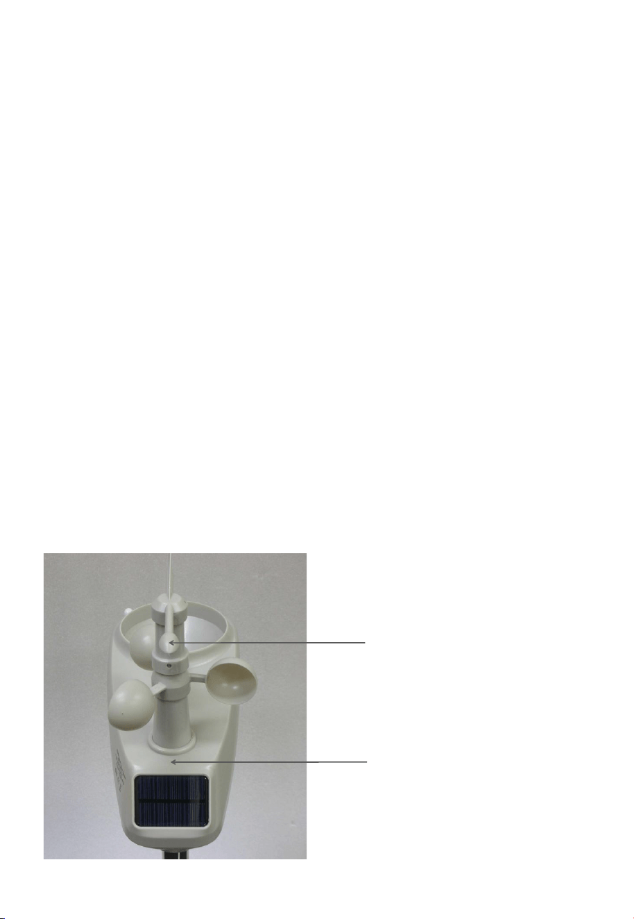
Step 3: Align the wind vane pointer with the ‘S’ marker on the molded body of
the outd oor sensor. Use sticky tape or similar to prevent movement.
This is to simulate a North wind direction. Refer photo.
Align wind vane
pointer with S
‘S’ Marker

48
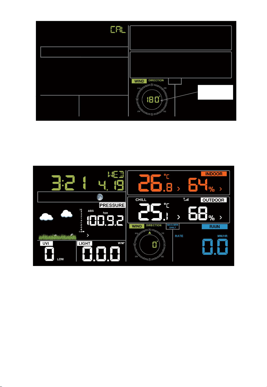
Step 4: Connect the power adapter to the LCD Screen’s power socket. The
display will then power up.
The LCD will begin to register the outdoor sensor and receive weather data.
Refer photo.
Note, the wind direction will read approximately 180º S. This needs to be
recalibrated for the Southern Hemisphere.
Step 5: Press the TEMP Key and MAX/MIN key to enter calibration mode.
Refer photo.
Use the Set Key switch to the Wind Direction calibration value which will be
approximately 180º. This value is for the Northern Hemisphere.
TEMP Key and MAX/MIN key
49
Use the WIND /+ and PRESSURE/- Keys to set this val ue to 0º.
Press the Return Key to go back to the Normal Display Mode. The wind
direction should now read 0º North. Refer photo.
Make sure you r emove the sticky tape from the wi nd vane.
Step 6: Install the Outdoor Sensor outside (and in a sunny position) and
face the solar panel North.
Set to 0

50
12. Troubleshooting Guide
Problem
Solution
Outdoor sensor
array does not
communicate
to the display
console.
The sensor array may have initiated properly and the data is
registered by the console as invalid, and the console must be
reset. Press the reset button as described in Section 5.3.
With an open ended paperclip, press the reset button for 3 seconds
to completely discharge the voltage.
Take out the batteries and wait one minute, while covering the solar
panel to drain the voltage.
Put batteries back in and resync
the console with the sensor array
about 10 feet away.
The LED next to the battery compartment will flash every 16
seconds. If the LED is not flashing every 16 seconds…
Replace the batteries in the outside sensor array.
If the batteries were recently replaced, check the polarity. If the
sensor is flashing every 16 seconds, proceed to the next step.
There may be a temporary loss of communication due to reception
loss related to interference or other location factors,
or the batte
ries may have been changed in the s ensor array and
the console has not been reset. The solution may be as simple as
powering down and up the console (remove AC power and
batteries, wait 10 seconds, and reinsert AC power and batteries).
Temperature
sensor reads
too high in the
day time.
Make certain that the sensor array is not too close to heat
generating sources or strictures, such as buildings, pavement,
walls or air conditioning units.
Use the calibration feature to offset installation issues related to
radiant heat sources. Reference Section 6.7.
Relative
pressure does
not agree wi th
official
reporting
station
You may be viewing the absolute pressure, not the relative
pressure.
Select the relative pressure. Make sure you properly calibrate the
sensor to an official local weather station. Reference Section 6.4.4
for details.
51
Rain gauge
reports rain
when it is not
raining
An unstable mounting solution (sway in the mounting pole) may
result in the tipping bucket incorrectly incrementing rainfall. Make
sure you have a stable, level mounting solution.
Data not
reporting to
Wunderground.
com
1. Confirm your password or key is correct. It is the password
you registered on Wunderground.com. Your
Wunderground.com password cannot begin with a
non-alphanumeric character (a limitation of
Wundeground.com, not the station). Example, $oewkrf is not
a valid password, but oewkrf$ is valid.
2. Confirm your station ID is correct. The station ID is all caps,
and the most common issue is substituting an O for a 0 (or
visa versa). Example, KAZPHOEN11, not KAZPH0EN11
3. Check your router firewall settings. The console sends data
via Port 80.
No WiFi
connection
1. Check for WiFi symbol on the display. If wireless
connectivity is successful the WiFi icon will be displayed
in the time field.
2. Make sure your modem WiFi settings are correct (network
name, and password).
3. Make sure the console is plugged into AC power. The console
will not connect to WiFi when powered by batteries only.
4. The console only supports and connects to 2.4 GHz routers. If
you own a 5 GHz router, and it is a dual band router, you will
need to disable the 5 GHz band, and enable the 2.4 GHz
band.
5. The console does not support guest networks.