Loading ...
Loading ...
Loading ...
1414
For the Installer
6.2 main Wall contRol
The only main wall controls compatible with these units are the X-Touch and Gold-Touch. Only one main wall control can be installed
for each unit.
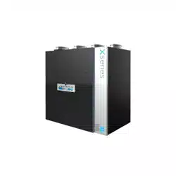
Proceed as follows to connect the main wall control cable to the 4-position terminal block:
1. Strip the end of the cable.
2. Strip 1/4” off the end of the 4 wires. Do not strip longer than required.
3. Using a small flat blade screwdriver, connect each wire to its corresponding
terminal by referring to the labels on the unit (YELLOW to Y; BLACK to B; RED
to R; GREEN to G).
4. Reinstall the terminal block on the electronic board.
5. Refer to the controls’ installation sheet for information on how to operate it.
7. ELECTRICAL CONNECTION TO THE FURNACE
⚠WARNING
Never connect a 120-volt AC circuit to the terminals of the furnace interlock (standard wiring). Only use the low
voltage class 2 circuit of the furnace blower control.
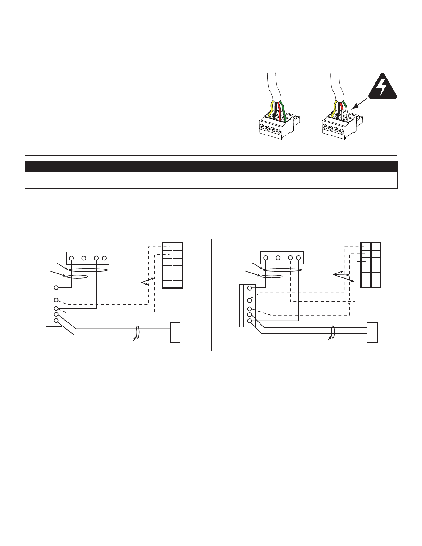
For a furnace connected to a cooling system:
On some older thermostats, energizing the “R” and “G” terminals at the furnace has the effect of energizing “Y” at the thermostat and
thereby turning on the cooling system. If you identify this type of thermostat, you must use the alteRnate FuRnace inteRlock WiRing.
W
Y
R
G
Y
C
UNIT TERMINAL CONNECTOR
THERMOSTAT
TERMINALS
COOLING SYSTEM
NO C NC I OC OL
WRGY
W
R
Y
R
G
Y
C
THERMOSTAT
TERMINAL
4 WIRES
2 WIRES
heating only
FURNACE
24-VOLT
TERMINAL BLOCK
2 WIRES
COOLING SYSTEM
NO
NC
C
UNIT TERMINAL CONNECTOR
VE0350A
NO C NC I OC OL
WRGY
4 WIRES
2 WIRES
heating onl
y
FURNACE
24-VOLT
TERMINAL BLOCK
2 WIRES
LOW VOLTAGE
CLASS 2
LOW VOLTAGE
CLASS 2
STANDARD FURNACE INTERLOCK WIRING ALTERNATE FURNACE INTERLOCK WIRING
VE0354
Loading ...
Loading ...
Loading ...