Loading ...
Loading ...
Loading ...
1313
For the Installer
6. WALL CONTROLS
⚠WARNING
Always disconnect the unit before making any connections. Failure to disconnect power could result in electric
shock or damage to the wall control or electronic module inside the unit.
CAUTION
Failure to comply with the following can cause erratic operation of the unit and/or the wall control:
Never install more than one main wall control per unit. Make sure that the wires do not short-circuit between
themselves or by touching any other components on the wall control. Avoid poor wiring connections. To reduce
electrical interference (noise) potential, do not run wall control wiring next to control contactors or near light
dimming circuits, electrical motors, dwelling/building power or lighting wiring, or power distribution panel.
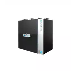
The terminal blocks needed to connect the wall controls are already installed on the electronic
board. To access them, open the unit’s side panel and remove the terminal blocks from the elec-
tronic board.
Run the wall control wires through the grommet before connecting them to the terminal blocks.
6.1 auxiliaRy Wall contRolS
Up to 5 20/40/60-minute auxiliary wall controls can be installed with this unit.
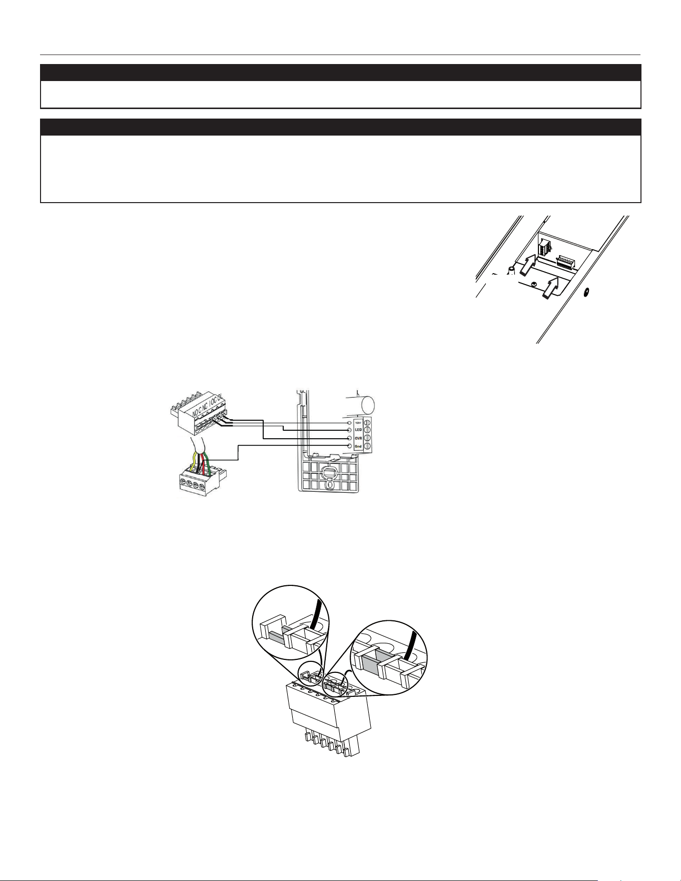
Proceed as follows to connect the auxiliary wall control cable(s) to the 6-position terminal block:
1. Strip the end of the cable.
2. Strip 1/4" off the end of 3 of the wires.
3. Insert the wires in their corresponding holes. A wire is correctly inserted when its orange receptacle is lower than another one
without wire. On illustration below, wire A is correctly inserted, but wire B is not.
4. Reinstall the terminal block on the electronic board.
5. Refer to the controls’ installation sheet for information on how to operate them.
VE0353
A
B
VE0292
Main
control
Auxiliary
control(s)
Grommet
VC0237
NOTE: The auxiliary wall control can be used with a
3-wire connection by removing the LED signals. This
optional wiring will not allow an installation with more
than 1 auxiliary wall control to properly synchronize
their LEDs on an event requested from a peer. Only the
auxiliary wall control having requested the timer event
will have the LEDs updated accordingly.
Loading ...
Loading ...
Loading ...