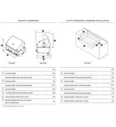
Loading ...
Loading ...
Loading ...
19
INSTALLATION
Gas hook-up
Natural gas hook-up
IMPORTANT!
Where the appliance is intended to be permanently connected to a reticulated supply of gas, the
appliance inlet connection shall have a thread in accordance with AS ISO 7.1.
For Grills mounted on a mobile cart using a flexible hose to connect to a reticulated LPG or NG
fixed outlet gas supply, a restraining device, chain or tether no longer than 80% of the flexible hose
length must be fitted to prevent movement and accidental strain.
The tether must be fixed to within 50mm of the gas connection point. The flexible hose must not
kink, crush, or twist (as required by the current version of AS/NZS 5601.1) in order to prevent ten-
sion on the flexible hose in case the cart should move during use. Quick connect devices should be
certified to AS4627 and gas hose assemblies should be certified to AS/NZS 1869.
Operating pressure: 1 kPa Supply pressure: 1.25 kPa to 3.5 kPa. If in excess of 3.5 kPa, a step down
regulator is required. Check with your local gas utility company or local codes for instructions on
installing gas supply lines. Be sure to check on type and size of run (refer to the current version of
AS/NZS 5601.1 for pipe sizing details), and how deep to bury the line. If the gas line is too small, the
grill will not function properly. Any joint sealant used must be an approved type.
Checking the gas pressure
1 Turn off the gas supply.
2 Connect the pressure gauge to the pressure test point. This can be done by either removing the test
point screw on the NG regulator or by removing one of the burners and measuring the test point
pressure at the injector.
3 Once the gauge is in position, turn the gas supply on.
4 Ignite all grill burners and turn the knob to the “HI” position. Check that the reading measures 1.00 kPa
for Natural gas. If not, adjust the regulator to obtain the stated pressure.
5
Once the pressure is set, switch off the burner, turn off the gas supply, and disconnect the pressure gauge.
6 Ensure the Grill is returned to its normal operating state. Replace the screw in the NG regulator, or
replace the burner if it has been removed. Perform a gas leak check on all gas connections to make
sure there are no gas leaks at the test point or at any point in the connection to the inlet manifold.
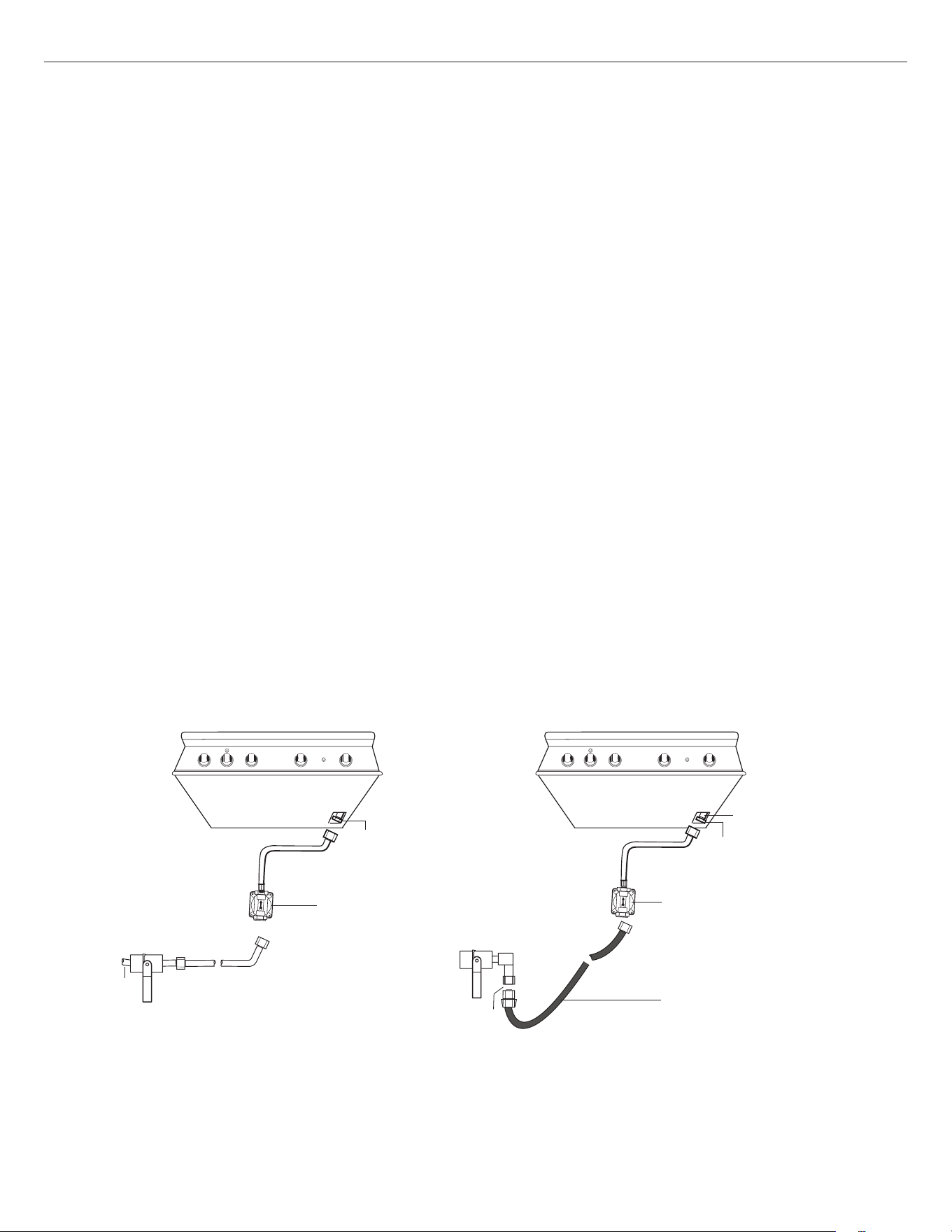
Elbow 45
°
1/2” female
NPT & hose
(installed on the unit)
Unattach hose
from elbow
Quick-connect
gas supply
Elbow 45
°
1/2” female
NPT & hose
(installed on the unit)
NG Regulator 1
kPa (4.0" W.C.)
Gas supply
Bottom of unit
Installer supplied
shut-off valve must be
easily accessible
Installer supplied
shut-off valve must be
easily accessible
NG Regulator 1
kPa (4.0" W.C.)
Installer supplied
Quick connect gas
hose assembly
Bottom of unit
Fig. 08b - Connection using a special quick-connect flexible hose (for mobile
cart-mounted grills being connected to a reticulated supply of Natural gas)
Fig. 08a - Connection with rigid piping
Loading ...
Loading ...
Loading ...