Loading ...
Loading ...
Loading ...
Chapter 5 To Trigger the Oscilloscope RIGOL
MSO2000A/DS2000A User’s Guide 5-3
Trigger Mode
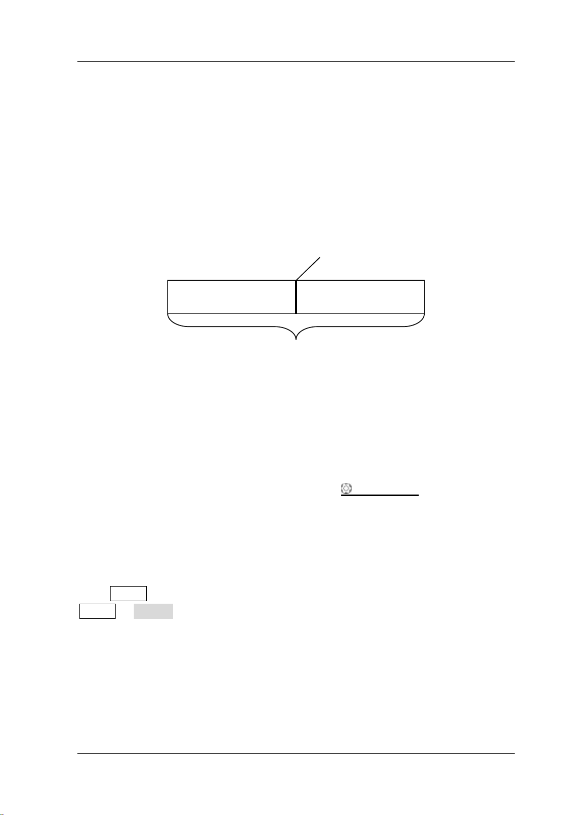
Trigger mode affects the way in which the oscilloscope searches for the trigger. The
following is the schematic diagram of the acquisition memory. As shown in the figure
below, the position of the trigger event is determined by the reference time point and
the delay setting.
Note: The acquisition memory of the oscilloscope is a cyclic buffer and the new data
would overwrite the old data until the acquisition finishes.
Figure 5-1 Schematic Diagram of the Acquisition Memory
Pre-trigger/ Delayed trigger:
Acquire data before/after the trigger event. The trigger position is usually at the
horizontal center of the screen. In full-screen display, seven-grid pre-trigger and
delayed trigger information are displayed respectively. You can adjust the horizontal
position of the waveform through HORI ZONTAL
POSI TI ON to view more
pre-trigger information or delayed trigger information, through which the signal
information before/ after the trigger (such as capture the glitch generated by the
circuit and analyze the pre-trigger data to find out the reasons for glitch) can be
obtained.
Press MODE in the trigger control area (TRIGGER) at the front panel or press
MENU Sweep to select the desired trigger mode. The corresponding status light
of the mode currently selected turns on.
Auto:
After this mode is selected, the oscilloscope starts searching for trigger signals that
meet the specified condition. If trigger signals that meets the specif ied condition are
found, “T’D” is displayed at the upper-left corner of the user interface and stable
Pre-trigger Buffer Delayed Trigger Buffer
Trigger Event
Acquisition memory
Loading ...
Loading ...
Loading ...