
Loading ...
Loading ...
Loading ...
8808A
Users Manual
A-4
Table A-2. Sample Dual Display Applications (cont.)
Primary
Display
Secondary
Display
Applications
REL Resistance • Select and sort resistors. (See also "Using the Compare Function"
in Chapter 3.)
HOLD Actual Value • Show actual measurement while holding a previous, stable
measurement on the primary display
8808A
5-1/2 DIGIT MULTIMETER
HI
LO
1000V
750V
2W/4W
MAX
INPUT SENSE
HI
LO
4
W
10 A
mA
200 mA
MAX
10 A
MAX
1000V CAT I
600 V CAT II
500 V pk
V
1V
300V
eue27.eps
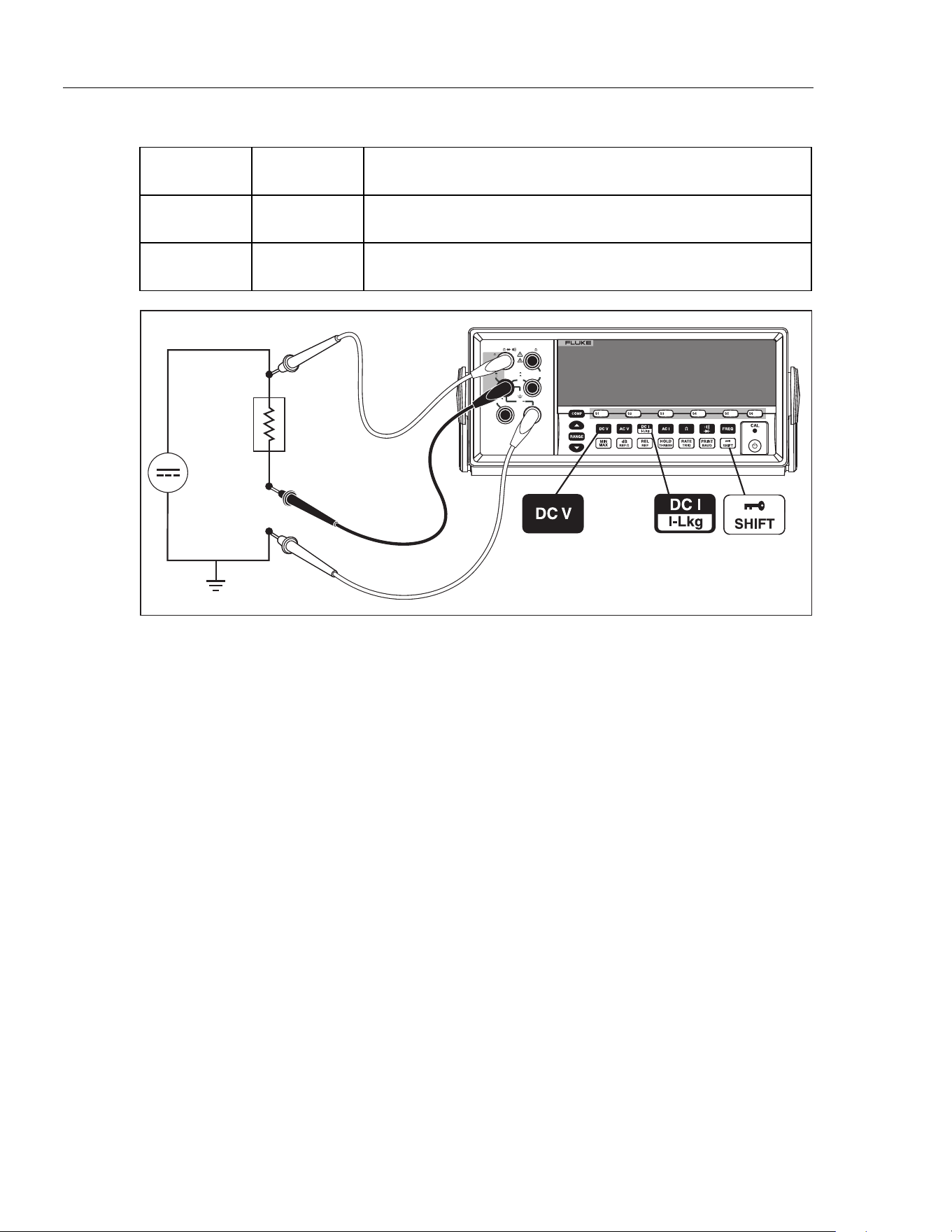
Figure A-2. DC Voltage and DC Current Measurement on Input Signal
The lead from the internal measuring circuitry of the meter to the LO terminal (on the
front panel) is the same for both voltage and current measurements. The resistance of this
lead is approximately .003 ohm. If current is being measured, therefore, a voltage drop
will occur in the resistance that is common to both circuits. This internal resistance, when
added to the external resistance of the lead from the COM input terminal will affect the
accuracy of the voltage reading. For instance, if the external lead resistance is .007 ohm,
the "total" common resistance is .010 ohm. If there is 1 A of current, the voltage reading
would be affected by:
(1 A x.01ohm ) = .01 V or 10 m V.
Depending on the circumstances, this may be significant.
If you want to measure dc voltage on an input signal in the primary display and dc
current in the secondary display, proceed as follows:
1. Turn the Meter on.
2. Press D to select the dc voltage function for the primary display.
3. Press Q then E to select the dc current function for the secondary display.
4. Connect the leads to the test circuit as shown in Figure A-2 and read the
measurements on the display. Although current will be displayed as negative, it is in
fact positive when interpreted according to current flow convention.
Response Times
Response time is the time between a change in an input and when that change is
displayed. The meter’s response time depends on many factors: the measurement
1.888.610.7664 sales@GlobalTestSupply.com
Fluke-Direct.com
Loading ...
Loading ...
Loading ...