
Loading ...
Loading ...
Loading ...
8808A
Users Manual
3-16
HI
LO
1000V
750V
2W/4W
MAX
INPUT SENSE
HI
LO
4
W
10 A
mA
200 mA
MAX
10 A
MAX
1000V CAT I
600 V CAT II
500 V pk
V
1V
300V
eue16.eps
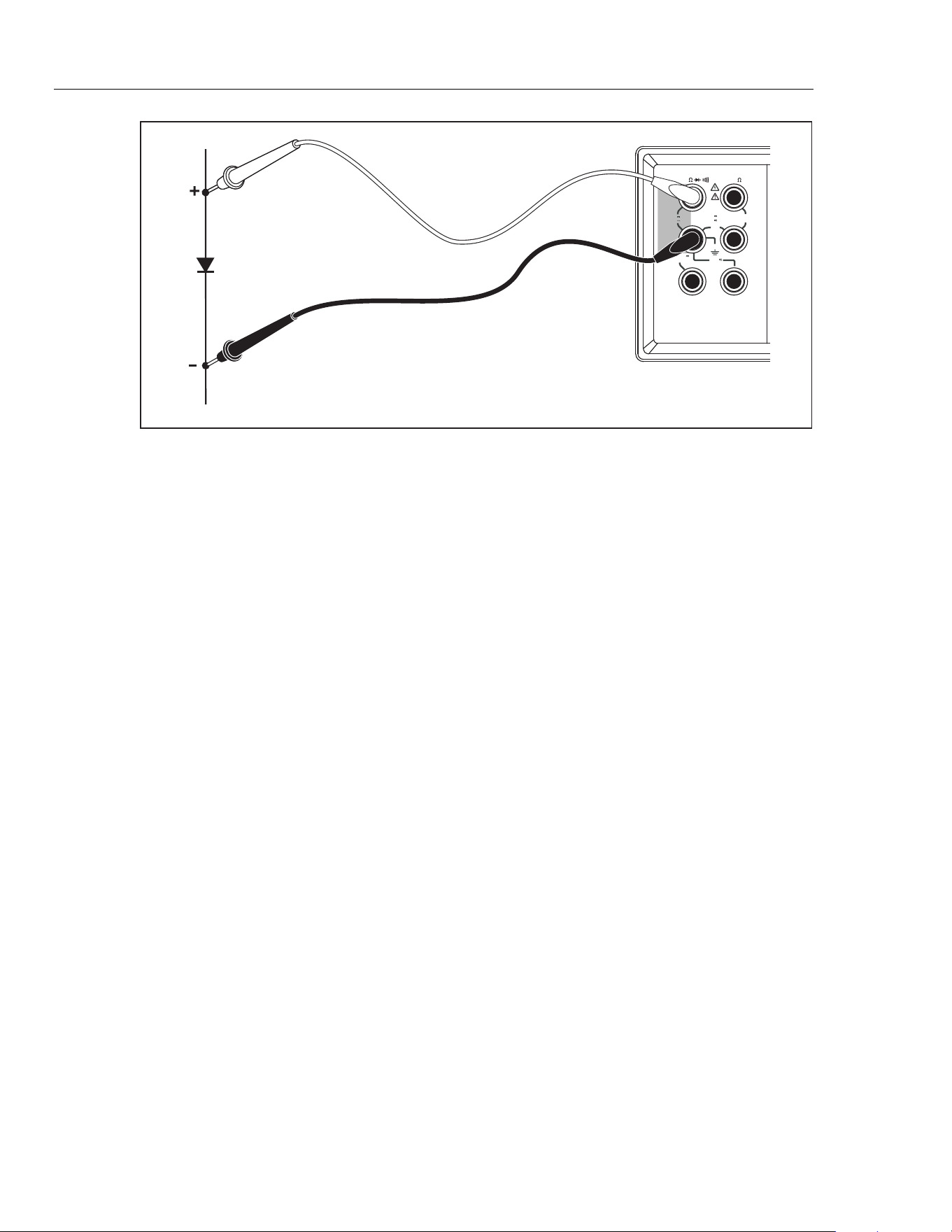
Figure 3-11. Diode Test
Making a Triggered Measurement
The Meter features a trigger function that allows you to select a measurement trigger
source. When the trigger mode is set to 3 or 5, the delay between receiving the trigger
and the start of a measurement is 400 ms. Refer to Chapter 1 for trigger delay response
specifications. Upon completion of each measurement, a “measurement-complete” signal
(low-true pulse) is sent to the external trigger terminal on the rear panel. See the
“Electrical Specifications” section in Chapter 1 for information on this signal.
The following sections discuss triggering the Meter automatically using its internal
trigger, or externally using the trigger key on the front panel and the trigger terminal on
the rear panel.
Setting the Trigger Mode
There are five possible sources for triggering a measurement:
• Mode 1 is automatic. Measurements are triggered internally and are continuous
and occur as fast as the configuration will allow.
• Mode 2 is triggered without delay using J.
• Mode 3 is triggered with delay using J.
• Mode 4 is triggered without delay by an external signal.
• Mode 5 is triggered with delay by an external signal.
To select a trigger source:
1. Press Q then J.
2. Press U or V to choose the trigger mode.
3. Press R and hold for 2 seconds to save the selected mode.
Connecting to an External Trigger
The Meter provides two external trigger connection methods for different operation
modes. Table 3-4 shows the layout of the TRIG/IO_RS232 connector.
1.888.610.7664 sales@GlobalTestSupply.com
Fluke-Direct.com
Loading ...
Loading ...
Loading ...