- OR - - OR -
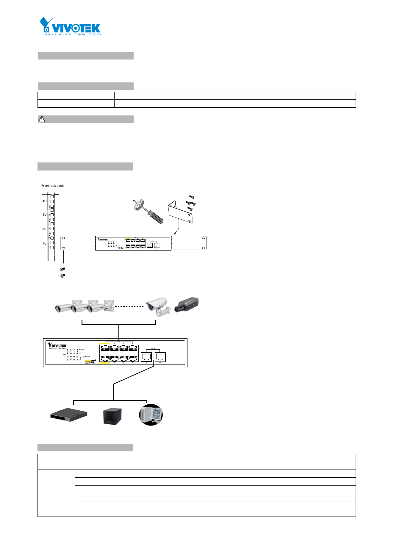
ConsoleNVRRouter / switch
1. Install the PoE switch in a ventilated and dry place that is free of electromagnetic source, vibration, moisture, and dust.
2. Make sure the ventilation openings on the switch are not blocked.
3. Use CAT5 or 6 UTP/STP cables.
4. AC input (100~240V/AC, 50~60Hz), for a max. consumption of 120W.
AW-FET-100C-120 PoE Switch
Quick Installation Guide
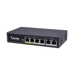
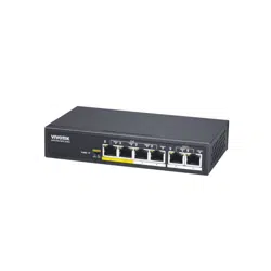
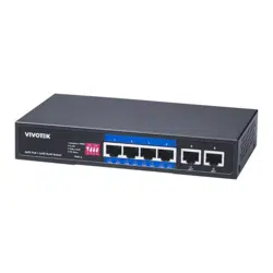
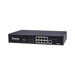
The AW-FET-100C is a 8xFE PoE + 2xFE unmanaged PoE switch capable of feeding 15.4/30W (54V max. per port)
power to Power over Ethernet (PoE) devices. The switch is capable of a total of 115 Watts power budget.
IMPORTANT:
INTRODUCTION
LED DEFINITIONS
CONNECTION
* 1x PoE switch * 1x Quick Installation Guide
* 2x rack mount ears * 1x power cord (type by the shipped-to area)
PACKAGE CONTENTS
Rack-mounting
Connections
Power Green ON Power is on and normal.
Green OFF Power is off.
LINK/ACT Green ON Ethernet port is connected.
Blinking Data is being transmitted or received.
Green OFF No connection.
PoE Orange ON Port is linked to a powered device.
Blinking Abnormal power supply is detected
Orange OFF No device is connected.
VIVOTEK INC.
6F, No.192, Lien-Cheng Rd., Chung-Ho, New Taipei City, 235, Taiwan, R.O.C.
VIVOTEK USA, INC.
2050 Ringwood Avenue, San Jose, CA 95131
VIVOTEK Europe
Randstad 22-133, 1316BW Almere, The Netherlands
T: +31(0)36-5298-434 E: [email protected]
All specications are subject to change without noice.
Copyright © 2017 VIVOTEK INC. All rights reserved.
EXTENSIVE MODE DIP SWITCH
ST Mode: normal communication between port 1~10.
ST VLAN: 1-8 port can be isolated each other but 1-8 port can connect to 9~10 port after open VLAN to stop broadcast
Storm to increase forwarding rate of frame.
EX Mode: 1-8 port can be isolated each other but 1-8 port can connect to 9~10 port after open VLAN to stop broadcast
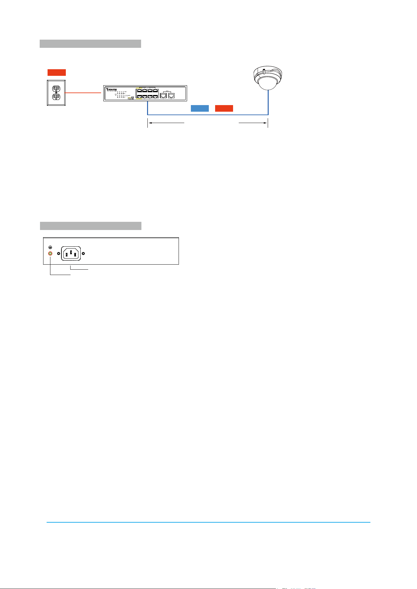
storm to increase forwarding rate of frame. The EX mode(Port 1 & 2), Up to 200m PoE distance allows you to expand
you network via Ethernet cable to where there is no power line or outlet but where you want to x device such as IP
Camera.
• EX mode reaches 802.3af/at(15.4W/30W) camera up to 200m@10Mbps via EXPoE ports
Restart the switch after changing the Extensive mode.
Power
200 meters (656 feet)
PowerData &
EXtensive Mode
802.3af/at PoE Camera
GROUNDING COLUMN
50/60Hz, 2.5A Max
100-240V AC
Power Socket
Grounding Column
The switch already comes with lightning protection mechanism. You can also ground the switch through the PE (Protecting
Earth) cable of AC cord or with Ground Cable.