2
CAUTION:
REFER SERVICING TO QUALIFIED SERVICE PERSONNEL.
UNPACKING:
Unpack carefully. Electronic components can be damaged if improperly handled or
dropped. If an item appears damaged in shipment, place it properly in its carton and
notify the shipper.
1. The electrical connections and conduit installations shall be made by a certied electrician following
local regulations.
2. Risks of electric shock exist. The mains supply shall be disconnected before installation.
3. Read and follow Instructions: All operating and user instructions should be read and followed before
the unit is to be operated.
4. This product relies on the building's installation for short-circuit (overcurrent) protection. Ensure that
the protective device is listed rated not greater than 20A.
5. Attach the ground wire (to external ground) to a suitable grounding point, e.g., an earth stake.
6. Observe national and local regulations for the installation.
7. To avoid additional accummulation of moisture, please avoid installing the components in cabinet
during a raining weather.
8. Only use applicable tools when installing this product; excessive force can damage the product.
9. Use only accessories compliant with the technical specications of the product.
10. When the need arises for transportting this product, it is recommended to use the original shipping
package.
IMPORTANT!:
Revision History:
Rev. 1.0: Initial release.
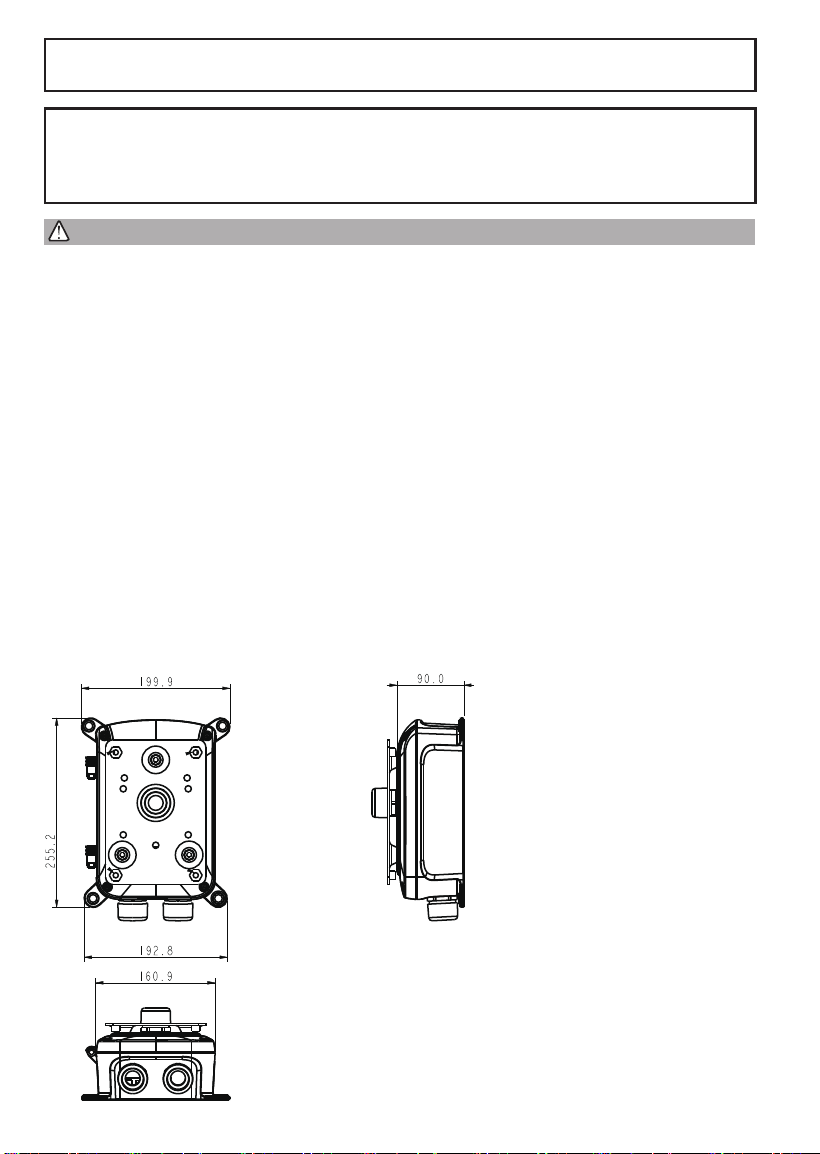
Mechanical Dimensions:

3
English
Applicable Mount & Brackets
I
Item Models Applicable Cameras
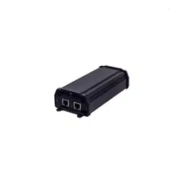
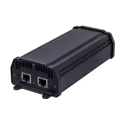
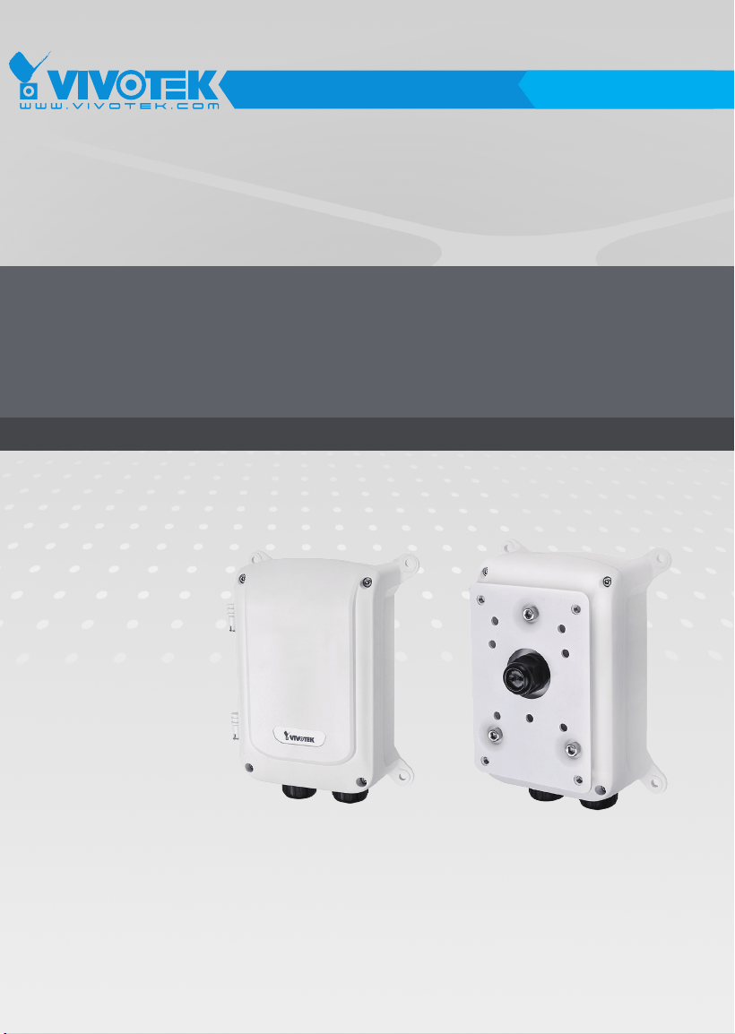
Junction box AP-GIC-015B-095 SD9365, SD9366, SD9363, SD9364
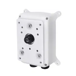
External
housings
AE-239, AE-244, AE-23E, AE-23F Box cameras
100~240V Line IN
Ground
Neutral
to camera
from
network
for power
wires
for Ethernet
cables
Ground
Wiring
II
Route your power wires through a 3/4" conduit into the power box. The wiring scheme is shown below.
The power supply converts 100~240V power to the 95W PoE output to IP cameras.

4
Introduction
The power box can be mounted with the AM-314, AM315 pole-mount, AM-414 corner-mount bracket, or
directly secured to a wall.
III
The power box can be mounted with the external housings, such as the AE-239, AE-244, AE-23E, and
AE-23F.
5
English
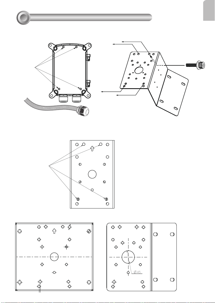
Use the included M10 hex socket screws to secure the power box to a pole-mount or corner mount
bracket.
Installation
IV
M10
3/4” conduit
AM-314
AM-315
AM-414
For this PoE
juncon box
Pole-mount bracket
Pole-mount bracket Corner-mount bracket
The mounting hole denition is illustrated below. The same mounting hole pattern apply to all pole-
mount and corner-mount brackets.
6
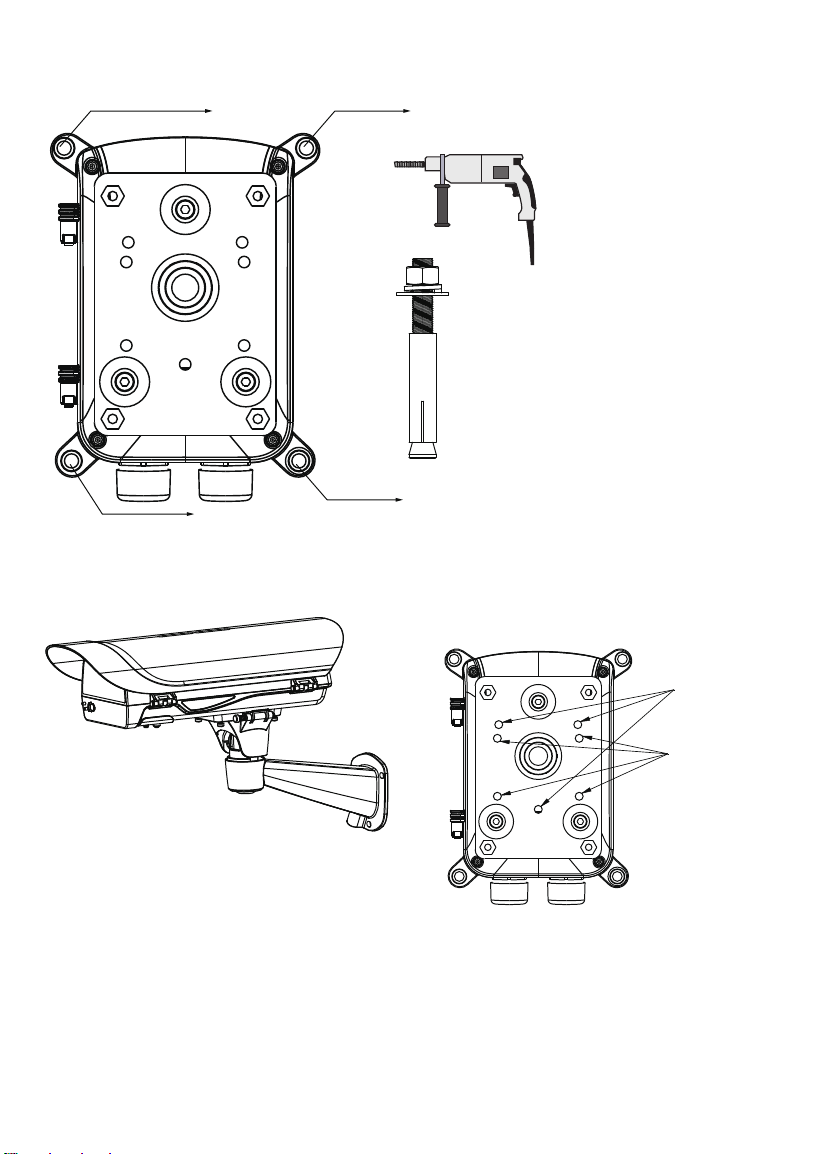
If the power box is directly mounted to wall, drill holes in a diameter of 9.5mm or 3/8", and 4cm deep.
AM-21D
AM-21E
M8
Use the following mounting positions for the camera housings (via AM-21D and AM-21E brackets).

7
English
This page is intentionally left blank.

8
This page is intentionally left blank.