VIVOTEK INC.
6F, No.192, Lien-Cheng Rd., Chung-Ho, New Taipei City, 235, Taiwan, R.O.C.
VIVOTEK USA, INC.
2050 Ringwood Avenue, San Jose, CA 95131
VIVOTEK Netherlands B.V.
Busplein 36, 1315KV, Almere, The Netherlands
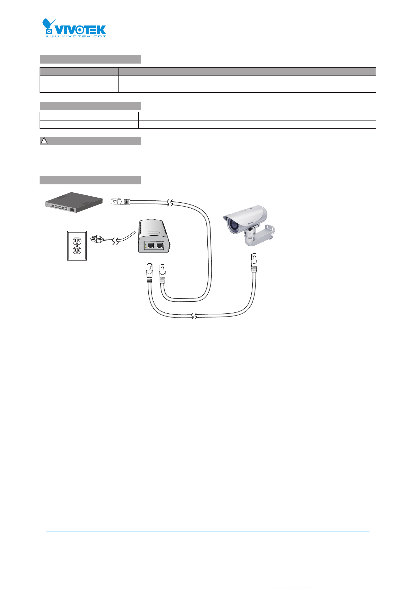
Non-PoE Switch
Data INP+D OUT
100~240V AC
PoE
PWR
1. Use CAT5 or 5e UTP/STP cables.
2. AC input (100~240V/AC, 50~60Hz), for a max. consumption of 19W.
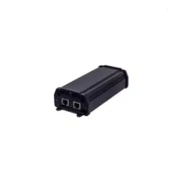
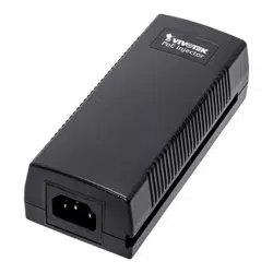
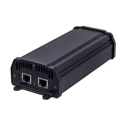
AP-FIC-010A(B)-015 FE PoE Injector
Quick Installation Guide
Model Description
AP-FIC-010A-015 FE Standard 802.3af 15.4W output
AP-FIC-010B-015 FE Passive 15.4W output
IMPORTANT:
INTRODUCTION
CONNECTION
* 1x PoE injector * 1x AC power cord
* 1x Quick Installation Guide
PACKAGE CONTENTS
All specications are subject to change without noice.
Copyright © 2014 VIVOTEK INC. All rights reserved.
Installation Steps:
1. Connect the included AC power cord to the injector. The Power LED (Green) should be lit.
2. Connect the Data IN port to a LAN switch using an Ethernet cable.
3. Connect the Power+Data OUT port to a powered device, i.e., IP camera, using another Ethernet cable. Make sure the
PoE LED (Yellow) is lit.
4. Check if the powered device (IP camera) is working properly. An IP camera may take up to 1 or 2 minutes to power up.