Loading ...
Loading ...
Loading ...

350
the set data match the set relationship condition, trigger on the clock edge of Ack bit after the data byte.
After selecting “EEPROM Data Read”, click the relationship by “=” “ >” “<” “ ≠”, and the setting method
is the same as the address field.
i) 10-bit write frame - Trigger on 10-bit write frame on the 26th clock edge if all bits in the pattern match.
Trigger mode is start condition, SCL connect to Ch2, SDA connect to Ch1, follow these steps as below:
(1) Tap S1 to open the decode channel, and click S1 again to open the bus configuration menu;
(2) Select the bus type as “I2C”, open the bus setting menu, and select the clock SCL as Ch2 channel;
(3) Open the trigger mode configuration menu and click “Start Condition” on the touch screen.
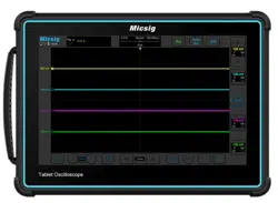
(4) Set the threshold level of two channels according to signal amplitude; I2C trigger graphic interface is
shown in Figure 12-24:
Loading ...
Loading ...
Loading ...