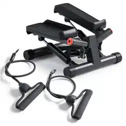
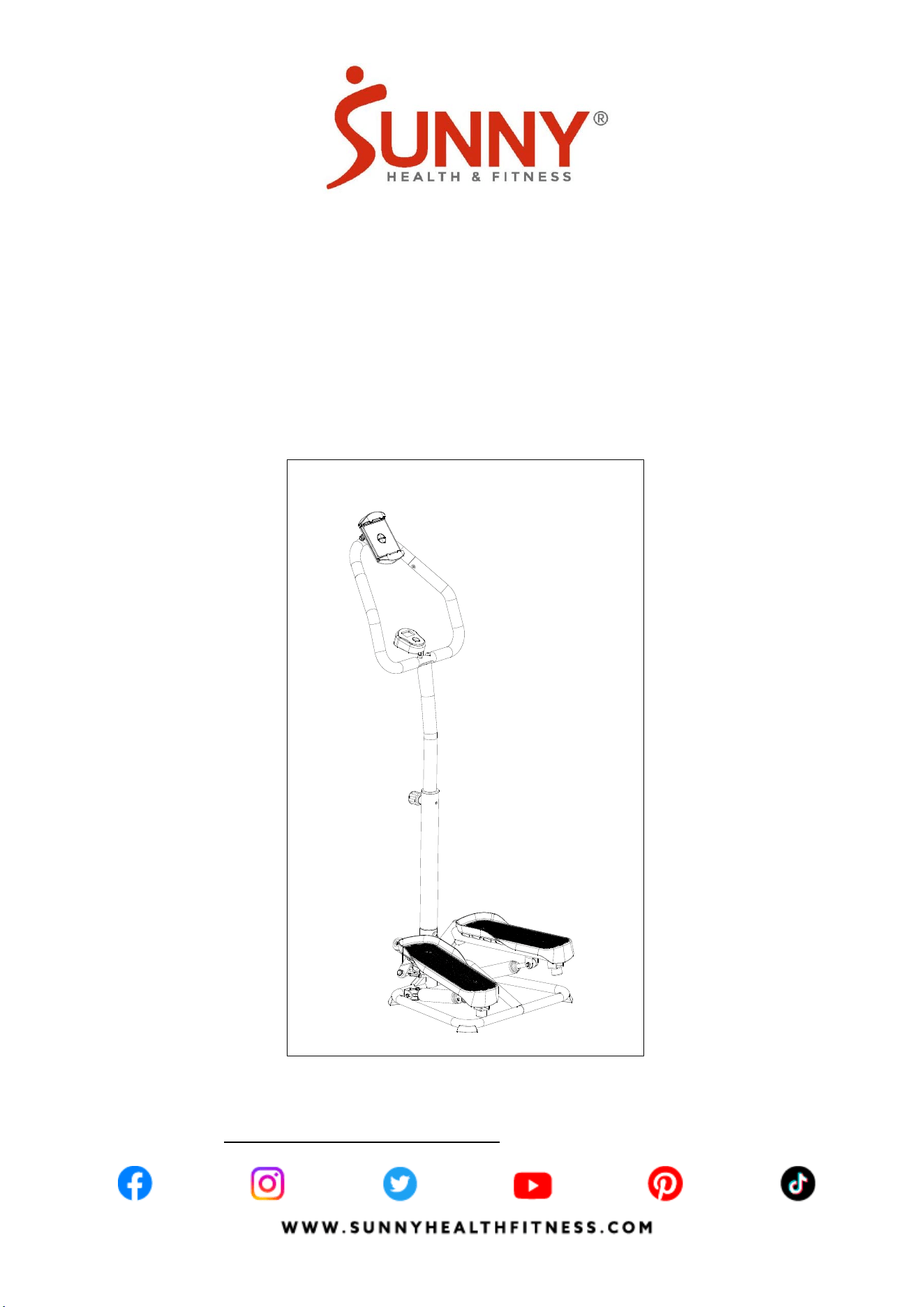
SMART STAIR STEPPER MACHINE
WITH HANDLEBAR
SF-S020027 SMART
USER MANUAL
IMPORTANT! Please retain owner’s manual for maintenance and adjustment instructions. Your
satisfaction is very important to us, PLEASE DO NOT RETURN UNTIL YOU HAVE
CONTACTED US: [email protected] or 1- 877 - 90SUNNY (877-907-8669).

1
IMPORTANT SAFETY INFORMATION
We thank you for choosing our product. To ensure your safety and health, please use this
equipment correctly. It is important to read this entire manual before assembling and using the
equipment. Safe and effective use can only be achieved if the equipment is assembled,
maintained, and used properly. It is your responsibility to ensure that all users of the equipment are
informed of all warnings and precautions.
1. Before starting any exercise program, you should consult your physician to determine if you
have any medical or physical conditions that could put your health and safety at risk or prevent
you from using the equipment properly. Your physician’s advice is essential if you are taking
medication that affects your heart rate, blood pressure, or cholesterol level.
2. Be aware of your body’s signals. Incorrect or excessive exercise can damage your health.
Stop exercising if you experience any of the following symptoms: pain, tightness in your chest,
irregular heartbeat, shortness of breath, lightheadedness, dizziness, or feelings of nausea. If
you do experience any of these conditions, you should consult your physician before
continuing with your exercise program.
3. Keep children and pets away from the equipment. The equipment is designed for adult use
only.
4. Use the equipment on a solid, flat level surface with a protective cover for your floor or carpet.
To ensure safety, the equipment should have at least 2 feet (60 cm) of free space all around it.
5. Ensure that all nuts and bolts are securely tightened before using the equipment. The safety of
the equipment can only be maintained if it is regularly examined for damage and/or wear and
tear.
6. Always use the equipment as indicated. If you find any defective components while
assembling or checking the equipment, or if you hear any unusual noises coming from the
equipment during exercise, discontinue use of the equipment immediately and do not use until
the problem has been rectified.
7. Wear suitable clothing while using the equipment. Avoid wearing loose clothing that may
become entangled in the equipment.
8. Do not place fingers or objects into the moving parts of the equipment.
9. The maximum weight capacity of this unit is 350 lbs (160 kgs).
10. The equipment is not suitable for therapeutic use.
11. To avoid bodily injury and/or damage to the product or property, proper lifting and moving are
required.
12. Your product is intended for use in cool and dry conditions. You should avoid storage in
extreme cold, hot or damp areas as this may lead to corrosion and other related problems.
13. This equipment is designed for indoor and home use only; it is not intended for commercial
use.
2
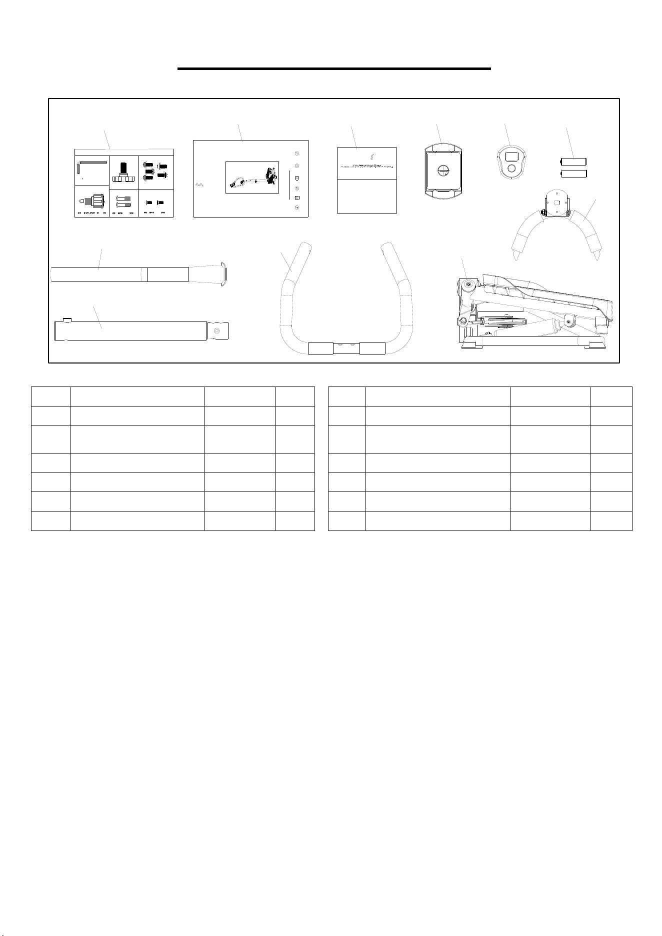
PRE-ASSEMBLY CHECK LIST
Before you start to assemble, please make sure all parts are included.
No. Description Spec. Qty. No. Description Spec. Qty.
1 Main Frame 1 48 Upper Handlebar 1
32-1 Computer
DSC03601-
APP
1 A Hardware Package 1
34 Bottom Handlebar Post 1 B Manual 1
35 Upper Handlebar Post 1 C Thank You Card 1
36 Handlebar 1 D Battery AA 2
42 Device Holder 1
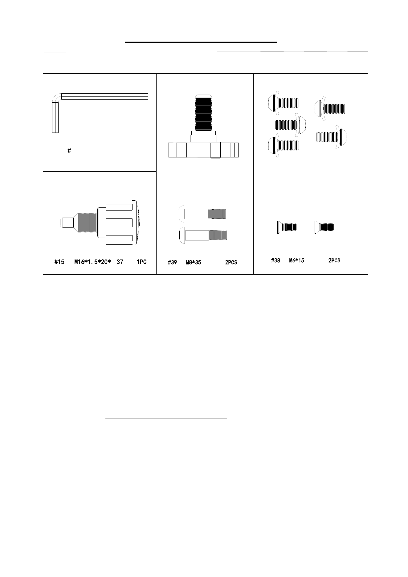
SF-S020027 SMART HARDWARE PACKAGE
Step 2
Step 3
#21 Φ60*M14 1PC
#40 M8*1 6*S5 5PC S
#41 Φ 20*2 5PCS
Step 5
#
3
9
M
8
*
3
5
2
P
C
S
#
55 S5 1PC
Step 4
Step 6
#
3
8
M
6
*
1
5
2
P
C
S
#
1
5
M
1
6
*
1
.
5
*
2
0
*
Φ
3
7
1
P
C
IMPORTANT! Please retain owner’s manual for maintenance and adjustment instructions.
Your satisfaction is very important to us, PLE ASE DO NOT RE TURN UNTIL YOU HAVE
CONTACTED US:
support@sun nyhealthfitness.com or 1-877-90SUNNY (877-907-8669).
A
B
C
4
2
3
2
-
1
D
3
5
3
4
3
6
4
8
1
THANK
YOU
F OR YOUR PURCHASE
UNNY
H E A L T H & F L T N E S S
UNNY
W W W.S U N N Y H E A L T H F I T N E S S.C O M
SMART STAIR STEPPER MACHINE
SF-S020027 SMART
USER MANUAL
H E A L T H & F I T N E S S
3
HARDWARE PACKAGE
Ordering Replacement Parts (U.S. and Canadian Customers only)
Please provide the following information in order for us to accurately identify the part(s) needed:
The model number (found on cover of manual)
The product name (found on cover of manual)
The part number found on the “EXPLODED DIAGRAM”( page 12) page and “PARTS LIST”
(page 13)
Please contact us at support@sunnyhealthfitness.com or 1-877-90SUNNY (877-907-8669).
SF-S020027 SMART HARDWARE PACKAGE
Step 2
Step 3
#21 Φ60*M14 1PC
#40 M8*16*S5 5PCS
#41 Φ20*2 5PCS
Step 5
#
3
9
M
8
*
3
5
2
P
C
S
#
55 S5 1PC
Step 4
Step 6
#
3
8
M
6
*
1
5
2
P
C
S
#
1
5
M
1
6
*
1
.
5
*
2
0
*
Φ
3
7
1
P
C
4
ASSEMBLY INSTRUCTIONS
We value your experience using Sunny Health and Fitness products. For assistance with parts or
troubleshooting, please contact us at support@sunnyhealthfitness.com or 1-877-90SUNNY (877-
907-8669).
1
22
16
1
3
8
#
2
1
Φ
6
0
*
M
1
4
1
P
C
1
2
1
3
4
4
1
4
0
4
6
4
0
4
1
4
0
4
1
4
0
4
1
2
8
#
4
0
M
8
*
1
6
*
S
5
5
P
C
S
#
4
1
Φ
2
0
*
2
5
P
C
S
#55 S5 1PC
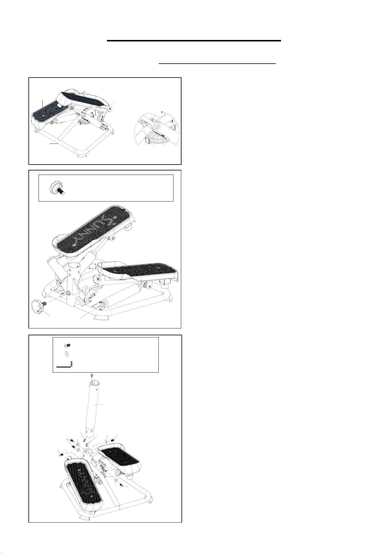
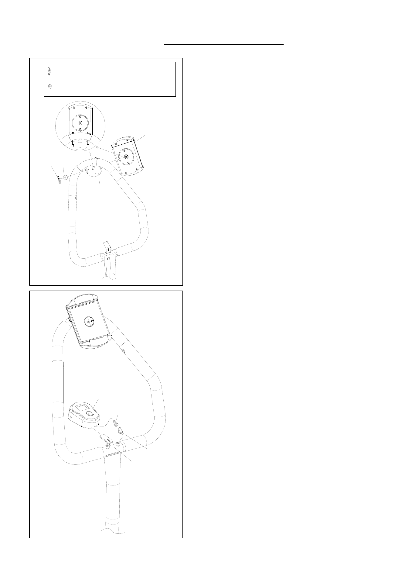
STEP 2:
Then insert the Adjustment Knob (No. 21) into
the Main Frame (No. 1), and adjust the
tightness of the Adjustment Knob (No. 21) to
the desired position.
STEP 3:
Connect the Sensor Wire (No. 28) with the
Extension Wire (No. 46).
Insert the Bottom Handlebar Post (No. 34) into
the Main Frame (No. 1) with 5 Hexagon Bolts
(No. 40) and 5 Curved Gaskets (No. 41).
Tighten with the Allen Wrench (No. 55).
STEP 1:
Remove the Main Frame (No. 1) from the box.
Lift one pedal of Left or Right Pedal (No. 8 or
No. 13) up with your hand and ensure that the
Wire Rope (No. 22) is put in the slot of the
Pulley (No. 16) as shown in the picture.
5
We value your experience using Sunny Health and Fitness products. For assistance with parts or
troubleshooting, please contact us at support@sunnyhealthfitness.com or 1-877-90SUNNY (877-
907-8669).
4
6
4
3
#
1
5
M
1
6
*
1
.
5
*
2
0
*
Φ
3
7
1
P
C
3
4
3
5
1
5
#
3
9
M
8
*
3
5
2
P
C
S
#55 S5 1PC
3
6
3
9
3
5
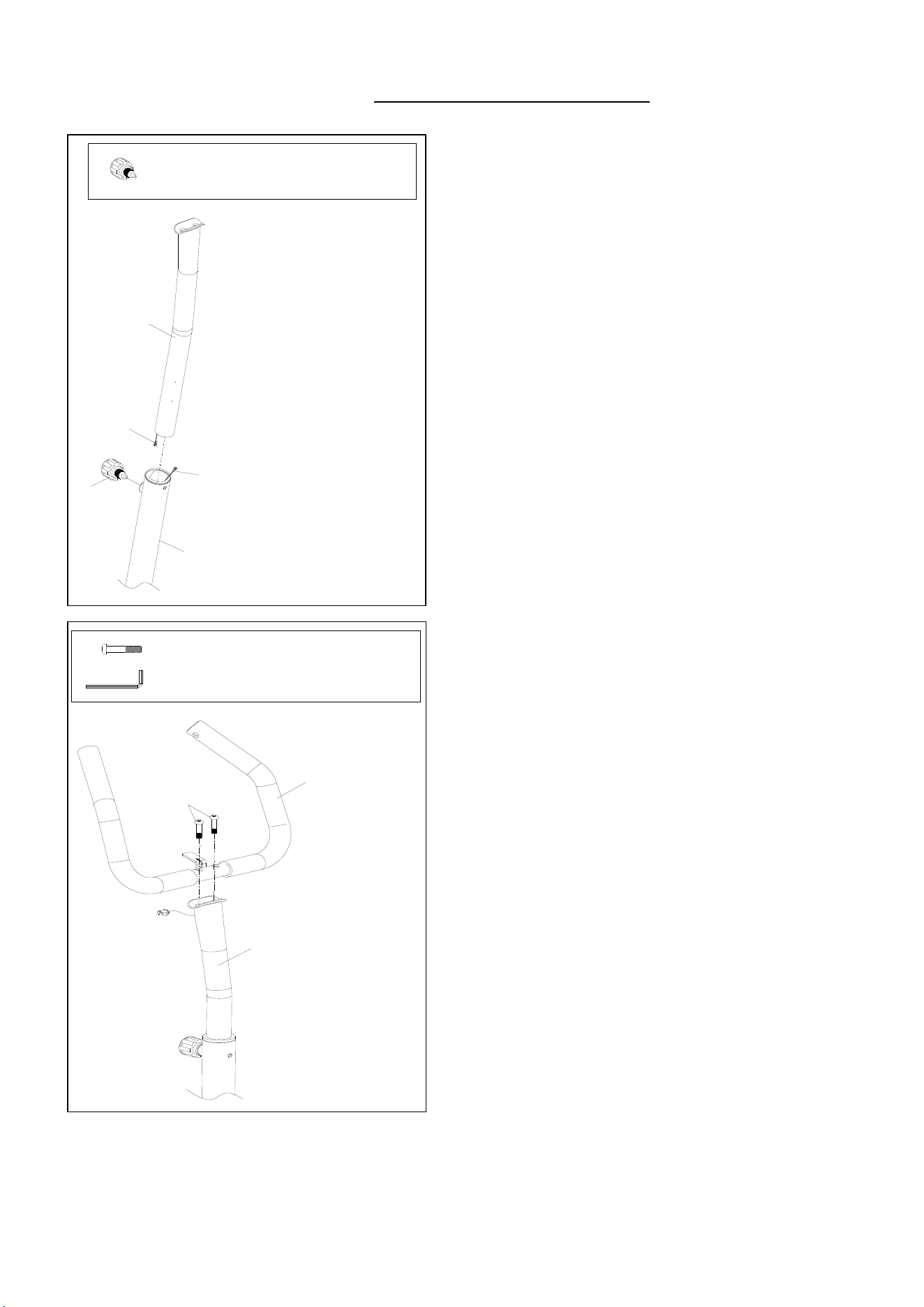
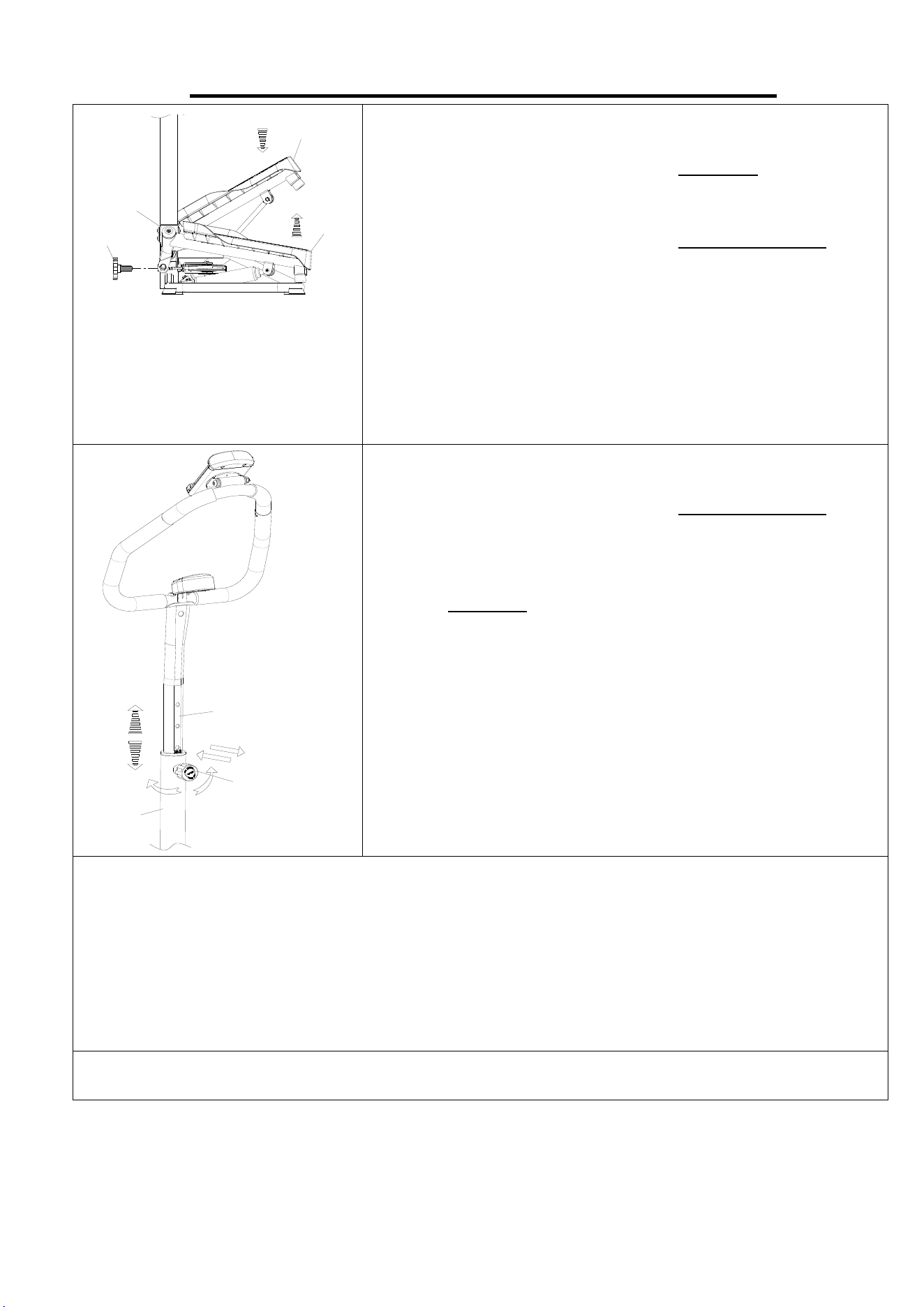
STEP 4:
Connect the Extension Wire (No. 46) with the
Extension Wire (No. 43).
Insert the Upper Handlebar Post (No. 35) into
the Bottom Handlebar Post (No. 34), adjust
the Upper Handlebar Post (No. 35) to desired
height, then secure it in place by inserting and
tightening the Adjustment Knob (No. 15) from
hardware package.
STEP 5:
Attach the Handlebar (No. 36) onto the Upper
Handlebar Post (No. 35) with 2 Hexagon
Bolts (No. 39). Tighten with the Allen Wrench
(No. 55).
6
We value your experience using Sunny Health and Fitness products. For assistance with parts or
troubleshooting, please contact us at support@sunnyhealthfitness.com or 1-877-90SUNNY (877-
907-8669).
S
i
d
e
B
3
6
3
8
4
8
#
3
8
M
6
*
1
5
2
P
C
S
#55 S5 1PC
3
6
4
8
S
i
d
e
A
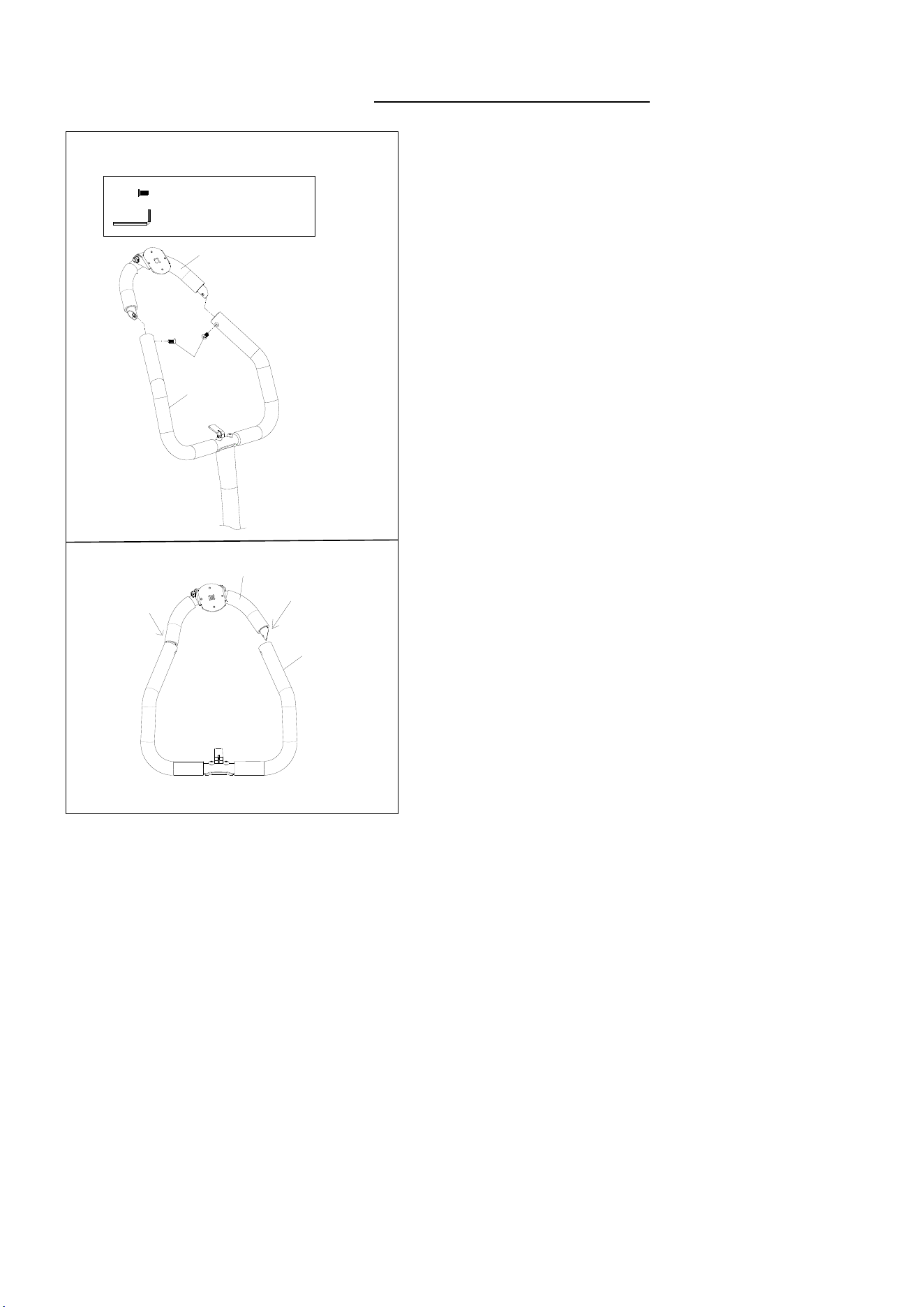
STEP 6:
Attach the Upper Handlebar (No. 48) onto the
Handlebar (No. 36) with 2 Hexagon Bolts (No.
38). Tighten with the Allen Wrench (No. 55).
NOTE: Please attach Side A of the Upper
Handlebar (No. 48) onto the Handlebar (No.
36) first, and then repeat the same step for Side
B.
7
We value your experience using Sunny Health and Fitness products. For assistance with parts or
troubleshooting, please contact us at support@sunnyhealthfitness.com or 1-877-90SUNNY (877-
907-8669).
#
5
2
M
6
1
P
C
#53 Φ18*Φ6.5*1.5 1PC
5
2
5
3
4
2
5
4
32-1
43
3
2
a
36
STEP 8:
Connect the Extension Wire (No. 43) to the
Computer Wire (No. 32a). Then attach the
Computer (No. 32-1) to the bracket of the
Handlebar (No. 36).
The assembly is complete!
STEP 7:
Remove the Butterfly Nut (No. 52) and the
Flat Washer (No. 53) from the Device Holder
(No. 42).
Attach the Device Holder (No. 42) onto the
Bracket (No. 54) using the Butterfly Nut (No.
52) and the Flat Washer (No. 53) that were
removed, tighten and secure with your hand.
NOTE: When assembling the Device Holder
(No. 42), ensure that it is aligned to the
Bracket (No. 54) slot.
8
MAINTENANCE & ADJUSTMENT GUIDE
ADJUSTING THE STEPPING HEIGHT
Turn the Adjustment Knob (No. 21) clockwise to increase
the stepping height.
Turn the Adjustment Knob (No. 21) counter-clockwise to
decrease the stepping height.
NOTE: Before turning the adjustment knob, you need to lift
one pedal of the Left or Right Pedals (No. 8 or No. 13) up
and ensure the cable is around the pulley. If the cable is not
properly positioned around the pulley, it can cause damage to
the main frame of the product or prevent the height from
adjusting correctly.
ADJUSTING THE HEIGHT OF HANDLEBAR
Turn the Adjustment Knob (No. 15) counter-clockwise and
pull it out from Bottom Handlebar Post (No. 34). Adjust the
Upper Handlebar Post (No. 35) to desired position, then
insert and re-tighten the Adjustment Knob (No. 15) by
turning it clockwise.
CLEANING
The stepper can be cleaned with a soft, clean, and damp cloth. Do not use abrasives or solvents
on plastic parts. Please wipe your perspiration off the stepper after each use. Be careful not get
excessive moisture on the computer display panel as this might cause electrical hazards or
electronics failure.
Please keep the stepper, especially the computer, out of direct sunlight to prevent screen
damage.
Please inspect all assembly bolts and pedals on the stepper for proper tightness every week.
STORAGE
Store the stepper in a clean and dry environment, away from children.
NOTES:
The Hydraulic Cylinder (No. 20) may become excessively hot after prolonged use and may be
dangerous to touch. Allow the Hydraulic Cylinder (No. 20) to cool between uses.
1
2
1
8
1
3
1
5
3
5
3
4
9
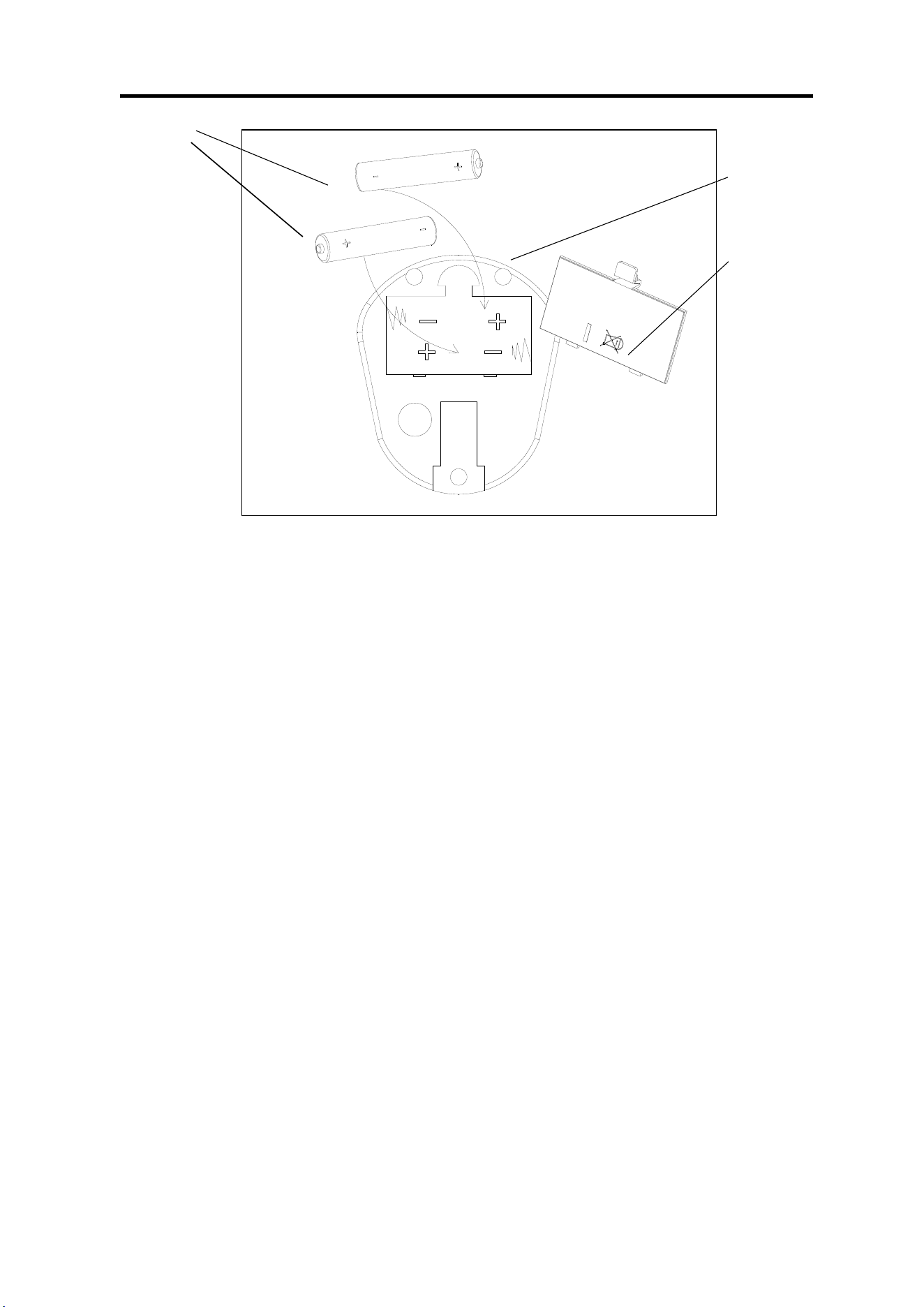
BATTERY INSTALLATION AND REPLACEMENT
BATTERY INSTALLATION:
1. Take out 2 AA batteries from computer box.
2. Press the buckle of battery cover on the Computer (No. 32-1), then remove battery cover.
3. Install 2 AA batteries into the battery case on the back of the Computer (No. 32-1). Pay attention
to the battery + and – poles before installing.
4. Press the buckle of battery cover, then put the battery cover back to the back of the Computer
(No. 32-1).
The installation is complete!
BATTERY REPLACEMENT:
1. Press the buckle of battery cover on the back of the Computer (No. 32-1), then remove battery
cover.
2. Remove the 2 old AA batteries in the battery case and install 2 new AA batteries into the battery
case on the back of the Computer (No. 32-1). Pay attention to the battery + and – poles before
installing.
3. Press the buckle of battery cover, then put the battery cover back to the back of the Computer
(No. 32-1).
The replacement is complete!
NOTE: Always change both batteries at the same time. Do not mix battery types and do not mix
old and new batteries. Dispose battery according to your state and regional guidelines.
Battery Cover
Battery
32-1
10
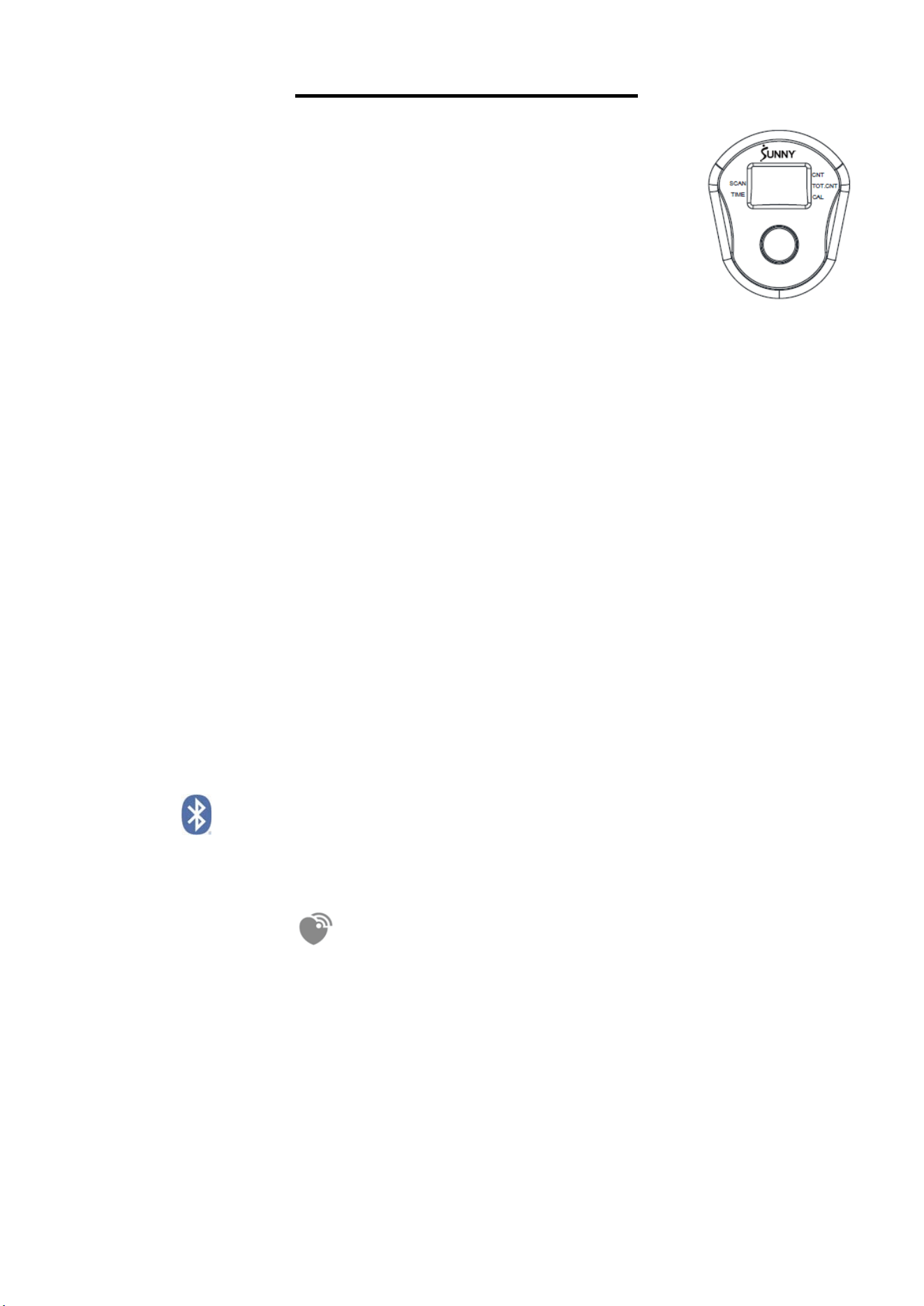
EXERCISE COMPUTER
SPECIFICATIONS:
CALORIES (CAL)-------------------------------0~9999 KCAL
COUNT (CNT)-----------------------------------0~9999
TIME-----------------------------------------------00:00~99:59 MIN/S
TOTAL COUNT (TOT. CNT)-----------------0~9999K
PULSE……………………………………...40-240BPM
KEY FUNCTIONS:
MODE:
1. This key lets you to select and lock on to a particular function you want.
2. Hold the key for 2 seconds to reset all values except TOT.CNT when the Bluetooth is not connected.
3. Press and hold the MODE key for 6 seconds to disconnect from both the SunnyFit APP and the heart
rate monitor; then, the meter will enter sleep mode.
FUNCTIONS:
1. CALORIES (CAL): Display calories burned during exercise.
2. COUNT (CNT): Accumulates the count of steps taken while exercising. Computer counts 1 step after
you step once with each foot.
3. TIME: Display the workout time elapsed during exercise.
4. TOTAL COUNT (TOT. CNT): Display the total steps taken while exercising. To reset TOTAL COUNT
(TOT. CNT), you need to remove the battery and reinsert.
When reach 10,000~99,999 steps: meter will only display 10.00K~99.99K
When reach 100,000~999,999 steps: meter will display 100.0K~999.9K
When reach 1,000,000~9,999,999 steps: meter will display 1000K~9999K
5. PULSE: Displays current heart rate value. The data comes from the matching Bluetooth heart rate
monitor.
6. SCAN: The computer will rotate through the four functions in the following order: CALORIES
(CAL)—TIME—TOTAL COUNT (TOT. CNT)-PULSE. Each function will be held for 6 seconds.
BLUETOOTH :
1. The Bluetooth icon will flash when the meter is on or wakes from sleep mode. If no Bluetooth
connection is established within 3 minutes, the Bluetooth icon will turn off.
2. The Bluetooth icon will stay on when it is connected.
WIRELESS HEART RATE :
1. The wireless heart rate icon will flash when the meter is on. If the heart rate monitor is not connected
within 1 minute, the wireless heart rate icon will turn off.
2. After exercise resumes, the wireless heart rate icon will flash. If the heart rate monitor is not
connected within 1 minute, the wireless heart rate icon will turn off.
3. When the meter wakes from sleep mode, the wireless heart rate icon will flash. If the heart rate
monitor is not connected within 1 minute, the wireless heart rate icon will turn off.
4. The wireless heart rate icon will flash when the MODE key is pressed during exercise. If the heart
rate monitor is not connected within 1 minute, the wireless heart rate icon will turn off.
5. The wireless heart rate icon will stay on when the heart rate monitor is connected.
NOTE: The heart rate monitor is not included. Wireless heart rate function works with SunnyFit Heart Rate
Monitor HR200. HR200 can only connect to the computer when the wireless heart rate icon is flashing.
11
NOTE:
1
. The meter will shut off automatically and disconnect the heart rate monitor if there is no activity
for 4 minutes when the Bluetooth is not connected.
2. When machine is in use, the computer automatically turns on.
3. If computer display is abnormal, please replace the battery and try again.
4. The computer uses 2/AA batteries.
APP CONNECTION:
Connect Smart Equipment to SunnyFit App:
1. Scan to download SunnyFit from the app store:
2. Ensure that the Bluetooth function is turned on from your mobile device.
3. If this is your first time using the SunnyFit app, follow the in-app instructions to register for
your free SunnyFit account and log in.
4. Begin any workout activity that matches your smart equipment, then follow the onscreen
prompts to search for and connect to your smart equipment.
5. When connected, your stats and records will be displayed at the end of your
course/session, and recorded in your account profile!
Troubleshooting:
If you are having trouble connecting your smart equipment, visit www.sunnyfit.com/guide
or scan the QR code below:
If you require additional support, please contact support@sunnyfit.com
12
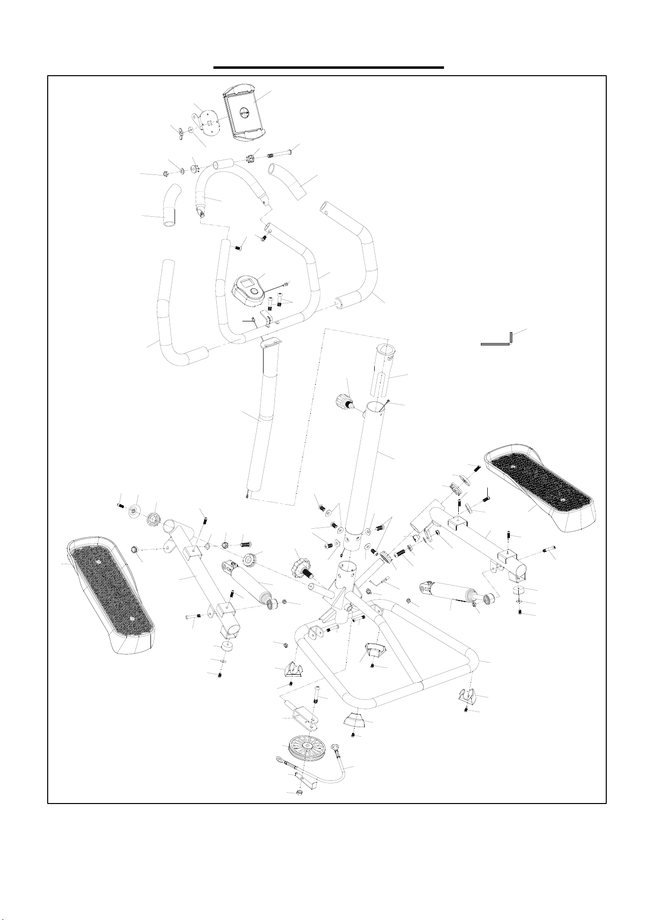
EXPLODED DIAGRAM
3
8
4
7
4
7
1
9
4
9
4
8
5
1
5
2
5
3
4
2
5
0
5
0
5
4
1
1
0
1
0
5
6
7
7
8
9
3
1
0
9
6
7
7
1
1
1
2
1
3
4
1
6
2
0
2
0
2
1
2
2
2
3
2
3
2
4
2
5
2
5
2
6
2
6
2
7
2
7
2
9
3
0
3
0
3
0
3
0
1
1
1
1
1
1
1
1
3
1
3
1
3
1
3
1
2
7
2
7
1
7
2
8
2
3
3
3
3
1
1
5
2
4
1
9
1
8
1
0
3
2
-
1
3
4
3
5
1
4
1
5
3
7
3
6
3
9
4
0
4
0
4
1
4
0
4
1
4
1
4
1
55
4
3
4
5
4
4
3
2
a
3
7
4
6

13
PARTS LIST
No. Description Spec. Qty. No. Description Spec. Qty.
1 Main Frame 1 29 Sensor Holder Φ17*Φ11*8 1
2 Left Foot Tube 1 30 Foot Pad 58.4*33.7*20 4
3 Right Foot Tube 1 31 Nylon Nut M6 4
4 Pully Fixed Bracket 1 32-1 Computer DSC03601-APP 1
5 Cushion Φ30*20 2 32a Computer Wire 1
6 Hexagon Bolt M6*20*S5 2 33 Flat Washer Φ12*Φ5.2*1 2
7 Hexagon Bolt M8*20*S5 4 34 Bottom Handlebar Post 1
8 Left Pedal 373*151*82 1 35 Upper Handlebar Post 1
9 Cover 2 36 Handlebar 1
10 Bushing Φ38*Φ19.1*12 4 37 Foam Grip Φ29*Φ23*410 2
11 Hexagon Bolt M5*10*S3 6 38 Hexagon Bolt M6*15 2
12 Magnet Φ17*Φ11*12 1 39 Hexagon Bolt M8*35 2
13 Right Pedal 373*151*82 1 40 Hexagon Bolt M8*16*S5 5
14 Bushing 1 41 Curved Gasket d8*Φ20*2*R25 5
15 Adjustment Knob M16*1.5*20*Φ37 1 42 Device Holder 1
16 Pulley Φ100*Φ8.2*20 1 43 Extension Wire 550MM 1
17 Limit Plate 1 44
Screw
ST3*8 1
18 Hexagon Bolt M8*40*15*S6 1 45 Magnet Cover Φ15*3.5 1
19 Nylon Nut M8 2 46 Extension Wire 680MM 1
20 Hydraulic Cylinder Φ38 2 47 Foam Grip Φ29*Φ23*130 2
21 Adjustment Knob Φ60*M14 1 48 Upper Handlebar 1
22 Wire Rope Φ6.5*365 1 49 Flat Washer Φ16*Φ8.2*1.5 1
23 Plastic Gasket Φ16*Φ10.2*1 2 50 Bushing Φ22*Φ20*Φ8*11 2
24 Alloy Wrap 2 51 Hexagon Bolt M8*75*S5 1
25 Hexagon Bolt M10*30*20*S6 2 52 Butterfly Nut M6 1
26 Nylon Nut M10 2 53 Flat Washer Φ18*Φ6.5*1.5 1
27 Hexagon Bolt M6*36*10*S5 4 54 Bracket 1
28 Sensor Wire 1 55 Allen Wrench S5 1
Version: 2.1

14