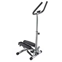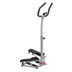
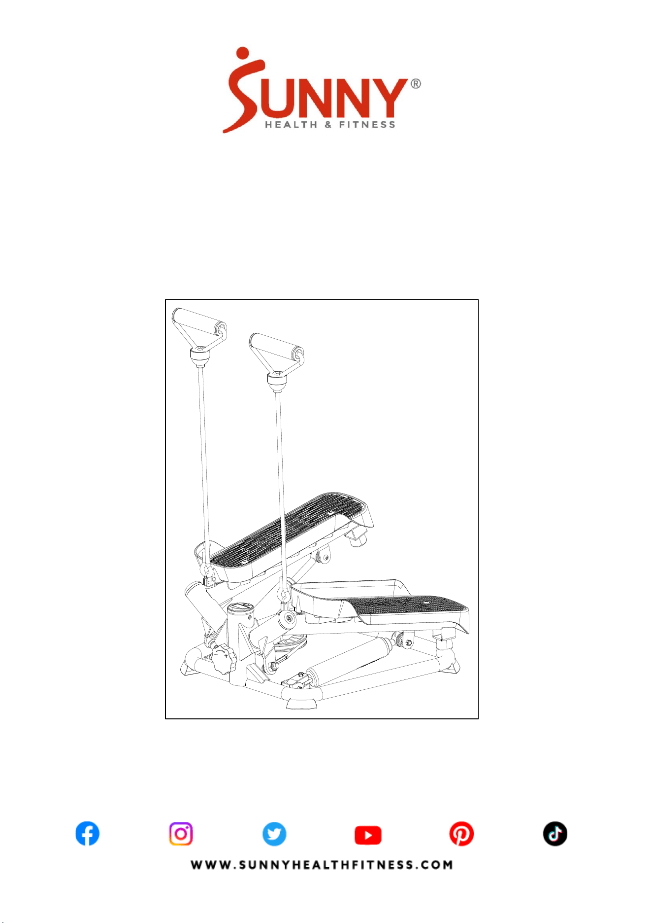
SMART TWIST STEPPER MACHINE
SF-S0979 SMART
USER MANUAL
IMPORTANT! Please retain owner’s manual for maintenance and adjustment instructions. Your
satisfaction is very important to us, PLEASE DO NOT RETURN UNTIL YOU HAVE CONTACTED
US: [email protected] or 1- 877 - 90SUNNY (877-907-8669).

1
IMPORTANT SAFETY INFORMATION
We thank you for choosing our product. To ensure your safety and health, please use this
equipment correctly. It is important to read this entire manual before assembling and using the
equipment. Safe and effective use can only be achieved if the equipment is assembled, maintained,
and used properly. It is your responsibility to ensure that all users of the equipment are informed of
all warnings and precautions.
1. Before starting any exercise program, you should consult your physician to determine if you have
any medical or physical condition that could put your health and safety at risk or prevent you from
using the equipment properly. Your physician’s advice is essential if you are taking medication
that affects your heart rate, blood pressure or cholesterol level.
2. Be aware of your body’s signals. Incorrect or excessive exercise can damage your health. Stop
exercising if you experience any of the following symptoms: pain, tightness in your chest, irregular
heartbeat, shortness of breath, lightheadedness, dizziness, or feelings of nausea. If you do
experience any of these conditions, you should consult your physician before continuing with your
exercise program.
3. Keep children and pets away from the equipment. The equipment is designed for adult use only.
4. Use the equipment on a solid, flat level surface with a protective cover for your floor or carpet. To
ensure safety, the equipment should have at least 2 feet (60 cm) of free space all around it.
5. Ensure that all nuts and bolts are securely tightened before using the equipment. The safety of the
equipment can only be maintained if it is regularly examined for damage and/or wear and tear.
6. Always use the equipment as indicated. If you find any defective components while assembling or
checking the equipment, or if you hear any unusual noises coming from the equipment during
exercise, discontinue use of the equipment immediately and do not use until the problem has
been rectified.
7. Wear suitable clothing while using the equipment. Avoid wearing loose clothing that may
become entangled in the equipment.
8. Do not place fingers or objects into the moving parts of the equipment.
9. The maximum weight capacity of this unit is 350 lbs (160 kgs).
10. The equipment is not suitable for therapeutic use.
11. To avoid bodily injury and/or damage to the product or property, proper lifting and moving are
required.
12. Your product is intended for use in cool and dry conditions. You should avoid storage in extremely
cold, hot or damp areas as this may lead to corrosion and other related problems.
13. This equipment is designed for indoor and home use only; it is not intended for commercial use.
2
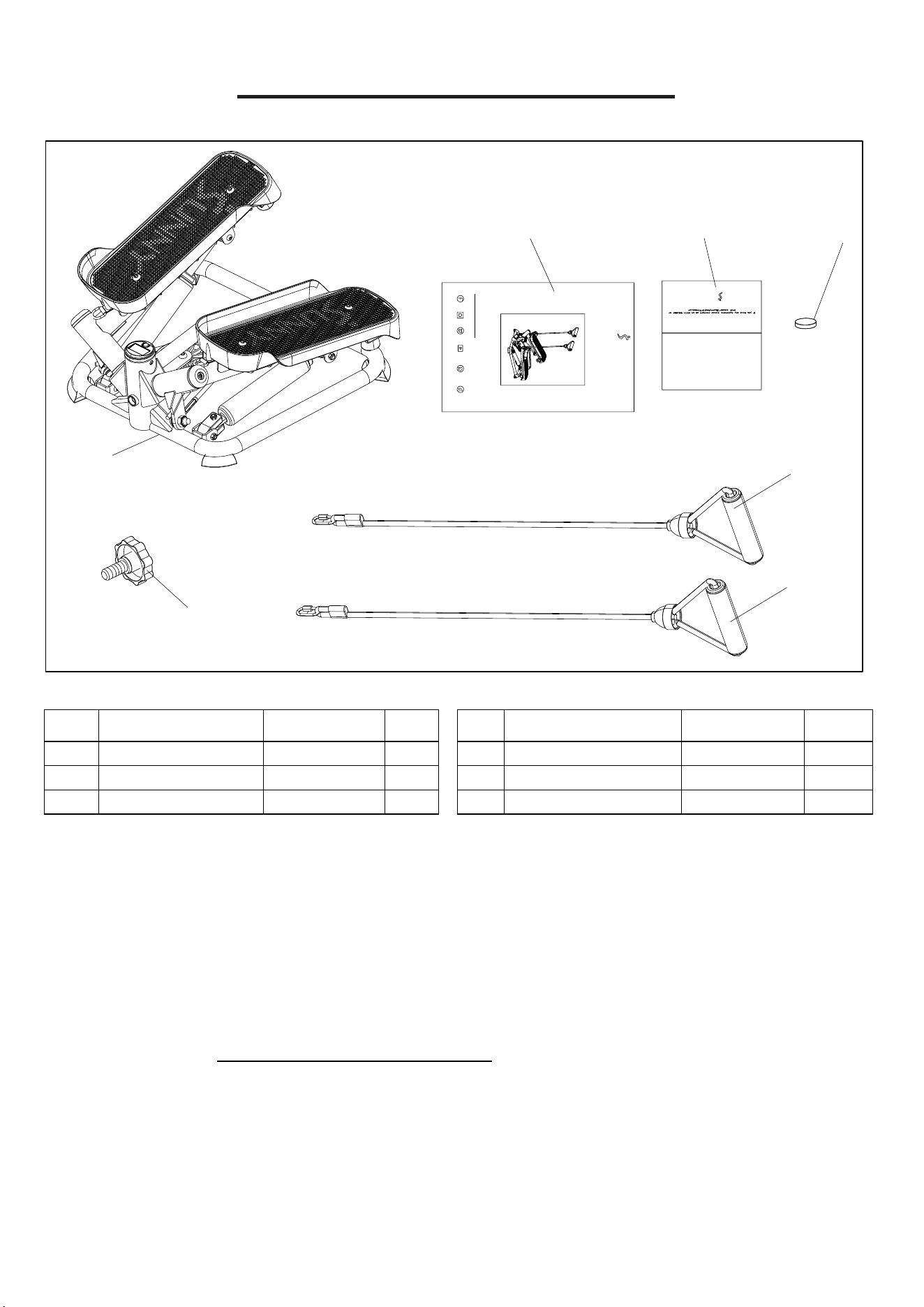
PRE-ASSEMBLY CHECK LIST
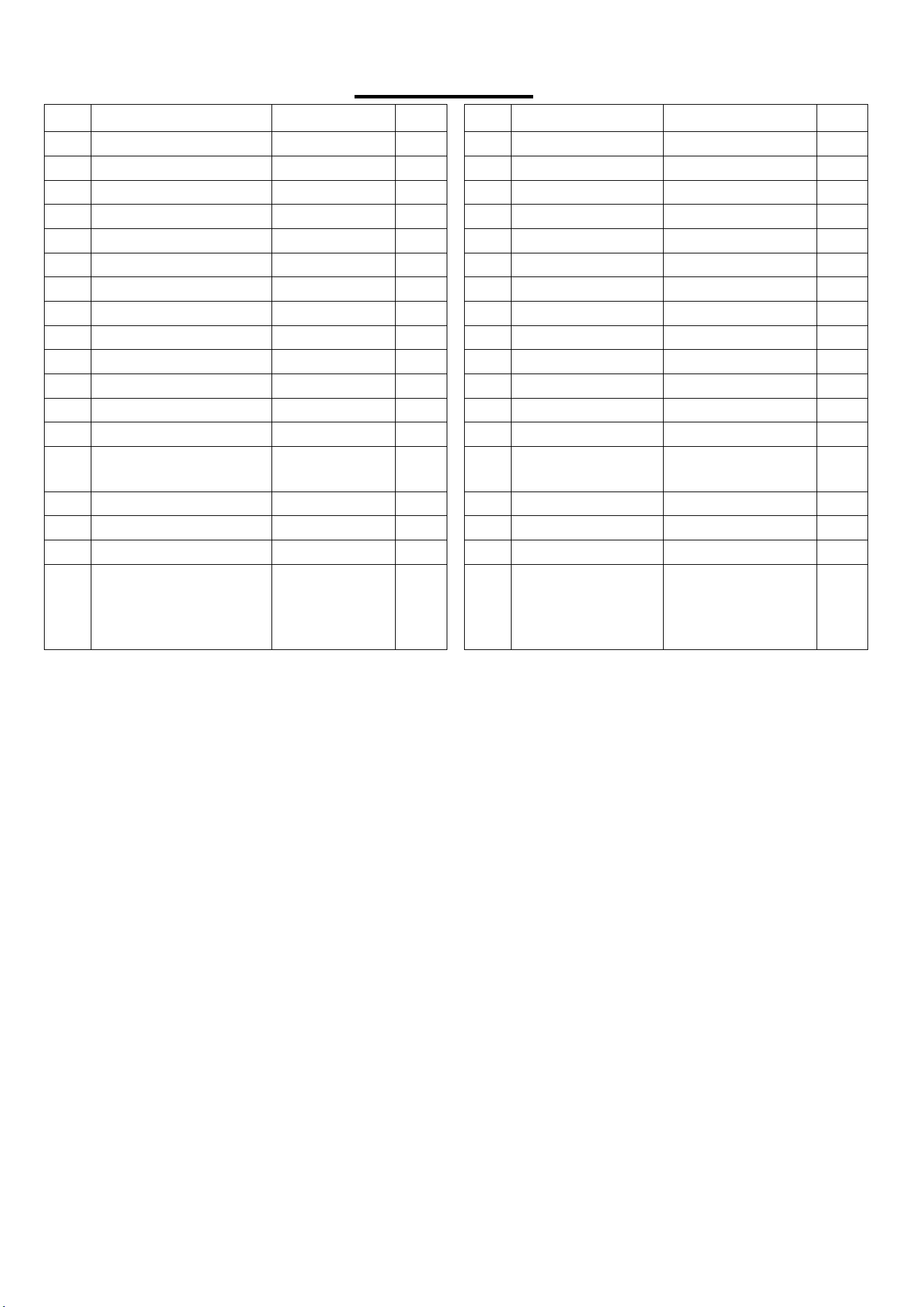
Before you start to assemble, please make sure all parts are included.
No.
Description
Spec.
Qty.
No.
Description
Spec.
Qty.
1
Main Frame
1
A
Manual
1
21
Adjustment Knob
Φ60*M14
1
B
Thank You Card
1
34
Exercise Band
Φ8*640
2
C
Battery
CR2032
1
Ordering Replacement Parts (U.S. and Canadian Customers only)
Please provide the following information in order for us to accurately identify the part(s) needed:
✓ The model number (found on cover of manual)
✓ The product name (found on cover of manual)
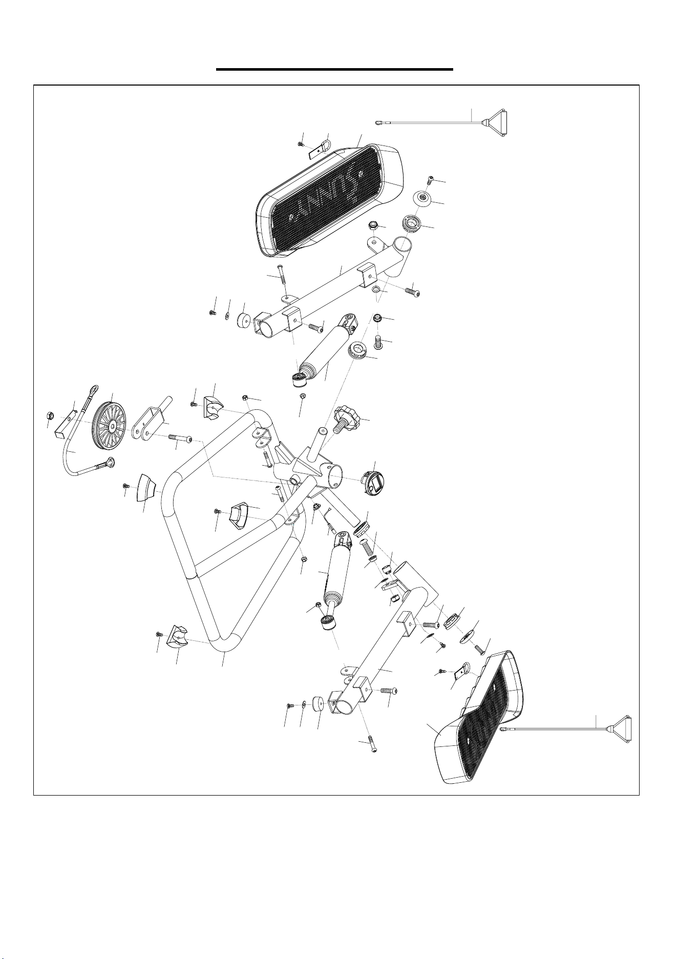
✓ The part number found on the “EXPLODED DIAGRAM” (page 9) and “PARTS LIST” (page 10)
Please contact us at [email protected] or 1- 877 - 90SUNNY (877-907-8669).
A
21
34
34
C
B
THANK
YOU
FOR YOUR PURCHASE
UNNY
H E A L T H &
F L T N E S S
1
UNNY
W W W.S U N N Y H E A L T H F I T N E S S.C O M
IMPORTANT! Please retain owner’s manual for maintenance and adjustment instructions. Your
satisfaction is very important to us, PLEASE DO NOT RETU RN UNTIL YOU HAVE CONTACTED
SMART TWIST STEPPER MACHINE
SF-S0979 SMART
USER MANUAL

3
BATTERY SAFETY WARNING
NOTES:
1) Remove and immediately recycle or dispose of used batteries according to local regulations and
keep away from children. Do NOT dispose of batteries in household trash or incinerate.
2) Even used batteries may cause severe injury or death.
3) Call a local poison control center for treatment information.
4) The compatible battery type CR2032 3V.
5) Non-rechargeable batteries are not to be recharged.
6) Do not force discharge, recharge, disassemble, heat above 50°C/122°F, or incinerate. Doing so
may result in injury due to venting, leakage or explosion, resulting in chemical burns.
7) Ensure the batteries are installed correctly according to polarity (+ and -).
8) Remove and immediately recycle or dispose of batteries from equipment not used for an extended
period of time according to local regulations.
9) Always completely secure the battery compartment. If the battery compartment does not close
securely, stop using the product, remove the batteries, and keep them away from children.
4
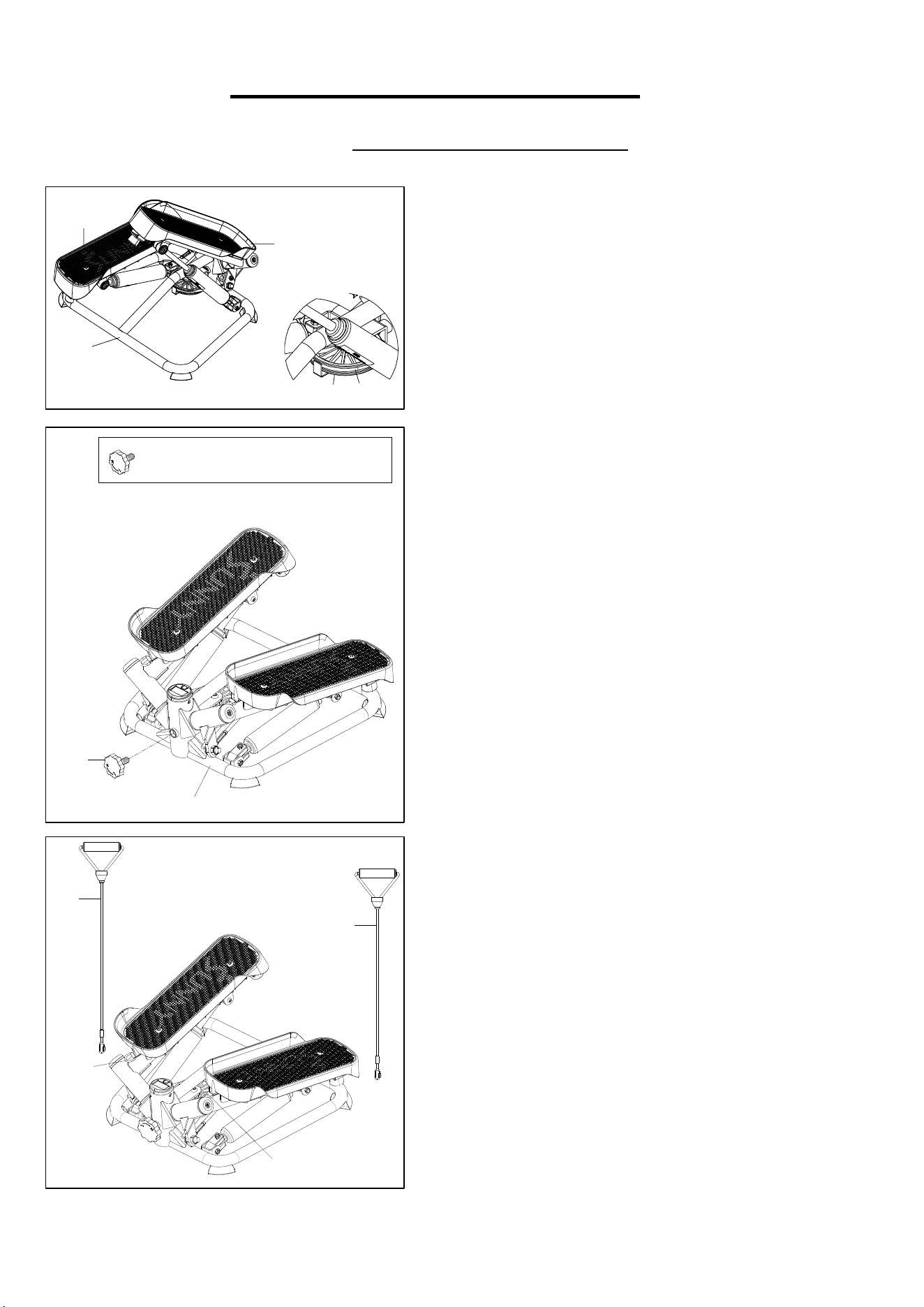
ASSEMBLY INSTRUCTIONS
We value your experience using Sunny Health and Fitness products. For assistance with parts or
(877-907-8669).
13
8
1
22
16
1
21
#21 φ60*52.5*M14*2.0 1PC
15
34
15
34
STEP 2:
Take out the Adjustment Knob (No. 21) from
the manual bag.
Then insert the Adjustment Knob (No. 21) into
the Main Frame (No. 1), and adjust the
tightness of the Adjustment Knob (No. 21) to
the desired position.
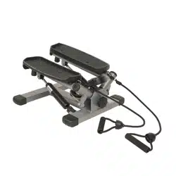
STEP 3:
Connect 2 Exercise Bands (No. 34) to the
Exercise Band Buckles (No. 15) at the front
ofthe left and right pedals as shown in the
picture.
The assembly is complete!
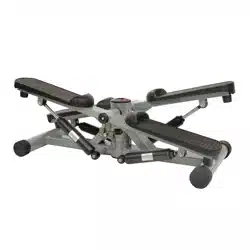
STEP 1:
Remove the Main Frame (No. 1) from the box.
Lift one pedal of Left Pedal or Right Pedal (No.
8 or No. 13) up with your hand and ensure that
the Wire Rope (No. 22) is put in the slot of the
Pulley (No. 16) as shown in the picture.
5
13
8
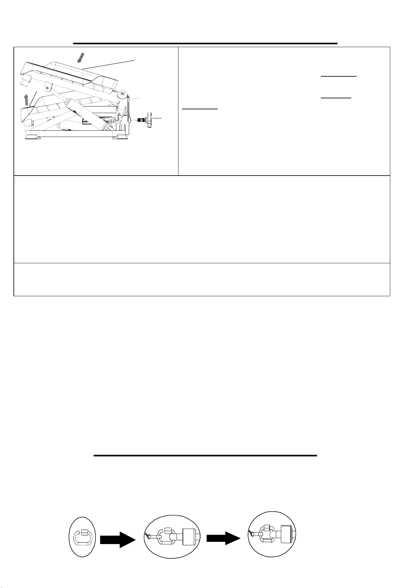
MAINTENANCE & ADJUSTMENT GUIDE
ADJUSTING THE STEPPING HEIGHT
Turn the Adjustment Knob (No. 21) clockwise to
increase the stepping height.
Turn the Adjustment Knob (No. 21) counter-
clockwise to decrease the stepping height.
NOTE: Before turning the adjustment knob, you need
to lift one pedal of the Left or Right Pedals (No. 8 or
No. 13) up and ensure the cable is around the pulley.
If the cable is not properly positioned around the
pulley, it can cause damage to the main frame of the
product or prevent the height from adjusting correctly.
CLEANING
The stepper can be cleaned with a soft, clean, and damp cloth. Do not use abrasives or solvents on
plastic parts. Please wipe your perspiration off the stepper after each use. Be careful not get
excessive moisture on the computer display panel as this might cause electrical hazards or
electronics failure.
Please keep the stepper, especially the computer, out of direct sunlight to prevent screen damage.
Please inspect all assembly bolts and pedals on the stepper for proper tightness every week.
STORAGE
Store the stepper in a clean and dry environment, away from children.
NOTES:
If you are having a hard time balancing on the stepper, please hold onto something for support.
The Hydraulic Cylinder (No. 20) may become excessively hot after prolonged use and may be
dangerous to touch. Allow the Hydraulic Cylinder (No. 20) to cool between uses.
EXERCISE BAND INSTRUCTIONS
1. Unscrew the hook nut located on the exercise band until the hook is open as shown in the
picture below.
2. Attach the exercise band hook onto the exercise band buckle and screw the hook nut closed
until the exercise band buckle is secured with the hook nut.
3. Assembly is done.
21
1
6
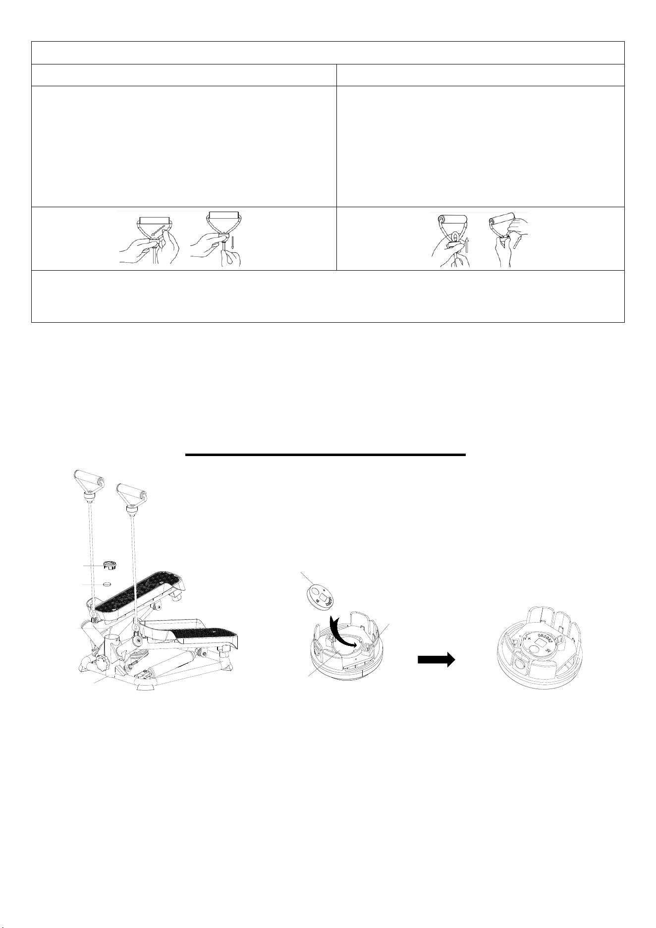
CHANGING THE BATTERY
1. Remove Computer (No. 32) from Main Frame (No. 1) and disconnect the link wire of Sensor
(No. 28) from the Computer (No. 32).
2. Remove the battery from the backside of Computer (No. 32).
3. Please insert the battery diagonally into the backside of Computer (No. 32). Please ensure the
positive (+) side is facing upward. and make sure the battery is under the obstruction as shown
in above diagram.
Note: If the battery is not installed properly, the Computer (No. 32) can’t be turned on.
4. Insert the link wire of Sensor (No. 28) into the wire inserting hole on the back of Computer (No.
32).
5. Insert the Computer (No. 32) into Main Frame (No. 1).
28
32
BATTERY
1
WIRE INSERTING HOLE
BATTERY SEAT
BATTERY
Adjusting the Exercise Band Length
To Lengthen Exercise Band
To Shorten Exercise Band
Push one side of the exercise band down and
then pull the bottom of the exercise band
downward as shown in the picture below.
Repeat this process until the exercise band is at
the desired length.
NOTE: This adjustment decreases the tension on
the exercise bands.
Push the exercise band upward from the
bottom and then pull one side of the top
exercise band up as shown in the picture below.
Repeat this process until the exercise band is at
the desired length.
NOTE: This adjustment increases the tension
on the exercise bands.
NOTE: When lengthening the exercise band, only one side of the exercise band can be pushed
down. If the side that you are trying to push down does not move, try the other side of the exercise
band.

7
EXERCISE COMPUTER
FUNCTION BUTTONS:
MODE: This button lets you to select a function. The computer will be reset by
pressing the MODE button for 3~4 seconds except TOT. CNT (TOTAL
COUNT).
SPECIFICATIONS:
CNT (COUNT) ------------------------------------------------------0~9999 TIMES
TMR (TIME) ---------------------------------------------------------00:00~99:59 MIN
CAL (CALORIES) -------------------------------------------------0~9999 KCAL
TOT. CNT (TOTAL COUNT) ------------------------------------0~9999 TIMES
FUNCTIONS & OPERATIONS:
1. CNT (COUNT):
Automatically accumulates the count of steps taken during exercise. The computer counts 1
step after you step once with each foot.
2. TMR (TIME):
Counts the total time of an exercise from start to finish.
3. CAL (CALORIES):
Counts the number of total calories burned during an exercise from start to finish.
4. TOT. CNT (TOTAL COUNT):
Displays total counts of steps since the battery is installed. To reset TOT. CNT (TOTAL COUNT),
you need to remove the battery and reinsert.
5. S (SCAN):
Press the MODE button until the computer shows the flickering S. SCAN mode will
automatically scan each function in the following order: CNT- TMR- TOT. CNT- CAL.
BATTERY:
1. If you have an inaccurate reading on the computer, please replace the battery immediately.
2. The computer uses one CR2032 battery.
3. The computer is auto-powered. It turns on when exercise begins, and it turns off when no
movement is made between 4 to 5 minutes.
4. All functions will automatically stop calculating when 'STOP' appears in the bottom right corner
of the computer. This occurs when there is no signal for a period of 4 seconds. Once the
exercise begins again, the computer will automatically start recalculating.
8
APP CONNECTION:
Connect Smart Equipment to SunnyFit App:
1. Scan to download SunnyFit from the app store:
2. Ensure that the Bluetooth function is turned on from your mobile device.
3. If this is your first time using the SunnyFit app, follow the in-app instructions to register for
your free SunnyFit account and log in.
4. Begin any workout activity that matches your smart equipment, then follow the onscreen
prompts to search for and connect to your smart equipment.
5. When connected, your stats and records will be displayed at the end of your course/session,
and recorded in your account profile!
Troubleshooting:
⚫ If you are having trouble connecting your smart equipment, visit www.sunnyfit.com/guide or
scan the QR code below:
⚫ If you require additional support, please contact [email protected]
9
EXPLODED DIAGRAM
35
36
1
10
10
15
5
6
7
7
8
9
3
10
10
9
15
6
7
7
11
12
13
14
14
4
16
20
20
21
22
23
23
24
25
25
26
26
27
27
29
30
30
30
30
11
11
11
11
31
31
31
31
27
27
32
17
28
2
33
33
11
5
34
34
24
19
18
10
PARTS LIST
No.
Description
Spec.
Qty.
No.
Description
Spec.
Qty.
1
Main Frame
1
19
Nylon Nut
M8
1
2
Left Foot Bar
1
20
Hydraulic Cylinder
Φ38
2
3
Right Foot Bar
1
21
Adjustment Knob
Φ60*52.5*M14*2.0
1
4
Pulley Fixed Bracket
1
22
Wire Rope
Φ6.5*365
1
5
Cushion
Φ30*20
2
23
Plastic Gasket
Φ16*Φ10.2*1
2
6
Hexagon Bolt
M6*20*S5
2
24
Alloy Wrap
2
7
Hexagon Bolt
M8*20*S5
4
25
Hexagon Bolt
M10*30*21*S5
2
8
Left Pedal
373*151*82
1
26
Nylon Nut
M10
2
9
Cover
2
27
Hexagon Bolt
M6*36*8*S5
4
10
Bushing
Φ38*Φ19.1*12
4
28
Sensor
1
11
Hexagon Bolt
M5*10*S3
6
29
Sensor Holder
Φ17*Φ11*8
1
12
Magnet
Φ17*Φ11*12
1
30
Foot Pad
58.4*33.7*20
4
13
Right Pedal
373*151*82
1
31
Nylon Nut
M6
4
14
Cross Countersunk
Head Tapping Screw
ST4.8*8
2
32
Computer
DSC03609-APP
1
15
Exercise Band Buckle
2
33
Flat Washer
Φ12*Φ5.2*1
2
16
Pulley
Φ100*Φ8.2*20
1
34
Exercise Band
Φ8*640
2
17
Limit Plate
1
35
Magnet Cap
Φ15*3.5
1
18
Hexagon Bolt
M8*40*15*S6
1
36
Cross
Countersunk
Head Tapping
Screw
ST3*8
1
Version:1.1

11