Loading ...
Loading ...
Loading ...
11
ADJUSTMENTS
TO ADJUST THE SANDING ANGLE
Before making any adjustments to the tool, disconnect the machine from the power source.
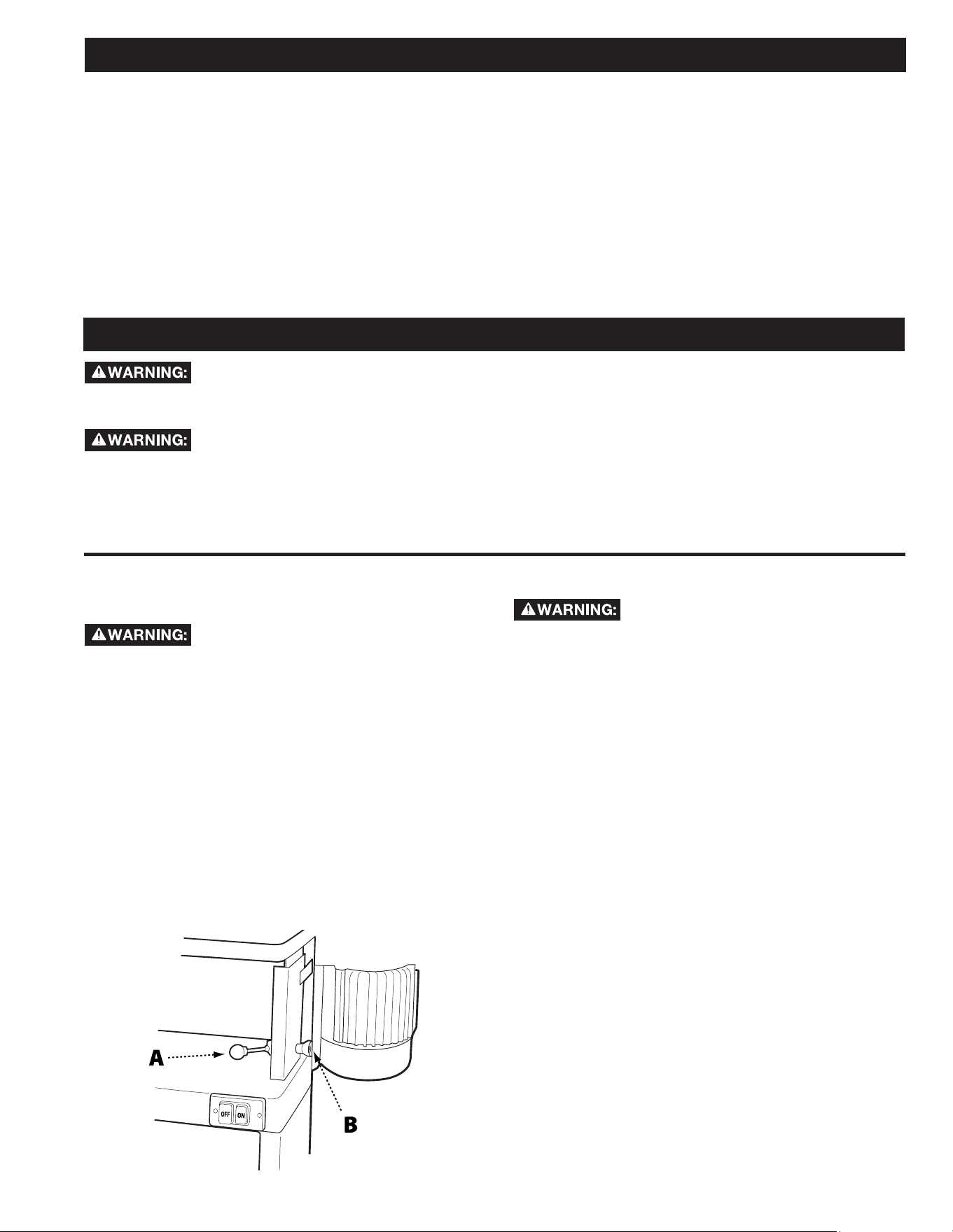
FIGURE 9
INSTALLING THE SANDING FENCE
TOOLS REQUIRED
• None
PARTS
• Sanding Fence
• Two (12mm) Lock Knobs
HARDWARE NEEDED
• T-Nuts (2)
• 5/16 inch Flat Washers (2)
1. Slide the two T-nuts into the slot located on the
sanding table.
2. Position the sanding fence so that one of the t-nuts
is aligned with one of the positioning slots.
3. Place a 5/16 inch flat washer onto a (12mm) lock
knob and thread the lock knob into the t-nut.
4. Reposition the sanding fence so that the other
positioning slot is aligned with second t-nut.
5. Place a 5/16 inch flat washer onto the second
(12mm) lock knob and thread the lock knob into the
second t-nuts.
6. Position the fence to the desired distance from the
belt and securely tighten both lock knobs.
Before making any adjustments to the tool, disconnect the machine from the power source.
1. Loosen the platen locking lever by pulling forward.
2. Move the sanding platen to the desired position. Use
a combination square between the table and sanding
platen to get precise angles.
3. Hold the platen steady and push the platen locking
lever back to the locked position.
TO ADJUST THE TENSION ON
THE PLATEN LOCKING LEVER
Before making any adjustments to the
tool, disconnect the machine from the power source.
1. Loosen the platen locking lever (A) and rotate the
platen into the horizontal (flat) position. Do not lock.
2. Adjust tension on the eccentric block by tightening
the nylon nut (B) with a 14mm wrench. See Figure 9.
Turn the nut in 1/4-turn increments and test locking
handle for proper tension.
3. The platen locking lever is properly tensioned when
it requires positive force to move the eccentric block
from one side to the other.
4. Ensure the platen and motor assembly remains
stationary when the platen locking lever is in the
locked position. Re-adjust as necessary.
TO CHANGE THE SANDING BELT
Before making any adjustments to the
tool, disconnect the machine from the power source.
1. Ensure the sanding platen is locked in the vertical
(upright) position. Reposition if needed. (Refer to
Adjusting the Sanding Angle at the top pf this page).
2. Remove the belt guard by loosening the two lock
knobs and sliding the belt guard to the right.
3. Release tension on the belt by moving the belt
tensioning lever to the Loose position as indicated on
the label on top of the guard.
4. Remove the old belt by working it up and over the
rollers.
5. Fit the new belt onto the sanding platen. Note:
Make sure that direction arrow on belt matches the
direction indicator on the top of the sanding platen.
The edge of the belt should be even with the edge of
the rollers.
6. Re-tension the belt by moving the belt tensioning
lever to the Tight position.
7. Rotate the belt by hand in the direction indicated by
the arrow to ensure proper belt tracking. Note: Belts
stretch with wear. When replacing a belt, you may
have to adjust tracking. See Belt Tracking Adjustment
on page 12.
8. Reinstall the belt guard and tighten the lock handles.
Loading ...
Loading ...
Loading ...