
Loading ...
Loading ...
Loading ...
10
INSTALLING THE CONTOUR SANDING TABLE
TOOLS REQUIRED
• 12mm socket wrench
PARTS
• Contour Sanding Table
• Mounting Pole
• Mounting Bracket
• 20mm Lock Knob
HARDWARE NEEDED
• 10 24 x 3/4 Socket Head Cap Screws (2)
• 12mm Hex Cap Bolt
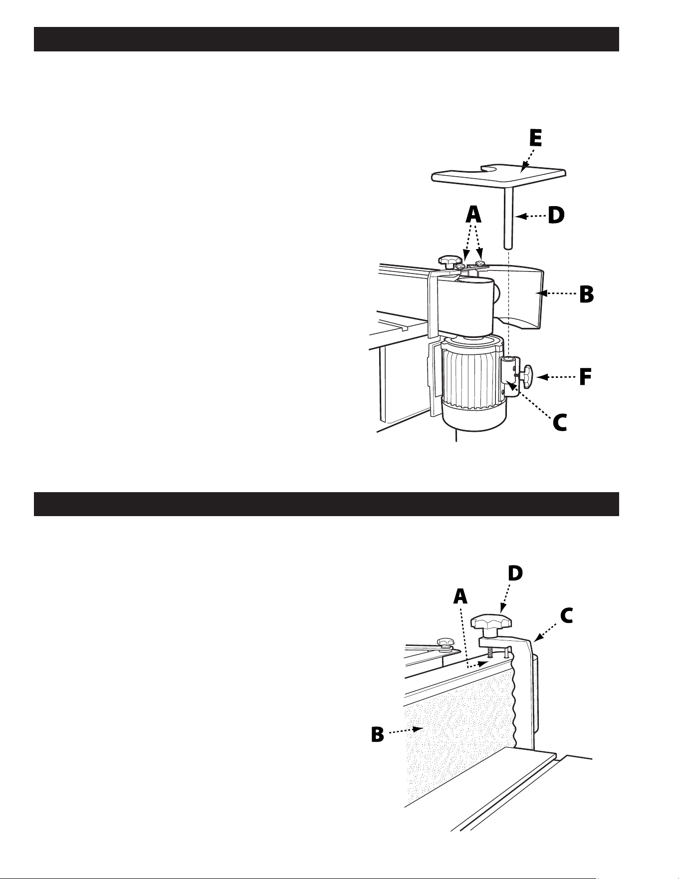
1. Loosen the lock knobs (A) on the drum guard (B)
and rotate the drum guard back and out of the way.
Retighten the lock knobs.
2. Attach the mounting bracket (C) to the side of the
motor housing and secure using the two 10 24 x
3/4 socket head cap screws, as shown in Figure 7.
The longer end of the mounted bracket should be at
the bottom.
3. Insert the mounting pole (D) into the contour sanding
table (E) and secure with 12mm hex cap bolt and
lock nut.
4. Insert the mounting pole/table assembly into the
mounting bracket. Ensure there is clearance on all
sides between the sanding belt and the contour
sanding table.
5. Secure the mounting pole/table assembly to the
mounting bracket using the (20mm) lock knob (F).
Important: When the contour sanding table is not in
use, the drum guard/dust port should always be in the
closed position so the drive drum is not in view.
FIGURE 8
FIGURE 7
INSTALLING THE WORKPIECE SUPPORT
TOOLS REQUIRED
• None
PARTS
• Workpiece Support
• (35mm) Lock Knob
HARDWARE NEEDED
• None
1. Locate the two holes (A) on the right hand side of
the top of the sanding platen. See Figure 8.
2. Insert the pin of the workpiece support (C) into the
hole closest to the front.
3. Secure the workpiece support to the sanding platen
by screwing the (35mm) lock knob (D) into the
tapped hole closest to the rear.
4. Ensure the workpiece support is as close to the
sanding belt (B) as possible without touching it.
5. Tighten the lock knob.
Loading ...
Loading ...
Loading ...