Loading ...
Loading ...
Loading ...
23
EE
EN
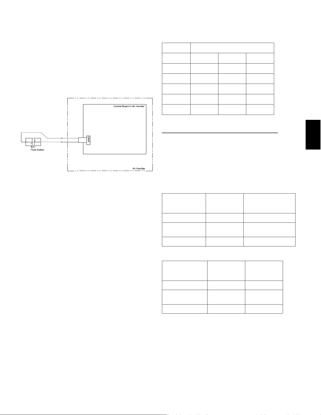
13.3.Condensateoverowsafetyswitchconnection
(CN4F)
The circuit board is equipped with a connection to attach a
condensatesafetyoatswitch.Theswitchshouldbeanormally
closed low voltage rated switch. The switch should be installed in a
location that it can sense a drain blockage causing a rise in water
level. This resulting rise in level will cause it to open. The switch
location is to be determined by the installing contractor. When the
switch opens, it will cause the LEV to close, stopping the cooling
operation. The fan will continue to run and a fault code will be shown
at the controller. Correcting the problem and closing the switch will
be required before normal operation can resume.
See installation below:
13.4. Changing blower external static pressure
The air handler is equipped with an adjustable static pressure
setting. The available settings are shown in the table below.
Model Available ESP [in. WG]
PVA-A12 0.30 0.50 0.80
PVA-A18 0.30 0.50 0.80
PVA-A24 0.30 0.50 0.80
PVA-A30 0.30 0.50 0.80
PVA-A36 0.30 0.50 0.80
PVA-A42 0.30 0.50 0.80*
*PVA-A42inDownowExternalStaticpressure:0.70
The air handler will be set to 0.50 ESP from the factory.
The air handler’s static pressure can be changed through the mode/
function settings in the controller. Please refer to the installation
manual for the controller on how to change this option. Depending
on the controller used, the mode/function will be either 08 for mode
(PAR-31 & Simple MA) or 108 for function (MHK1). Please notice
therearedierentsettingswheninstallingtheairhandlerinthe
downowposition.
Vertical, Horizontal Left, Horizontal Right External Static
Pressure Setting
External Static
Pressure
Setting No. of
Mode/Function
08/108
Setting No. of Mode/
Function 10/110
(Factory Setting)
0.3 in. WG [75Pa] 1 1
0.5 in. WG [125Pa]
(Factory Setting)
2 1
0.8 in. WG [200Pa] 3 1
DownowExternalStaticPressureSetting
External Static
Pressure
Setting No. of
Mode/Function
08/108
Setting No. of
Mode/Function
10/110
0.3 in. WG [75Pa] 1 2
0.5 in. WG [125Pa]
(Factory Setting)
2 2
0.8 in. WG [200Pa]* 3 2
*PVA-A42inDownowExternalStaticpressure:0.70
Locate the CN4F connector on the
control board. Carefully remove the
connector with the jumper from the
board. Cut the jumper on the CN4F
connector and wire a normally
closedsafetyoatswitchacross
the wires. Carefully reinstall the
connector back on the board.
When the Normally Closed Float
Switch opens, the Indoor unit will
turno.
Loading ...
Loading ...
Loading ...