Loading ...
Loading ...
Loading ...
22
EE
EN
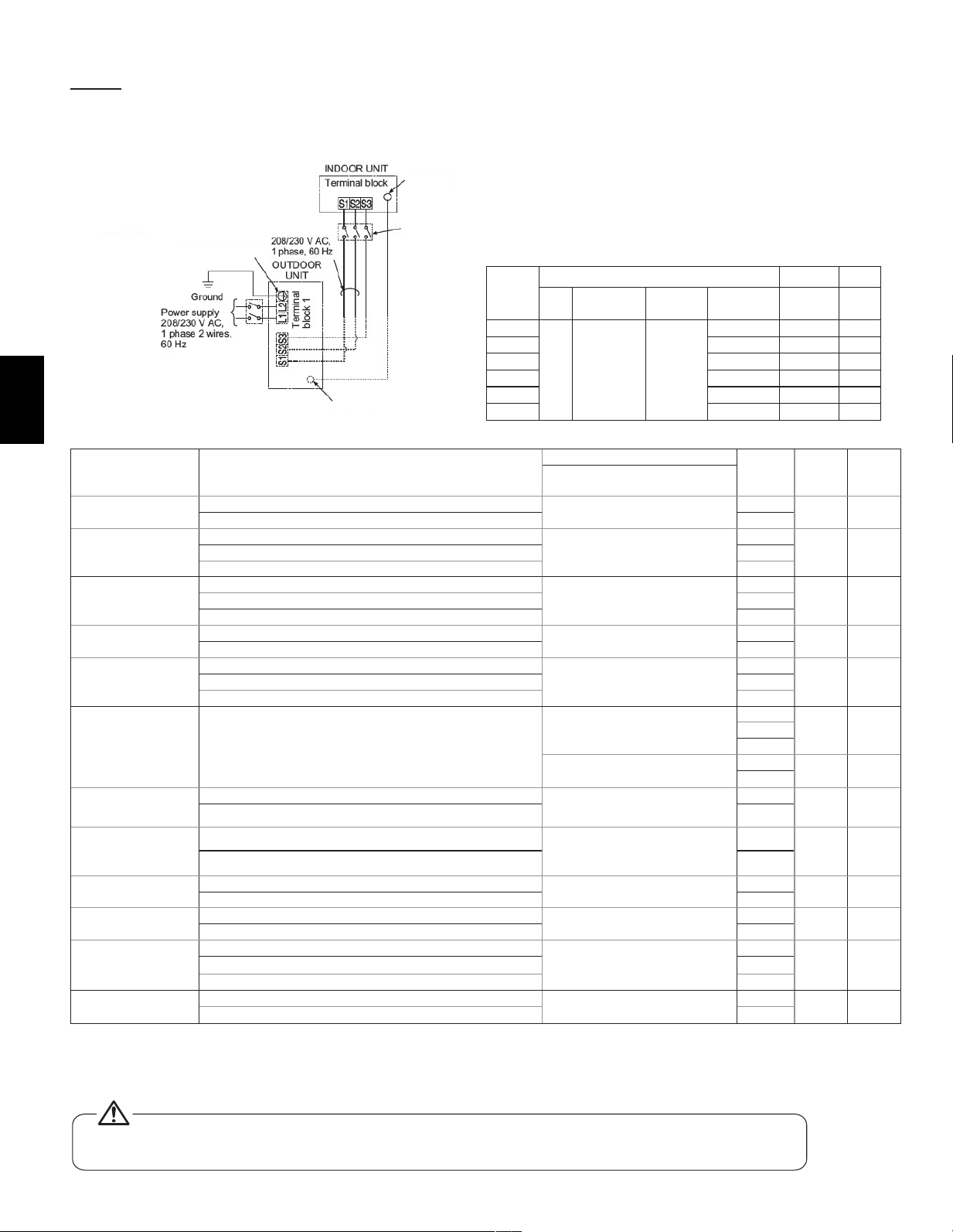
13.2. Connecting line voltage
Makesurepowersupplyiso�.
The unit should be installed by a licensed contractor/
electrician. If required by applicable national, state and local
codes; a disconnect switch will need to be installed when the
indoor unit is powered from the outdoor unit.
Function Table
Mode Settings
Mode (function) No.
Setting
no.
Initial
setting
Check
Wired remote controller
(RF thermostat)
Power failure auto
restart
Not available
01
(101)
1
1
Available 2
Indoor temperature
detecting
Indoor unit operating average
02
( - )
1
1Set by indoor unit’s remote controller 2
Remote controller’s internal sensor 3
LOSSNAY
connectivity
Not Supported
03
(103)
1
1
Supported (indoor unit is not equipped with outdoor air intake 2
Supported (indoor unit is equipped with outdoor air intake 3
Power voltage
240V (230V)
04
(104)
1
1
220V (208V) 2
Filter sign
100 Hr
07
(107)
1
32500 Hr 2
“No�ltersignindicator” 3
External static
pressure
See Section 13.4 of the installation manual
08
(108)
1
22
3
10
(110)
1
1
2
Humidi�ercontrol
Heat operation & Thermo ON
16
(116)
1
1
Heat operation 2
Humidi�er
Humidi�ernotpresent
13
(113)
1
1
Humidi�erpresent 2
Heater Control
Heater Not Present
11
(111)
1
1
Heater Present *1 2
Heater control during
defrost and error
Disable heater during Defrost and Error
23
(123)
1
1
Enable heater and fan during Defrost and Error *2 2
Fan speed thermo
oheating
Extra low
25
(125)
1
1Stop 2
RC setting 3
Fan speed thermo
ocooling
RC setting 27
(127)
1
1
Stop 2
*1 While the heater is on, the fan will operate at high speed regardless of the fan setting on the remote controller
*2 Heater will not operate during all error modes. Heater will only operate during a communication error between indoor unit and outdoor unit
Note:WhenCN4YisusedthefanisowhenCN24isenergizedwhichisonlyforusewithsupplementalheatthatisnotintheduct.
- Please see section 13.4. of the installation manual for external static pressure settings.
* If a heater is installed in the duct, do not use Panel heater connector. By doing so, the fan will turn off
when the heater is on, which may result in fire.
NOTE: If the air handler will be installed with electric heat
package do not power the electric heat from the outdoor unit.
All wiring must conform to National and Local codes
1. Remove the desire knockout on the air handler.
2. Attach a conduit pipe connector to the air handler and route the
wiring as shown in the above diagram. Ensure conduit connection
hole is air tight and add a sealant if necessary.
3. Firmly tighten all of the terminal screws. After tightening, verify that
the wires are tightly fastened.
Electrical Characteristics
Symbols : MCA : Max. Circuit Amps ( = 1.25 × FLA) FLA : Full Load Amps
IFM : Indoor Fan Motor Output : Fan motor rated output
Model
Indoor Unit
Hz Volts
Voltage
Range
MCA
(A)
Output
(kW)
FLA
(A)
A12
60 208/230V
188 to
253V
3.00/3.00 0.121 2.4
A18 3.00/3.00 0.121 2.4
A24 4.13/4.13 0.244 3.3
A30 4.13/4.13 0.244 3.3
A36 5.5/5.5 0.430 4.4
A42 5.63/5.63 0.430 4.5
Remark:
* Use a ring tongue terminal in
order to connect a ground wire
to terminal.
Grounding Terminal*
Grounding Terminal*
Grounding
terminal*
Disconnect
switch
Loading ...
Loading ...
Loading ...