Air-Conditioners
PVA-A12, 18, 24, 30, 36, 42 AA7
INSTALLATION MANUAL
For safe and correct use, please read this installation manual thoroughly before installing the air-conditioner unit.
FOR INSTALLER
P-SERIES
MANUEL D'INSTALLATION
Veuillez lire le manuel d’installation en entier avant d’installer ce climatiseur pour éviter tout accident et vous
assurer d’une utilisation correcte.
POUR L’INSTALLATEUR
English
Français

2
EE
EN
Contents
Contents .....................................................................................2
1. Dimensions .............................................................................3
2. Inspect shipment ....................................................................4
3. Safety precautions ..................................................................4
3.1. Before installation and electric work ..............................4
3.2. Precautions for devices that use R410A refrigerant ......5
3.3. Before getting started ....................................................5
3.4. Before getting installed (moved)-electrical work ............5
3.5. Before starting the test run ............................................6
4. Indoor unit accessories...........................................................6
5. Selecting an installation site ...................................................6
6. Combining indoor units with outdoor units..............................6
7. Installing the unit.....................................................................7
8. Duct connection ......................................................................7
9. Mount positions ......................................................................8
9.1. Vertical installations .......................................................8
9.2. Horizontal right installations ...........................................9
9.3. Horizontal left installations ...........................................10
9.4.Downowinstallations .................................................14
10.Air�lter................................................................................16
11. Refrigerant piping work .......................................................17
11.1. Insulation ....................................................................18
11.2. Piping size ..................................................................18
12. Drain connections ...............................................................19
13. Electrical wiring...................................................................20
13.1. Remote controllers .....................................................21
13.2. Connecting line voltage, Function Table ....................22
13.3.Condensateoverowsafetyswitchconnection
(CN4F) ...................................................................23
13.4. Changing blower external static pressure ..................23
13.5. ERV (energy recovery ventilation) .............................24
13.6.Humidi�er ...................................................................25
14. Test run ...............................................................................26
14.1. Before test run ...........................................................26
14.2. Test run ......................................................................26
14.3. Self-check ..................................................................26
14.4. AUTO RESTART FUNCTION ....................................28
3
EE
EN
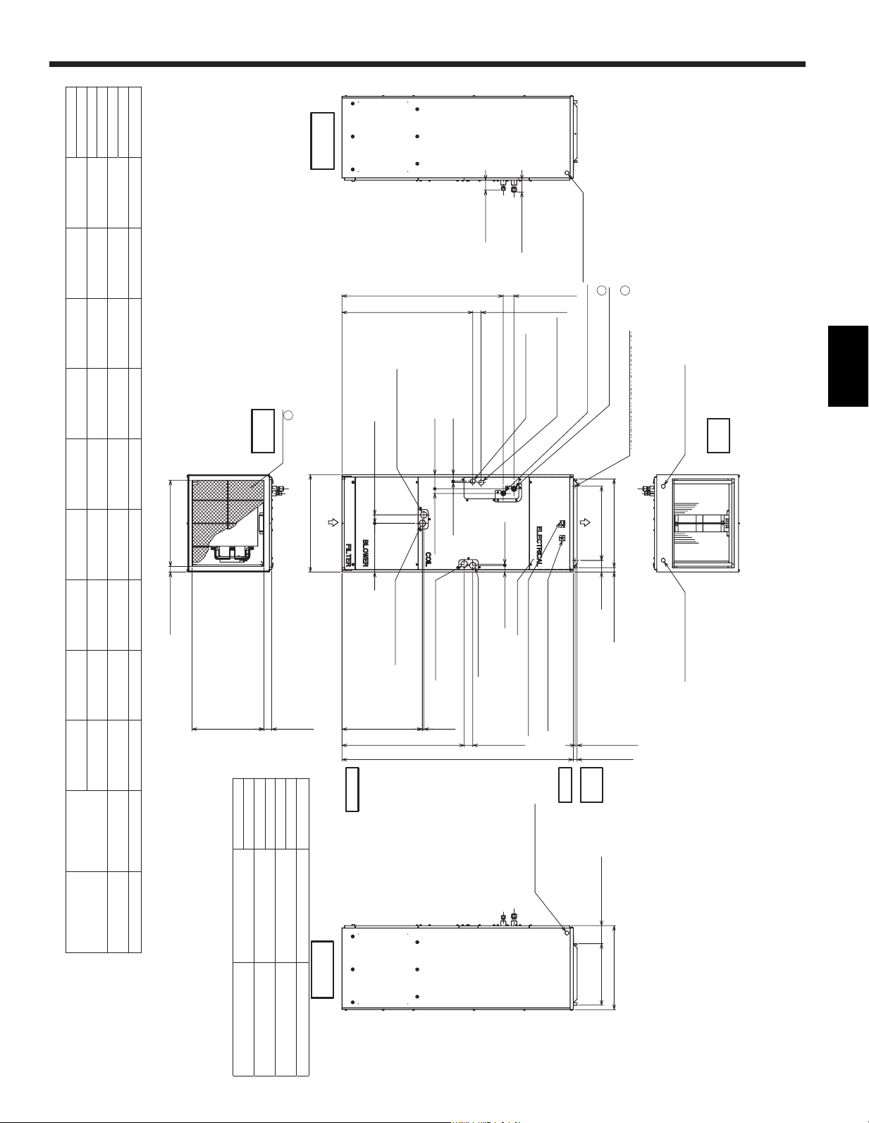
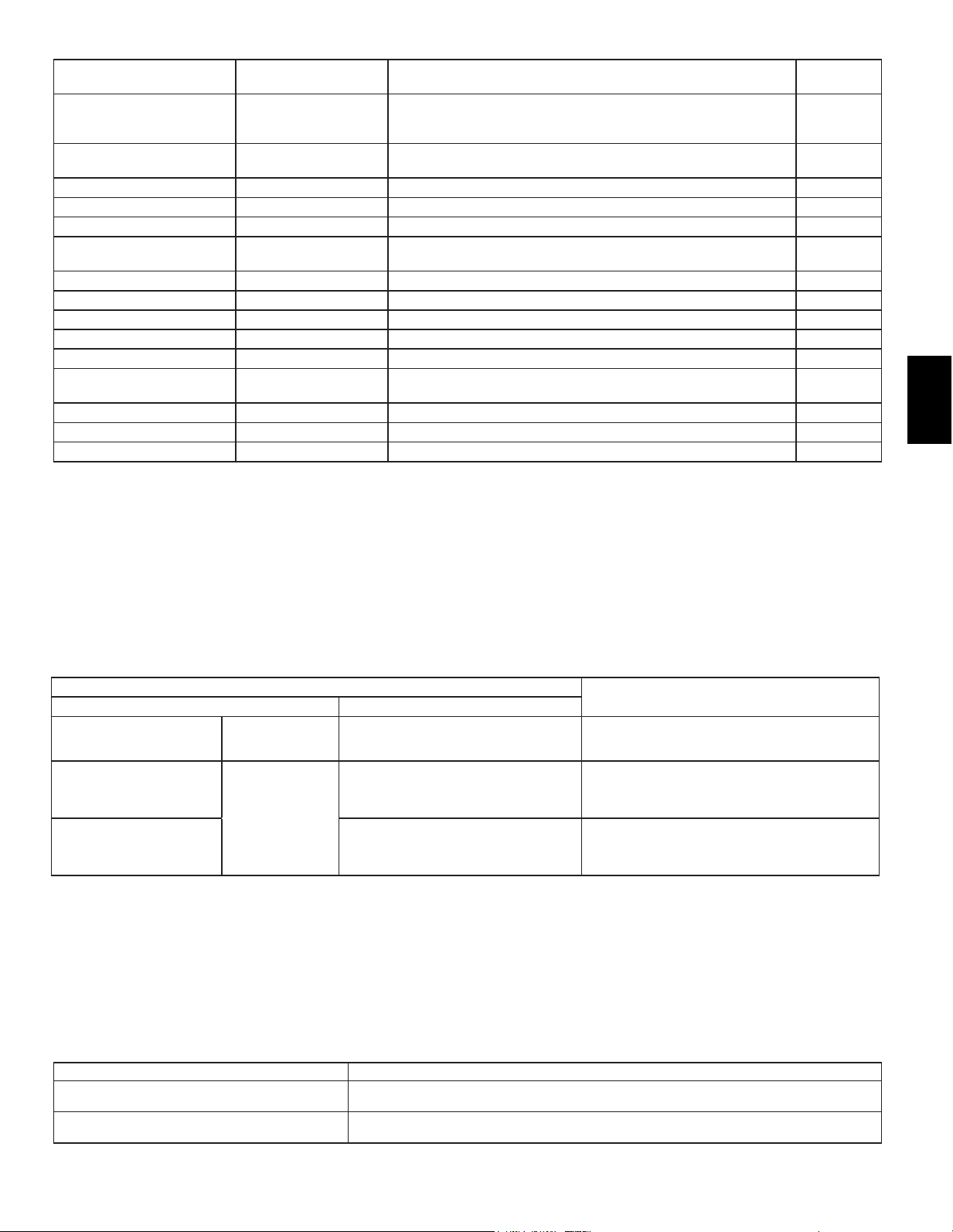
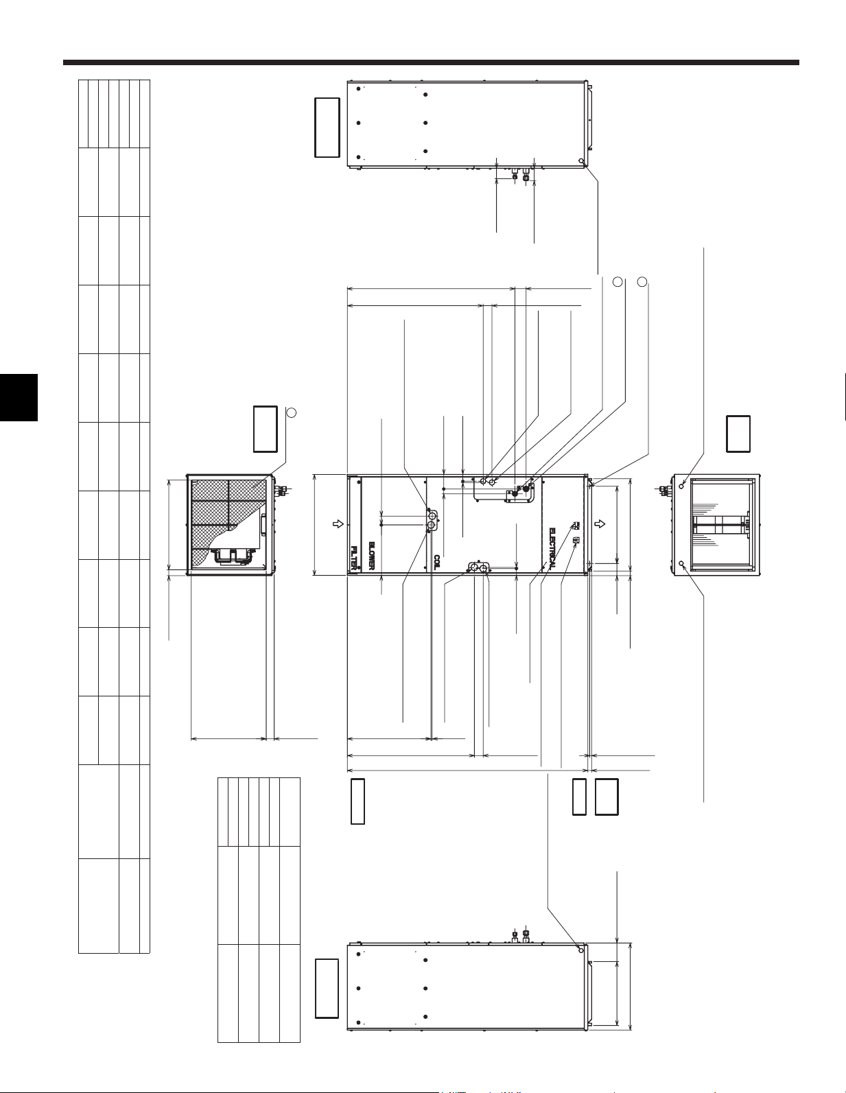
1. Dimensions
Model
Nominal Filter size Duct Connection
PVA-A30AA4
508X508X25.4 477X402
J
77.8(3-1/8)
66(2-5/8)
36.8(1-1/2)
43(1-3/4) 8(3/8)
92(3-5/8) 30(1-3/16)
43(1-3/4)
8(3/8)
55(2-3/16)
548(21-5/8)
117.4 (4-5/8)
402(15-7/8)
B(Duct)
28.8(1-3/16)
76(3)
C
A
D
525.5(20-3/4)50.8(2)470(18-9/16)
H
55(2-3/16)
G
70(2-13/16)
8(3/8)
F
55(2-3/16)
E
24(15/16)
13.2(9/16)
Control box
Air filter
Air outlet
Air inlet
(Duct)
Refrigerant piping
brazing connection(gas)
Refrigerant piping
brazing connection(liquid)
Primary drain pipe
(Gravity drain)
ø19.05(3/4) 3/4"FPT
Secondary drain pipe
(Emergency draining)
ø19.05(3/4) 3/4"FPT
Primary drain pipe
(Gravity drain)
ø19.05(3/4) 3/4"FPT
(Horizontal left)
(Horizontal Right)
Secondary drain pipe
(Emergency draining)
ø19.05(3/4) 3/4"FPT
Primary drain pipe
(Gravity drain)
ø19.05(3/4) 3/4"FPT
Secondary drain pipe
(Emergency draining)
ø19.05(3/4) 3/4"FPT
Terminal block
(Indoor / Outdoor unit connection)
Terminal block
(Remote controller transmission)
2-ø4.6 Burring Holes
for electric heat installation
ø26 Knockout Hole
(Remote controller transmission)
ø26 Knockout Hole
ø26 Knockout Hole
ø26 Knockout Hole
(Indoor / Outdoor unit connection)
(Indoor /Outdoor
unit connection)
(Remote controller transmission)
Note 1.Keep the service space for maintenance at the front.
Unit:mm(in.)
Top
Top
view
Front
Bottom
Bottom
view
view
Left side
view
Right side
view
3
3
2
1
Unit: mm (in.)
Model A B C D E F G H J
�
Gas Pipe
Liquid Pipe
PVA-A12AA7
432 (17) 376 (14-13/16) 281 (11-1/8) 224 (8-7/8) 1275 (50-1/4) 680 (26-13/16) 823 (32-7/16) 735.5 (29) 360 (14-3/16) Φ12.7(1/2) Φ6.35(1/4)
PVA-A18AA7
PVA-A24AA7
534 (21) 477 (18-13/16) 382.6 (15-1/8) 266.5 (10-1/2) 1378 (54-1/4) 737 (29-1/16) 953.5 (37-9/16) 792 (31-3/16) 461 (18-3/16)
Φ15.88(5/8) Φ9.52(3/8)
PVA-A30AA7
PVA-A36AA7
635 (25) 579 (22-13/16) 484.6 (19-1/8) 317.5 (12-1/2) 1511 (59-1/2) 798.5 (31-7/16) 1053 (41-1/2) 853.5 (33-5/8) 563 (22-3/16)
PVA-A42AA7
Ref rigerant piping
are connection(gas)
for elect ric heat installation
1
Ref rigerant piping
are connection(liquid)
2
Model
Nominal Filter Size
Duct Connection
PVA-A12AA7 508 x 406.4 x 25.4
(20 x 16 x 1)
376 x 402
(14-13/16 x 15-7/8)
PVA-A18AA7
PVA-A24AA7 508 x 508 x 25.4
(20 x 20 x 1)
477 x 402
(18-13/16 x 15-7/8)
PVA-A30AA7
PVA-A36AA7 508 x 609.6 x 25.4
(20 x 24 x 1)
579 x 402
(22-13/16 x 15-7/8)
PVA-A42AA7
4
EE
EN
3.1. Before installation and electric work
Before installing the unit, make sure you read all the “Safety
precautions”.
The “Safety precautions” provide very important points
regarding safety. Make sure you follow them.
Symbols used in the text
Warning:
Describes precautions that should be observed to prevent
danger of injury or death to the user
Caution:
Describes precautions that should be observed to prevent
damage to the unit
Warning:
Carefullyreadthelabelsaxedtothemainunit.
Warning:
• The unit must be installed by an authorized Dealer or
properly trained technician.
− Improper installation by the user may result in water
leakage,electricshock,or�re.
• Install the air unit in a place that can withstand its
weight.
− Inadequate strength may cause the unit to fall down,
resulting in injuries.
• Usethespeci�edcablesforwiring.Makethe
connections securely so that the outside force of the
cable is not applied to the terminals.
− Inadequate connection and fastening may generate heat
andcausea�re.Providestrainrelieftowiring.
• Prepare for typhoons, hurricanes, earthquakes etc. and
installtheunitatthespeci�edplace.
− Improper installation may cause the unit to topple and
result in injury.
• Never repair the unit. If the air conditioner must be
repaired, consult the dealer.
− If the unit is repaired improperly, water leakage, electric
shock,or�remayresult.
• Donotouchtheheatexchanger�ns.
− Improper handling may result in injury.
• When handling the product, always wear protective
equipment.
− EG: Gloves, full arm protection, and safety glasses.
− Improper handling may result in injury.
• Install the air conditioner according to this Installation
Manual.
− If the unit is installed improperly, water leakage, electric
shock,or�remayresult.
• Have all electric work done by a licensed electrician
according the “National Electrical code and local
Electrical codes” and “Interior Wire Regulations” and
the instructions given in this manual and always use a
special circuit.
− If the power source capacity is inadequate or electric work
isperformedimproperly,electricshockand�remayresult.
• Keep the electric parts away from water (washing water
etc.).
− Itmightresultinelectricshock,catching�reorsmoke
.
• When cleaning the Heat Exchanger and Drain Pan,
ensure the Control Box, Motor and LEV remain dry,
water proof covering.
• When installing and moving the air conditioner to
anothersite,donotchargeitwitharefrigerantdierent
fromtherefrigerantspeci�edontheunit.
− Ifadierentrefrigerantorairismixedwiththeoriginal
refrigerant, the refrigerant cycle may malfunction and the
unit may be damaged.
• When moving and reinstalling the air conditioner,
consult the dealer or an authorized technician.
− If the air conditioner is installed improperly, water leakage,
electricshock,or�remayresult.
• Do not reconstruct or change the settings of the
protection devices.
− If the pressure switch, thermal switch, or other protection
devices are shorted and operated forcibly, or parts other
thanthosespeci�edbyMitsubishiElectricareused,�reor
explosion may result.
• To dispose of this product, consult your dealer.
• Do not use a leak detection additive.
• Alwaysuseanaircleaner,humidi�er,electricheater,
andotheraccessoriesspeci�edbyMitsubishiElectric.
− Ask an authorized technician to install the accessories.
Improper installation by the user may result in water
leakage,electricshock,or�re.
• If refrigerant gas leaks during installation work,
ventilate the room.
− Iftherefrigerantgascomesintocontactwithaame,
poisonous gases will be released.
• Securely install the outdoor unit terminal cover (panel).
− If the terminal cover (panel) is not installed properly, dust
orwatermayentertheoutdoorunitand�reorelectric
shock may result.
• If the air conditioner is installed in a small room,
measures must be taken to prevent the refrigerant
concentration from exceeding the safety limit even if
the refrigerant should leak.
− Consult the dealer regarding the appropriate measures to
prevent the safety limit from being exceeded. Should the
refrigerant leak and cause the safety limit to be exceeded,
hazards due to lack of oxygen in the room could result.
3. Safety precautions
2. Inspect shipment
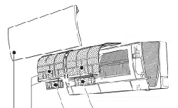
These air handlers are completely factory assembled,
and all components are performance tested. Each
unit consists of a blower assembly, refrigerant coil
and controls in an insulated, galvanized steel factory
enclosure. Knockouts are provided for electrical
wiringentrance.Checktheunitratingplatetocon�rm
speci�cationsareasordered.Uponreceiptofequipment,
carefully inspect it for possible damage. Take special
care to examine the unit if the carton is damaged. If
damage is found, it should be noted on the carrier’s
freightbill.Damageclaimsshouldbe�ledwiththecarrier
immediately.Claimsofshortagesshouldbe�ledwiththe
seller within 5 days.
5
EE
EN
• After completing installation work, make sure that
refrigerant gas is notleaking.
− If the refrigerant gas leaks and is exposed to a fan heater,
stove, oven, or other heat source, it may generate noxious
gases.
• Children should not be allowed around the air
conditioning equipment
• The installer and system specialist shall ensure there
is no refrigerant leakage according to local regulations
and standards.
• Pay special attention to the location the unit is installed
in. Refrigerant is heavier than air so locations such
as basements or crawlspaces where refrigerant can
accumulate can become dangerous.
• The appliance is intended for use by persons (including
children) with reduced physical, sensory or mental
capabilities, or lack of experience and knowledge,
unless they have been given supervision or instruction
concerning use of the appliance by a person
responsible for their safety.
• If the supply cord is damaged, it must be replaced by
themanufacturer,itsserviceagentorsimilarlyquali�ed
persons in order to avoid a hazard.
• Do not use refrigerant other than the type indicated
in the manuals provided with the unit and on the
nameplate.
− Doing so may cause the unit or pipes to burst, or result in
explosionof�reduringuse,duringrepair,oratthetimeof
disposal of the unit.
− It may also be in violation of applicable laws.
− MITSUBISHI ELECTRIC CORPORATION cannot be held
responsible for malfunctions or accidents resulting for the
use of the wrong type of refrigerant.
3.2. Precautions for devices that use R410A refriger-
ant
Caution:
• Do not use the existing refrigerant piping.
−
The old refrigerant and refrigeration oil in the existing
piping contains a large amount of chlorine which may
cause the refrigerator oil of the new unit to deteriorate.
• Use refrigerant piping made of C1220 (Cu-DHP)
phosphorusdeoxidizedcopperasspeci�edintheJIS
H3300 “Copper and copper alloy seamless pipes and
tubes”. In addition, be sure that the inner and outer
surfaces of the pipes are clean and free of hazardous
sulphur, oxides, dust/dirt, shaving particles, oils,
moisture, or any other contaminants.
− Contaminants on the inside of the refrigerant piping may
cause the refrigerant residual oil to deteriorate
• Store the piping to be used during installation indoors
and keep both ends of the piping sealed until just
before brazing. (Store elbows and other joints in a
plastic bag.)
− If dust, dirt, or water enters the refrigerant cycle,
deterioration of the oil and compressor trouble may result.
• Useliquidrefrigerantto�llthesystem.
− If gas refrigerant is used to seal the system, the
composition of the refrigerant in the cylinder will change
and performance may drop.
• Do not use a refrigerant other than R410A.
− If another refrigerant is used, the chlorine in the refrigerant
may cause the refrigerator oil to deteriorate.
• Useavacuumpumpwithareverseowcheckvalve.
− Thevacuumpumpoilmayowbackintotherefrigerant
cycle and cause the refrigerator oil to deteriorate.
• Do not use the following tools that are used with
conventional refrigerants.
− (Gauge manifold, charge hose, gas leak detector, reverse
owcheckvalve,refrigerantchargebase,vacuumgauge,
refrigerant recovery equipment).
− If the conventional refrigerant and refrigeration oil are
mixed in the R410A, the refrigerant may deteriorate.
− If water is mixed in the R410A, the refrigeration oil may
deteriorate.
− Since R410A does not contain any chlorine, gas leak
detectors for conventional refrigerant will not react to it.
− Do not use a charging cylinder. May cause the refrigerant
to deteriorate.
• Be especially careful when managing the tools.
− If dust, dirt, or water gets in the refrigeration system, the
refrigerant may deteriorate.
3.3. Before getting started
Caution:
• Do not install the unit where combustible gas may leak.
− If the gas leaks and accumulates around the unit, an
explosion may result.
• Do not use the air conditioner in special environments.
− Oil,steam,sulfuricsmoke,etc.cansigni�cantlyreducethe
performance of the air conditioner or damage its parts
.
• When installing the unit in a hospital, communication
station,orsimilarplace,providesucientprotection
against noise.
− The inverter equipment, private power generator, high-
frequency medical equipment, or radio communication
equipment may cause the air conditioner to operate
erroneously, or fail to operate. On the other hand, the air
conditionermayaectsuchequipmentbycreatingnoise
that disturbs medical treatment of image broadcasting.
• Do not install the unit on a structure that may cause
leakage.
− When the room humidity exceeds 80% or when the drain
pipe is clogged, condensation may drip from the indoor
unit. Perform collective drainage work together with the
outdoor unit, as required.
• When the ambient dew point temperature exceeds
75 °F (24 °C), dew condensation may occur on the unit
surface. Perform appropriate treatment to avoid dew
condensation.
3.4. Before getting installed (moved)-electrical work
Caution:
• Ground the unit.
− Do not connect the ground wire to gas or water pipes,
lightning rods, or telephone ground lines. Improper
grounding may result in electric shock.
• Install the power cable so that tension is not applied to
the cable.
− Tension may cause the cable to break and generate heat
andcausea�re.
• Install a leak circuit breaker as required.
− If a leak circuit breaker is not installed, electric shock may
result.
• Usepowerlinecablesofsucientcurrentcarrying
capacity and rating.
− Cables that are too small may leak, generate heat, and
causea�re.

6
EE
EN
• Avoid locations exposed to outside air.
• Selectalocationfreeofobstructionstotheairowinandoutof
the unit.
• Avoid locations exposed to steam or vapor
• Avoid locations where combustible gas may leak, settle or be
generated.
• Avoid installation near machines emitting high-frequency waves
(high frequency welders, etc.).
• Avoidlocationswheretheairowisdirectedata�realarm
sensor. (Hot air could trigger the alarm during operation)
• Avoid places where acidic solutions are frequently used.
• Avoid places where sulphur-based or other sprays are
commonly used.
• When the air handler is installed in the horizontal position
please install a drain pan under entire cabinet.
• Installsucientthermalinsulationtopreventcondensationfrom
forming on the outlet and inlet ducts.
• Useonlyacircuitbreakerandfuseofthespeci�ed
capacity.
− A fuse or circuit breaker of a larger capacity or a steel or
copperwiremayresultinageneralunitfailureor�re.
• Do not wash the air conditioner units.
− Washing them may cause an electric shock.
• Be careful that the installation base is not damaged by
long use.
− If the damage is left uncorrected, the unit may fall and
cause personal injury or property damage.
• Install the drain piping according to this Installation
Manual to ensure proper drainage. Wrap thermal
insulation around the pipes to prevent condensation.
−
Improper drain piping may cause water leakage and
damage to furniture and other possessions.
• Be very careful about product transportation.
− If the product weighs more than 20 kg [44 lb], then more
than one person should carry the product.
− Some products use PP bands for packaging. Do not
use any PP bands for a means of transportation; it is
dangerous.
− Donottouchtheheatexchanger�ns.Doingsomaycut
your�ngers.
• Safely dispose of the packing materials.
− Packing materials, such as nails and other metal or
wooden parts, may cause stabs or other injuries.
− Tear apart and throw away plastic packaging bags so
that children will not play with them. If children play with a
plastic bag which was not torn apart, they face the risk of
suocation.
3.5. Before starting the test run
Caution:
• Turn on the power at least 12 hours before starting
operation.
− Starting operation immediately after turning on the main
power switch can result in severe damage to internal parts.
Keep the power switch turned on during the operational
season.
• Donottouchtheswitcheswithwet�ngers.
− Touchingaswitchwithwet�ngerscancauseelectric
shock.
• Do not touch the refrigerant pipes during and
immediately after operation.
− During and immediately after operation, the refrigerant
pipes may be hot or may be cold, depending on the
conditionoftherefrigerantowingthroughtherefrigerant
piping, compressor, and other refrigerant cycle parts.
Yourhandsmaysuerburnsorfrostbiteifyoutouchthe
refrigerant pipes.
• Do not operate the air conditioner with the panels and
guards removed.
− Rotating, hot, or high-voltage parts can cause injuries.
• Donotturnothepowerimmediatelyafterstopping
operation.
− Alwayswaitatleast�veminutesbeforeturningothe
power. Otherwise, water leakage and trouble may occur.
Part No. Qty
1 Plastic tie 4
2 Plastic tube 2
3 Installation Manual 1
4 Operation Manual 1
5 Drain pan seal 2
4. Indoor unit accessories
5. Selecting an installation site
For combining indoor units with outdoor units, refer to the outdoor
unit’s installation manual.
6. Combining indoor units with outdoor
units
7
EE
EN
8. Duct connection
- See the outline drawing for the size of the duct connection.
-Useangedductsforconnectionstoreturn
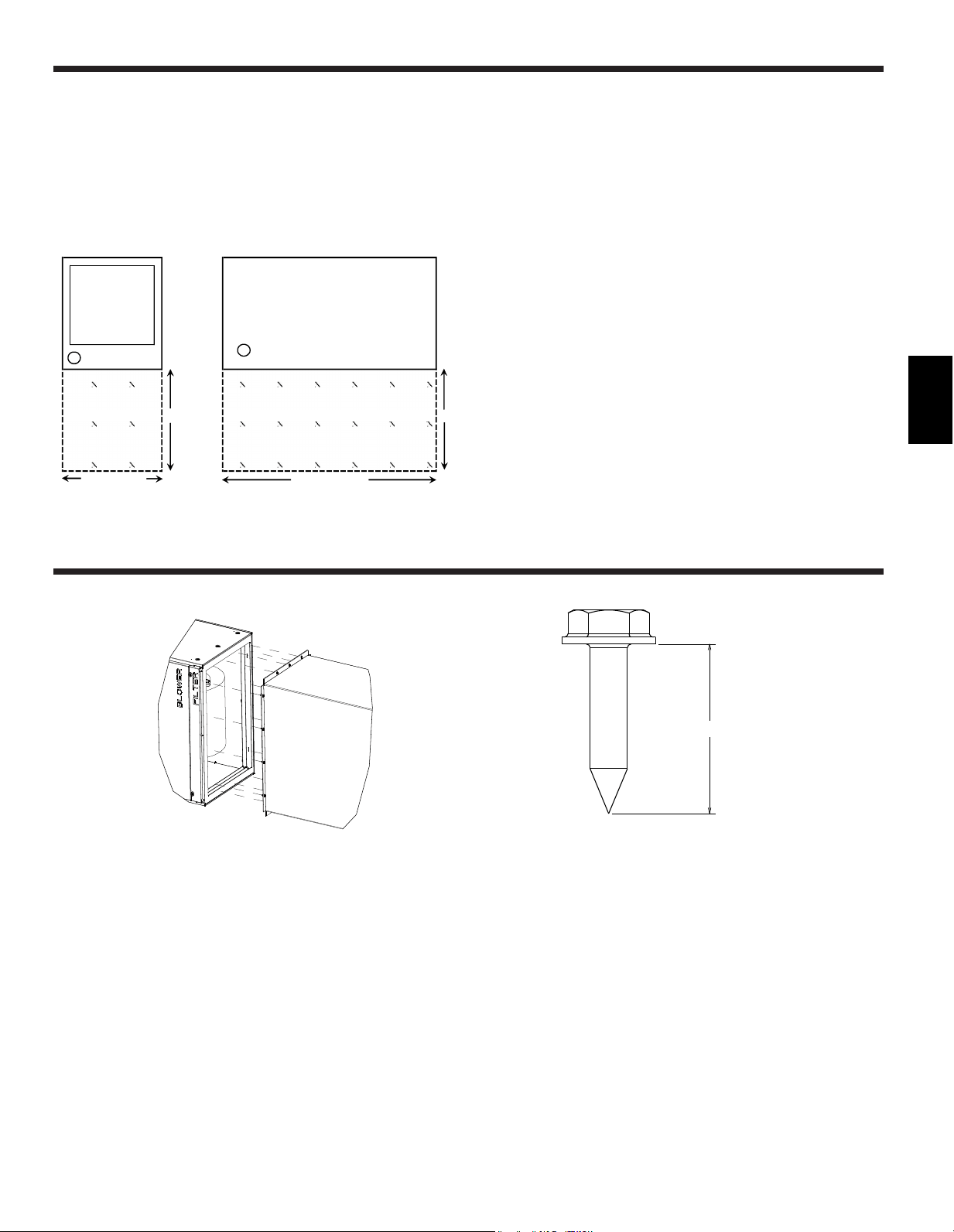
- Do not use sheetmetal screws longer that 0.75” to secure any
ductwork to the air handler
0.75" MAX
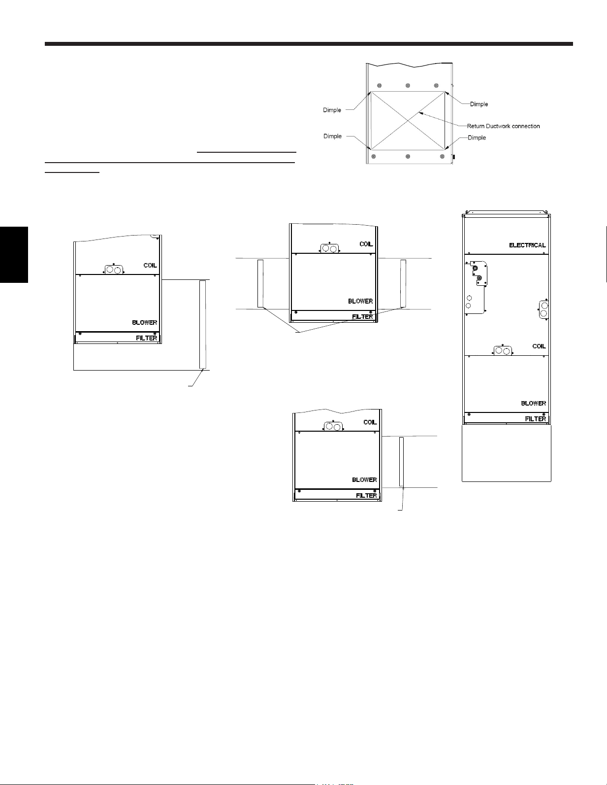
The air handler can be installed in a vertical, horizontal (Right and
Left) andDownowcon�gurationasshowninstep9.1.through9.4.
The units are designed for “0” zero clearance to combustibles. 24” is
required for service access to the front of the unit. (See Installation
Clearance)Regardlessofmountingcon�guration,theairhandler
must be mounted level to facilitate proper condensate drainage.
Installation Clearance
Insta
ll
ati
on
Cl
ea
r
an
ces
TOP View
Hor
iz
on
ta
l I
nsta
ll
ation
24"
24"
Width of Unit
TOP View
Vertica
l I
nsta
ll
ation
Le
ng
th of Unit
Clearance Area
Clearance Area
7. Installing the unit
8
EE
EN
9. Mount positions
9.1. Vertical installations
The air handler must be supported on the bottom only and set on
asolidoorwithareturnplenumbelowor�eldsuppliedsupporting
frameorplenum.Securelyattachtheairhandlertotheooror
supporting frame or plenum.
A single side return can be used for the PVA-A12 and PVA-A18
only. Dual side returns must be used on all other models to ensure
properairow.Ifthesidereturnisusedit is the responsibility of
the installer to ensure the ducts are properly sized and sealed
to the cabinet. When cutting in to the side of the cabinet, use the
provided dimples to avoid damaging any internal structure or wiring.
PLENUM
DUAL SIDE RETURN
SEAL BOTTOM OF AIR HANDLER
ADD TWO FILTERS
FILTER
PLENUM
FILTER
SIDE RETURN
SINGLE SIDE RETURN (PVA-A12, A18)
SEAL BOTTOM OF AIR HANDLER
ADD FILTER
FILTER
9
EE
EN
Auxiliary
drain pan
PRIMARY
DRAIN
3/4
”
FPT
Horizontal Right
Fan assembly rotation not required
AIRFLOW
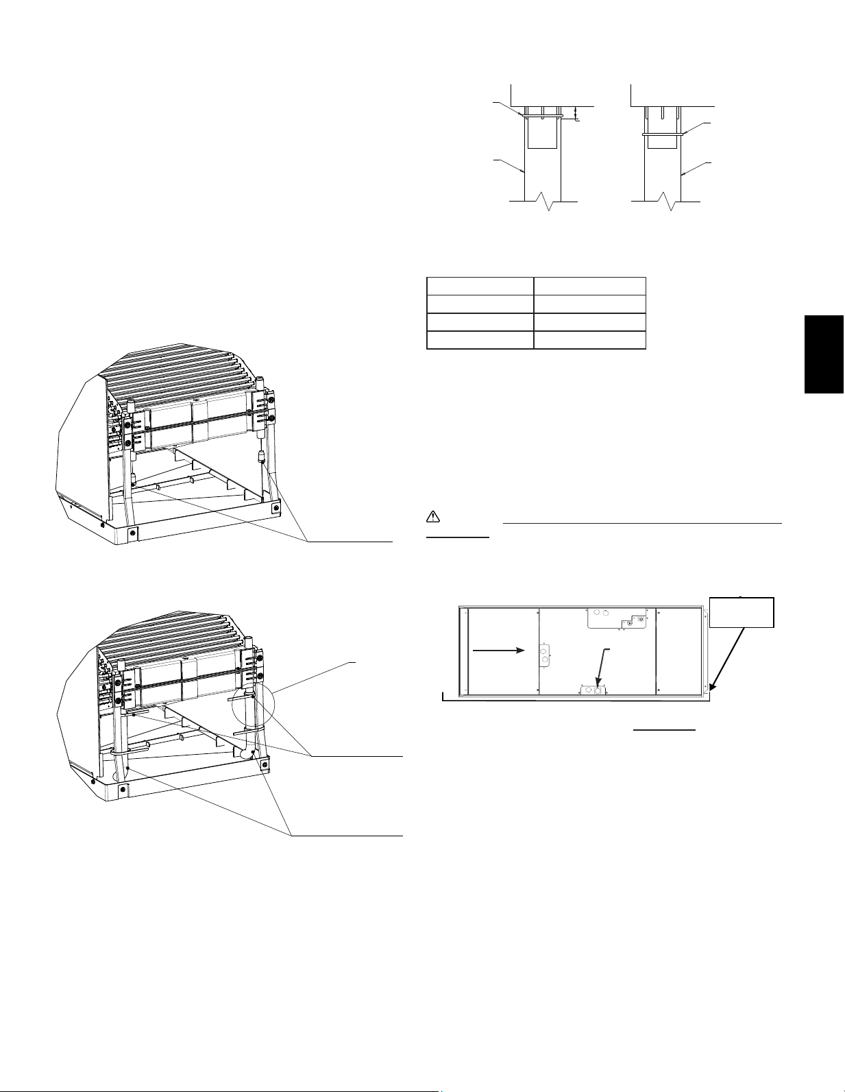
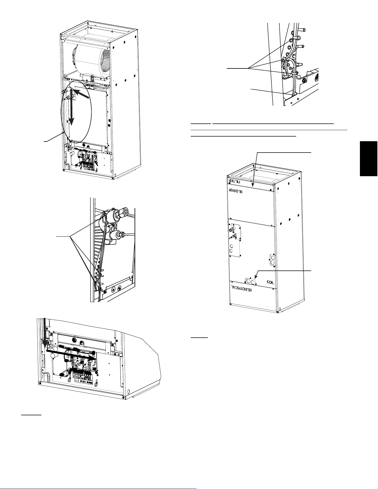
9.2. Horizontal right installations
Refer to section 9.3. Step 1 to 4 & 12 for removing the entire coil
assembly from the air handler cabinet. This will require removing
the Filter, Blower, Electrical and Coil Panels along with the brackets
that secure the coil assembly. Be sure to also route the thermistor
wires out of the electrical portion of the air handler so the coil can be
removed.
Once the coil is removed, the two clear plastic tubes included in
the accessory bag will need to be attached to the top drain pan.
First, remove the lower rubber plugs in the top drain pan. Next,
install the clear plastic tubes which are included in the accessory
bag. Ensure the plastic tubes drain into the pan. Also, be sure the
clear plastic tubes do not have any restriction. Cutting of the plastic
tube is required, please refer to the table for length. Finally, secure
the clear plastic tubes to the top drain pan per Detail A. Then to
the metal brackets supporting the coil to the top drain pan with the
provided plastic ties as shown.
Model Tube Length
PVA-A12, A18 4.9 in. (125 mm)
PVA-A24, 30 6.9 in. (175 mm)
PVA-A36, 42 *8.9 in. (225 mm)
*Tube length provided.
Reinstall the coil assembly along with bracket(s) that secure(s)
it. Failure to reinstall the brackets will result in capacity loss and
condensation formation inside the cabinet. The wiring harness for
the thermistor connector will also reroute into the electrical section
and plug into CN44. Refer to 9.3. Step 1 to 4 in reverse order to
reassemble the panels. Ensure the proper knockouts are removed
for drainage and electrical connections.
Caution:
For Horizontal installation an auxiliary drain pan must
be installed.
5/8”
(15mm)
PLASTIC TIE
PLASTIC TUBE
PLASTIC TIE
PLASTIC TUBE
CORRECT INCORRECT
DETAIL A
RUBBER PLUGS
SECURE WITH
PLASTIC TIES
2 PER SIDE
2 PLASTIC TUBES
ENSURE TUBES
DRAIN INTO PAN
SEE
DETAIL A
10
EE
EN
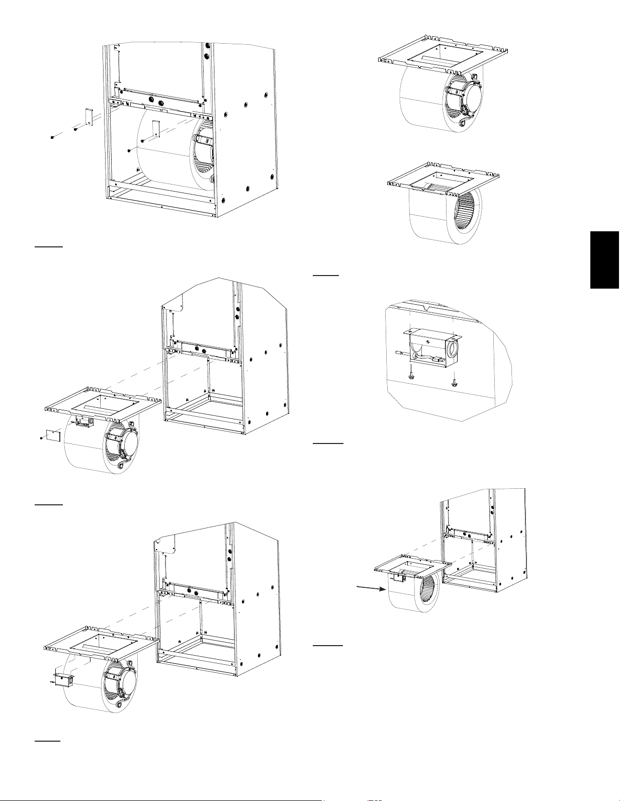
9.3. Horizontal left installations
For horizontal left installation the drain pan will need to be moved
to the opposite side of the coil. This can be done by moving the
two brackets and drain pan to the left of the coil. This way, the
condensate that formed on the coil will fall in the drain pan. Also,
the appropriate knockouts for the drains will need to be removed
once the drain pan is in its correct position.
In addition to relocating the side drain pan, the fan assembly will
also need to be removed rotated 180° and reinstalled. The motor
has to be closest to the ground. The two clear plastic tubes included
in the accessory bag will also need to be attached to the top drain
pan. See instructions below.
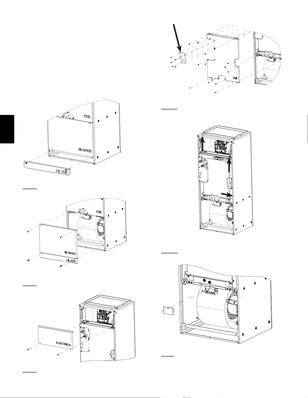
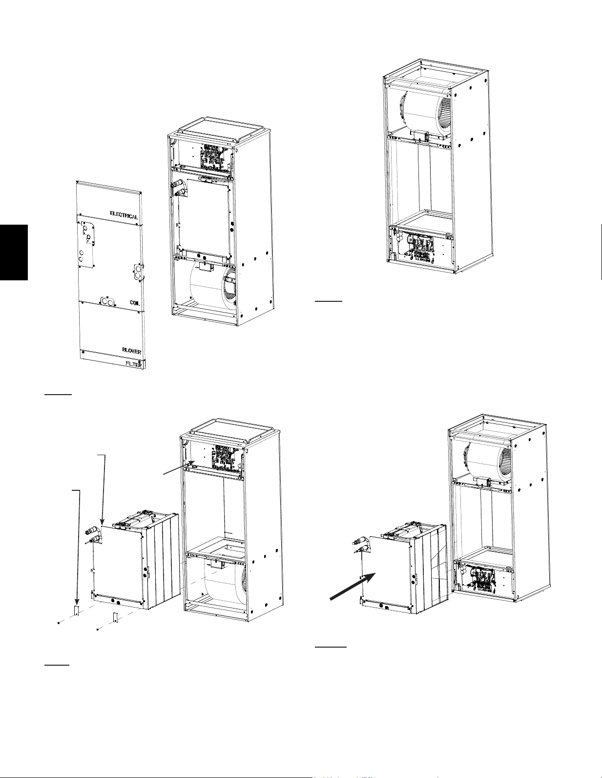
Directions for rotating fan for Horizontal Left Installation:
Step. 1 Remove the panel marked “FILTER”.
Step. 2 Remove the panel marked “BLOWER”.
Step. 3 Remove the panel marked “ELECTRICAL”
2nd
1st
Step. 4a Remove the screws securing the (3) panels to the COIL
panel shown in the image above. Remove the “1st” panel and “2nd”
panel marked “COIL”.
Step. 4b Next, remove the smaller panels covering the drain holes
andrefrigerantlinesby�rstslidinginthedirectionindicatedabove.
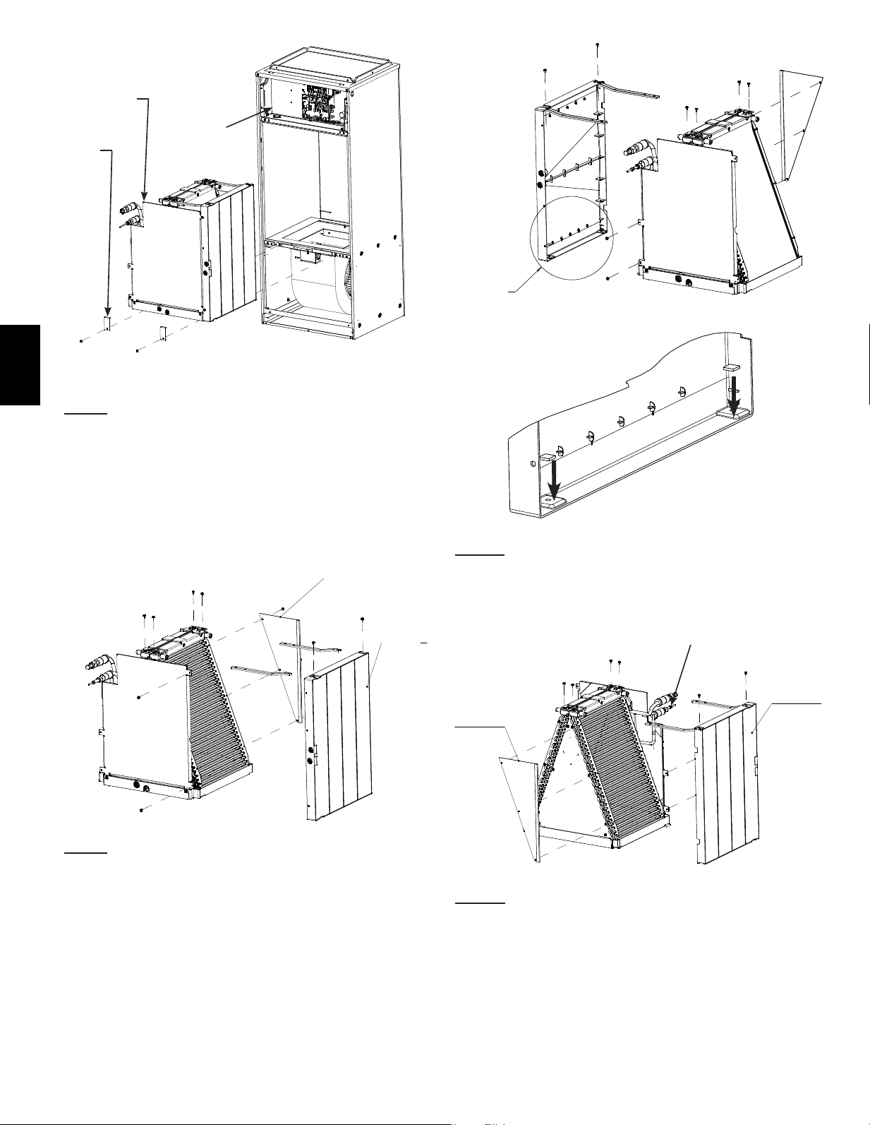
Step.5 Remove the electrical enclosure cover mounted on the fan
assembly. Disconnect the motor connector along with the connector
for the return air thermistor. Remove all of the harnesses from the
electrical enclosure leaving only the return air thermistor attached to
the electrical enclosure.
11
EE
EN
Step. 6 Remove the (4) screws indicated in the image along with the
brackets that secure the coil.
Step. 7 Slide the entire fan assembly out from the cabinet.
Step.8 Remove the electrical enclosure from the fan assembly.
Step.9 Rotate the blower assembly 180°. The motor should now be
on the opposite side.
Step.10 Reinstall the enclosure for the return air temperature
sensor on the blower assembly on the opposite side from its original
location.
Step.11 Reinsert the blower assembly with the motor now on the left
into the air handler cabinet and reuse the (2) screws that secured
the fan assembly in position. Reroute the (2) connectors for the
motor back into the enclosure and reconnect.
NOTE: The wiring harness might have to be removed from the
plastic retainers mounted to the motor bracket in order to have
sucientlengthtoreachtheelectricalenclosuremountedtothefan
assembly. Ensure wiring harness is secure so it cannot be pulled
into the fan. Reroute the return air thermistor connector back into the
electrical enclosure and reconnect.
MOTOR
ON
LEFT
12
EE
EN
A
C
B
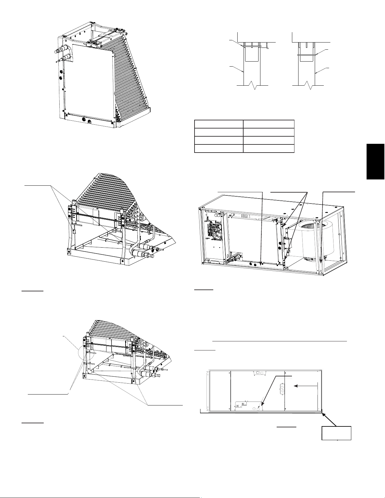
Step.12
A. Unplug the Thermistor (CN44) from the control board and route
the harness from control box area out through the rubber grommet.
B. Remove the brackets which secure the coil assembly if not
already done.
C. Slide the coil assembly out of the air handler cabinet.
Step.13 Remove the Plate Guide Rear (3 screws) and Side Drain
Pan (4 screws) along with supporting brackets (4 screws) from the
coil assembly.
PLATE GUIDE REAR
SIDE
DRAIN
PAN
DETAIL B
DETAIL B
Step.14a Install the (2) drain pan seals included in the accessory
bag as shown above. These seals will cover the unused holes in the
side drain pan to prevent leaks.
DETAIL B
Step.14b Reinstall the brackets to the opposite side of the Side
Drain Pan. The Side Drain Pan will be reinstalled on the opposite
side of the Coil Assembly. Reattach the Plate Guide Rear on the
opposite side of the coil assembly.
PIPING
PLATE
GUIDE
REAR
SIDE
DRAIN
PAN
13
EE
EN
Step.14d Next, install the clear plastic tubes which are included
in the accessory bag. Ensure the plastic tubes drain into the pan.
Also, be sure the clear plastic tubes do not have any restriction.
Cutting of the plastic tube is required, please refer to the table for
length. Finally, secure the clear plastic tubes to the top drain pan
per Detail A. Then to the metal brackets supporting the coil to the
top drain pan with the provided plastic ties as shown.
ON BOTTOM
ON BOTTOM
BRACKETS
Step.15 Reinstall the coil assembly along with bracket(s) that
secure(s) it. Failure to reinstall the brackets will result in capacity
loss and condensation formation inside the cabinet. The wiring
harness for the thermistor connector will also reroute into the
electrical section and plug into CN44. Refer to 9.3. Step 1 to 4
in reverse order to reassemble the panels. Ensure the proper
knockouts are removed for drainage and electrical connections.
NOTE: For Horizontal installation an auxiliary drain pan must be
installed.
Auxiliary
drain pan
MOTOR
ON BOTTOM
SIDE DRAIN PAN
ON BOTTOM
REATTACH
BRACKETS
PRIMARY DRAIN
3/4
”
FPT
2 PLASTIC TIES
PER SIDE
2 PLASTIC TUBES
ENSURE TUBES
DRAIN INTO
DRAIN PAN
AIRFLOW
Horizontal Left
Fan assembly rotation required
DETAIL A
Model Tube Length
PVA-A12, A18 4.9 in. (125 mm)
PVA-A24, 30 6.9 in. (175 mm)
PVA-A36, 42 *8.9 in. (225 mm)
*Tube length provided.
5/8”
(15mm)
PLASTIC TIE
PLASTIC TUBE
PLASTIC TIE
PLASTIC TUBE
CORRECT INCORRECT
DETAIL A
Completed Step. 14b View
Horizontal Left Coil Assembly
Step.14c Remove the rubber plugs indicated in the image above.
RUBBER
PLUGS
14
EE
EN
As a result of innovative multi-position design, the air handler may
beconvertedfromitsoriginalcon�gurationtoadownowposition
withouttheneedforastabilitykitorotherexternal�tting.
Operationinthedownowpositionmayresultinexcesscondensate
buildup. A Condensate Management Kit should be used to mitigate
suchwaterruno.
Step. 1 Please refer to 9.3. Steps 1 to 4 for removing the panels
which cover the Electrical, Coil Assembly, Blower and Filter.
A
B
C
Step.2
A. Unplug the Thermistor (CN44) from the control board and route
the harness from control box area out through the rubber grommet.
B. Remove the brackets which secure the coil assembly if not
already done.
C. Slide the coil assembly out of the air handler cabinet.
Step. 3 Rotate the cabinet so the Fan assembly is on top.
Step. 4a Reinsert the coil assembly back into the cabinet. The
bracket(s) are not required to be reattached.
9.4.Downowinstallations
15
EE
EN
Step. 4b Cut the plastic ties that are securing the extra wiring
for the Thermistor (CN44). Route the thermistor wires into the
Electrical section of the air handler on the left side of the coil.
-Use the metal tab in Detail A to secure the wires
-The notch in the drain pan allows the wires to pass the drain pan,
go through the sheetmetal shelf which now supports the Coil
Assembly and enter the Electrical section of the Air Handler.
Reconnect the Thermistor (CN44) to the control board.
Step. 4c In order to prevent water from running down the
Thermistor wires into the electrical area, a Drip Loop MUST be
installed to direct water into the drain pan.
3rd
1st
2nd
METAL TAB
BEND AROUND
THE WIRE
HARNESS
DRIP LOOP
TO ELECTRICAL
SECTION
DETAIL A
INSIDE DRAIN PAN
Step. 5 Reinstall the panels over the drains and refrigerant lines.
Next, install the panels which cover the Coil (1
st
), Electrical (2
nd
),
Blower (3
rd
) and Filter (4
th
). NOTE: The panel which covers the Coil
Assembly will be installed upright as the original vertical orientation
from the factory, while the other panels’ text will read upside down.
PRIMARY
DRAIN
3/4
”
FPT
4th
DÉTAIL A
16
EE
EN
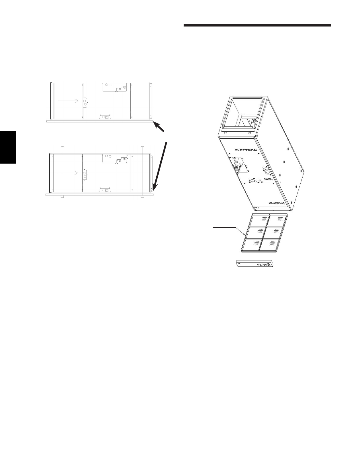
The unit can be installed on a platform or suspended from rails as
shown below. The rails must run the length of the unit and be of
sucientstrengthtosupporttheweightoftheunitandconnected
ductwork. Vibration isolation is recommended for horizontal
installations. Some jurisdictions may require an auxiliary drain pan
be mounted under the unit. Always follow local or national code
requirements.
Horizontal Mounting
Platform Mounting
10.Air�lter
Awashable(reusable)air�lterisprovidedwiththeairhandlerunit.
The�ltercanbeinstalledoncetheunithasbeenremovedfromits
packaging.Itisrecommendedtheair�lterbecleanedonceper
month.
The pressure drop is to be determined by the installing contractor
based on the overall static pressure performance of the system
including supply and return ductwork sizing. The factory static
pressureperformanceis0.50”esp.A�eldselectable0.30and0.80
esp. is available. See instructions for changing to 0.30 or 0.80 esp in
the electrical section (13.4.).
AUXILLARY
DRAIN PAN
Suspended Mounting
FILTER
17
EE
EN
11. Refrigerant piping work
Forconstraintsonpipinglengthandallowabledierenceof
elevation, refer to the design section of the engineering manual.
Themethodofpipeconnectionontheairhandlerisare
connection.
Provide proper bracing for refrigerant piping so no load is imparted
upon the connections at the air handler.
Warning:
When installing and moving the unit, do not charge it with
refrigerantotherthantherefrigerantspeci�edontheunit.
Mixingofadierentrefrigerant,air,etc.maycausethe
refrigerant cycle to malfunction and result in severe
damage.
Caution:
Use refrigerant piping made of C1220 (Cu-DHP)
phosphorousdeoxidizedcopperasspeci�edinASTM
B280 Standard for copper and copper alloy seamless
pipes and tubes. In addition, be sure that the inner
and outer surfaces of the pipes are clean and free of
hazardous sulphur, oxides, dust/dirt, shaving particles, oils,
moisture, or any other contaminant.
Never use existing refrigerant piping.
Caution: COIL UNDER PRESSURE
Always wear safety glasses when working around
pressurized devices.
The air handlers are shipped with a nitrogen holding
charge in the coil. Carefully follow these instructions when
releasing the charge.
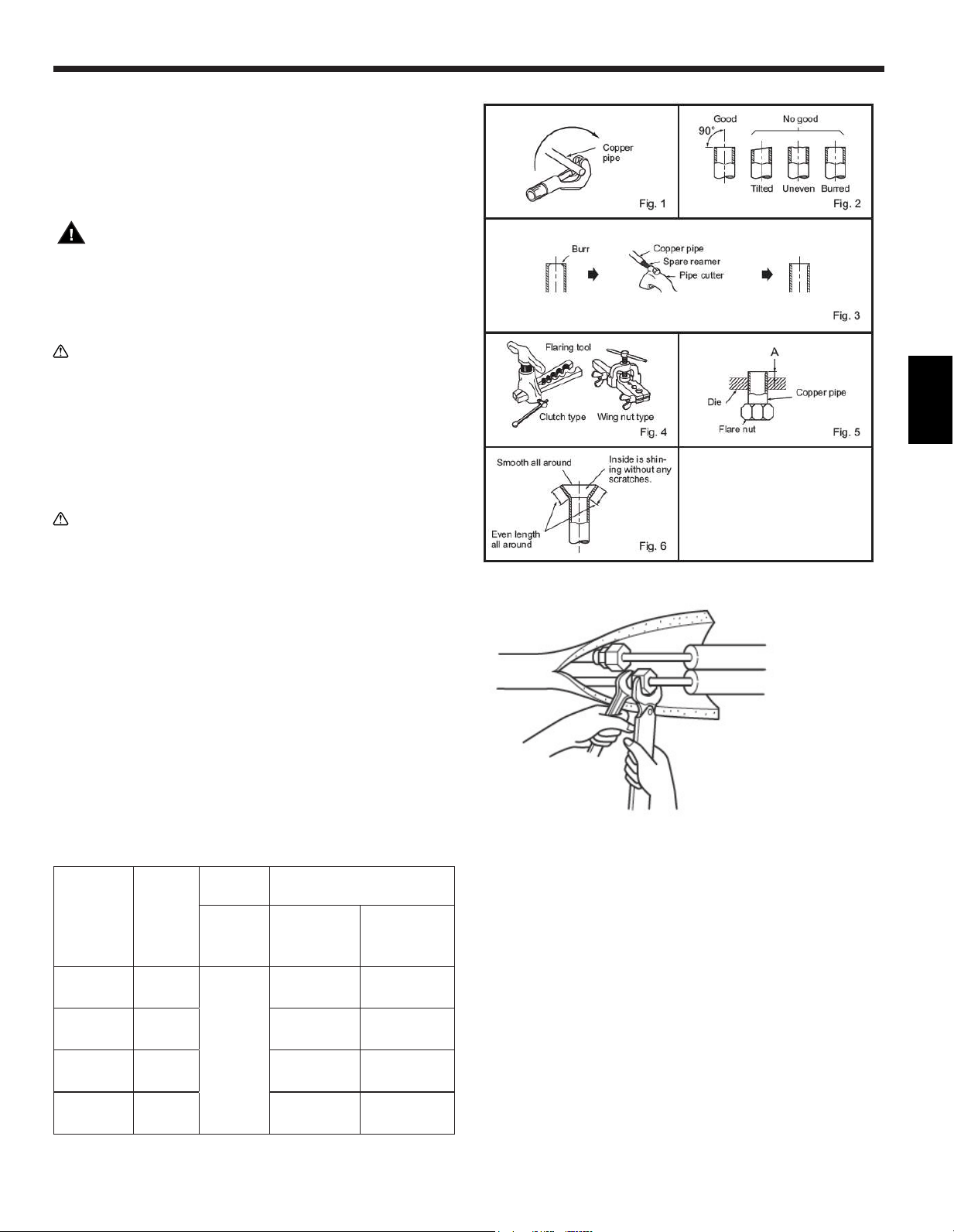
Carefullyremovethearenutotheendofthepipetoreleaseany
gas.
Both refrigerant lines need to be insulated all the way up to
the cabinet. Make sure the openings in the cabinet around the
refrigerant lines are sealed. 3/8 in thick insulation is the minimum
recommended thickness. Based on ambient conditions, local codes
and line length, thicker insulation may be desired.
Donotputanyoilonthethreadedportionofthearenuts.This
maycausethearenuttoloosenandleakrefrigerant.
Pipe
diameter
inch (mm)
Nut
(mm)
A inch
(mm)
Tightening torque
Clutch
type
tool for
R410A
N•m
lb•ft
(kgf•cm)
1/4 (6.35) (17)
0 to 0.02
(0 to 0.5)
13.7 to 17.7
10 to 13
(140 to 180)
3/8 (9.52) (22) 34.3 to 41.2
25 to 30
(350 to 420)
1/2 (12.7) (26) 49.0 to 56.4
36 to 42
(500 to 575)
5/8 (15.88) (29) 73.5 to 78.4
54 to 58
(750 to 800)
-Never use existing refrigerant piping.
-The large amount of chlorine in conventional refrigerant and
refrigerant oil in the existing piping will cause the new refrigerator to
deteriorate.
-Store the piping to be used during the installation indoors and keep
both ends of the piping sealed until just before brazing.
-If dust, dirt or water gets into the refrigerant cycle, the oil will
deteriorate and the compressor may fail.
-Use ester oil, ether oil or alkylbenzene (small amount) as the
refrigerantoiltocoataresandangeconnectionsbefore
connecting.
-The refrigerant used in the unit is highly hydroscopic and mixes
with water which will degrade the refrigerant oil.
18
EE
EN
11.1. Insulation
Toavoiddewdrops,providesucientanti-sweatinginsulationto
the refrigerant and drain pipes. When using commercially available
refrigerant pipes, be sure to cover with available insulating material
with heat-resistant temperature of more than 100 °C [212 °F] and
thickness given below, on both liquid and gas pipes. Insulate all indoor
pipes with polyethylene insulation with a minimum density of 0.03 and
athicknessasspeci�edinthetablebelow.
Pipe size Insulation thickness
6.4 mm to 25.4 mm [1/4 to 1 in.] >10 mm [7/16 in.]
28.6 mm to 38.1 mm [1-1/8 to 1-1/2 in.] >15 mm [5/8 in.]
-If the unit is used on the highest story of a building and under high
temperature and high humidity, it is necessary to use thicker insulation
thanspeci�edinthetableabove
-Iftherearecustomer’sspeci�cations,pleasefollowthem.
11.2. Piping size
Model
PVA-AA7
12-18 24-30-36-42
Refrigerant
pipe
Liquid pipe 6.35 mm [1/4] 9.52 mm [3/8]
Gas pipe 12.7 mm [1/2] 15.88 mm [5/8]
Drain Pipe O.D. 32 mm [1-1/4]
19
EE
EN
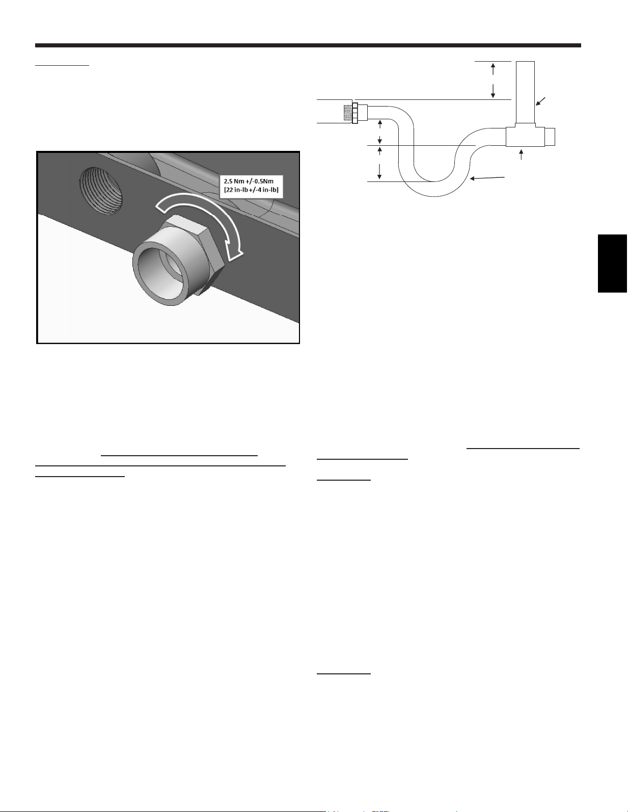
IMPORTANT!
Over-tightening the drain connections could result in drain pan
breakage and failure.
Please follow the following technique for attaching the drain pan
adapter:
1. Apply thread sealant approved for plastics.
2. Torque the drain pan adapter to 2.5 Nm +/-0.5 [22 in-lb]
The air handler contains ¾” FPT drain connections. When the unit
is used in the vertical position, there is one set. When the unit is
mounted horizontally there is one set. Each set contains a primary
drain and a secondary or auxiliary drain. The primary drain is the
one that is lowest (even with the bottom of the pan). The secondary
drain is at the higher level. They are labeled on the dimensional
drawings above.
-These units operate with a positive pressure at the drain
connections and although a P-trap is not required, it is
recommended to prevent capacity loss. Always follow local
codes and standards
-The trap needs to be installed as close to the unit as possible.
Make sure the top of the trap is below the connection to the drain
pan to allow complete drainage of the pan.
-Slope the drain line a minimum of ¼” per foot.
-Do not reduce the pipe size from ¾”, this could cause premature
blockage in the lines
-Do not braze near the plastic drain piping
2" Min.
Anti-syphon
air vent
2" Min.
2" Min.
Vent T
Drain Trap
Note:
Horizontal runs must also have an anti-siphon air vent
(standpipe) install ahead of the horizontal run to eliminate air
trapping. Horizontal drain lines must be pitched a minimum ¼” per
foot.
Route the drain lines outside or to an appropriate drain. Drain lines
must be installed so they do not block service access to the front
of the unit. 24” clearance in the front is for routine maintenance or
service.
Note:
Check local codes before connecting the drain line to an
existing drainage system.
Insulate the drain lines where sweating could cause water damage.
Upon completion of installation, it is the responsibility of the
installer to ensure the drain pan(s) captures all condensate, and all
condensate is draining properly and not getting into the ductwork/
system.
Vertical Mounting:
When mounted vertically, the air handler’s primary drain connection
is located in the center of the unit. The slightly higher drain to the
left is the secondary drain.
Attach the drain connector and tighten TO THE PROPER TORQUE
SHOWN PREVIOUSLY with sealant and install the drain line.
IMPORTANT!
Over-tightening the drain connection could result in drain pan
breakage and failure.
The secondary connection should be connected to a separate
drainage system. Run the secondary drain so the occupants will be
abletonoticewaterowingthroughthesecondarydrainindicating
a blockage in the primary drain. Optional use for the secondary is a
primarydrainlineoverowswitch(providedbyothers).Thisdevice
will shut the cooling operation unit down in the event of a primary
drain line blockage. See wiring section for connecting this device.
Horizontal (Left or Right):
If the unit is installed horizontally, remove the knockout in the front
panel to gain access to the side drain pan connections. Attach the
connector as described above and route drain line. Any vertical
drain pan openings must be covered to eliminate air loss which will
decrease the capacity of the unit.
IMPORTANT!
Over-tightening the drain connection could result in drain pan
breakage and failure.
The secondary connection should be connected to a separate
drainage system. Run the secondary drain so the occupants will be
abletonoticewaterowingthroughthesecondarydrainindicating
a blockage in the primary drain. Optional use for the secondary is a
primarydrainlineoverowswitch(providedbyothers).Thisdevice
will shut the cooling operation unit down in the event of a primary
drain line blockage. See wiring section for connecting this device.
12. Drain connections
20
EE
EN
13. Electrical wiring
Warning:
Electricalworkshouldbedonebyaquali�edelectrical
contractor in accordance with “Engineering Standards for
Electrical Installation” and supplied installation manuals.
If the power circuit lacks capacity or has an installation
failure,itmaycauseariskofelectricalshockor�re.
− Be sure to follow local and national code requirements
when wiring these units
− Install the unit in a manner to prevent that any of the
control circuit cables (remote controller, transmission
cables) are brought in direct contact with the power cable
outside the unit.
− Ensure that there is no tension on any wire connections
− Some cables (power, remote controller or transmission)
above the ceiling may become damage by accident or by
animals. Use conduit as much as possible to prevent this.
− Never connect the power cable to leads for the
transmission cables. The cables will be broken.
− Be sure to connect control cables to the indoor unit,
remote controller and the outdoor unit.
− Perform wiring in compliance with the safety regulations
detailed in UL 1995.
− Be sure to install an earth leakage breaker to the
power.
− Install the unit to prevent that any of the control circuit
cables (remote controller, transmission cables) is
brought in direct contact with the power cable outside
the unit.
− Ensure that there is no slack on all wire connections.
− Some cables (power, remote controller, transmission
cables) above the ceiling may be bitten by mouses.
Use as many metal pipes as possible to insert the
cables into them for protection.
Caution:
Be sure to ground the unit. Do not connect the grounding
cable to any gas pipe, water pipe, lightening rod, or
telephone earth cable. Incomplete grounding may cause a
risk of electrical shock.
If the supply cord is damaged, it must be replaced by
themanufacturer,itsserviceagentorsimilarlyquali�ed
persons in order to avoid a hazard.
ExternalI/Ospeci�cations
Caution:
Wiring should be covered by insulation tube with
supplementary insulation.
Use relays or switches with IEC or equivalent standard.
The electric strength between accessible parts and control
circuit should have 2750 V or more.
Wiring
Electrical wiring to the air handler will come from
the outdoor unit. Please refer to the installation
instructions for the outdoor unit.
Caution:
DO NOT POWER THE ELECTRIC HEAT FROM THE
OUTDOOR UNIT. FOLLOW THE APPROPRIATE WIR-
ING SCHEMATIC FOUND IN THE ELECTRIC HEATER
INSTRUCTIONS.
21
EE
EN
13.1. Remote controllers
Connecting remote controller, indoor and outdoor
transmission cables
Connect the “1” and “2” on the indoor unit TB15 to a remote
controller. (Non-polarized 2-wire)
Note:
Ensurethatthewiringisnotpinchedwhen�ttingtheterminalbox
cover. Pinching the wiring may cut it.
Caution:
Install wiring so that it is not tight and under tension. Wiring under
tension may break or overheat and burn.
Fixpowersourcewiringtocontrolboxbyusingbuerbushingor
tensile force. (PG connection or the like.) Connect transmission
wiring to transmission terminal block through the knockout hole of
control box using ordinary bushing.
After wiring is complete, make sure again that there is no tension
on the connections, and attach the cover onto the control box in the
reverse order removal. Also, seal any openings created from wiring
into the air handler. This will prevent air leakage.
Caution:
Wire the power supply so that no tension is imparted. Otherwise
disconnection,heatingor�remayresult.
Important:
Attach shielding ground on the outdoor unit’s ground terminal.
If the remote controller cable exceeds 10 m [32 ft.], use a 1.25 mm
2
[AWG16] diameter cable over the exceeded portion, and add that
exceeded position to within 200 m [656 ft.].
Caution:
Do not use anything other than the correct capacity breaker and
fuse. Using fuse, wire or copper wire with too large capacity
maycauseariskofmalfunctionor�re.
S1, S2, S3
GROUNDING TERMINAL
TO REMOTE CONTROLLER
1, 2
CONTROL BOARD
INVERTER BOARD
22
EE
EN
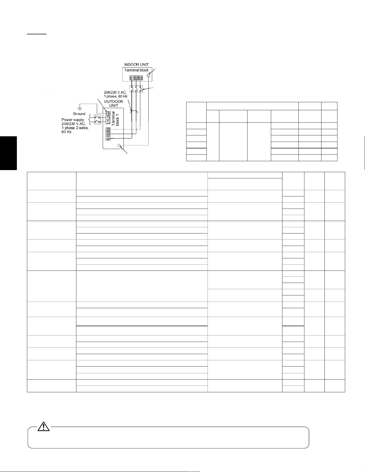
13.2. Connecting line voltage
Makesurepowersupplyiso�.
The unit should be installed by a licensed contractor/
electrician. If required by applicable national, state and local
codes; a disconnect switch will need to be installed when the
indoor unit is powered from the outdoor unit.
Function Table
Mode Settings
Mode (function) No.
Setting
no.
Initial
setting
Check
Wired remote controller
(RF thermostat)
Power failure auto
restart
Not available
01
(101)
1
1
Available 2
Indoor temperature
detecting
Indoor unit operating average
02
( - )
1
1Set by indoor unit’s remote controller 2
Remote controller’s internal sensor 3
LOSSNAY
connectivity
Not Supported
03
(103)
1
1
Supported (indoor unit is not equipped with outdoor air intake 2
Supported (indoor unit is equipped with outdoor air intake 3
Power voltage
240V (230V)
04
(104)
1
1
220V (208V) 2
Filter sign
100 Hr
07
(107)
1
32500 Hr 2
“No�ltersignindicator” 3
External static
pressure
See Section 13.4 of the installation manual
08
(108)
1
22
3
10
(110)
1
1
2
Humidi�ercontrol
Heat operation & Thermo ON
16
(116)
1
1
Heat operation 2
Humidi�er
Humidi�ernotpresent
13
(113)
1
1
Humidi�erpresent 2
Heater Control
Heater Not Present
11
(111)
1
1
Heater Present *1 2
Heater control during
defrost and error
Disable heater during Defrost and Error
23
(123)
1
1
Enable heater and fan during Defrost and Error *2 2
Fan speed thermo
oheating
Extra low
25
(125)
1
1Stop 2
RC setting 3
Fan speed thermo
ocooling
RC setting 27
(127)
1
1
Stop 2
*1 While the heater is on, the fan will operate at high speed regardless of the fan setting on the remote controller
*2 Heater will not operate during all error modes. Heater will only operate during a communication error between indoor unit and outdoor unit
Note:WhenCN4YisusedthefanisowhenCN24isenergizedwhichisonlyforusewithsupplementalheatthatisnotintheduct.
- Please see section 13.4. of the installation manual for external static pressure settings.
* If a heater is installed in the duct, do not use Panel heater connector. By doing so, the fan will turn off
when the heater is on, which may result in fire.
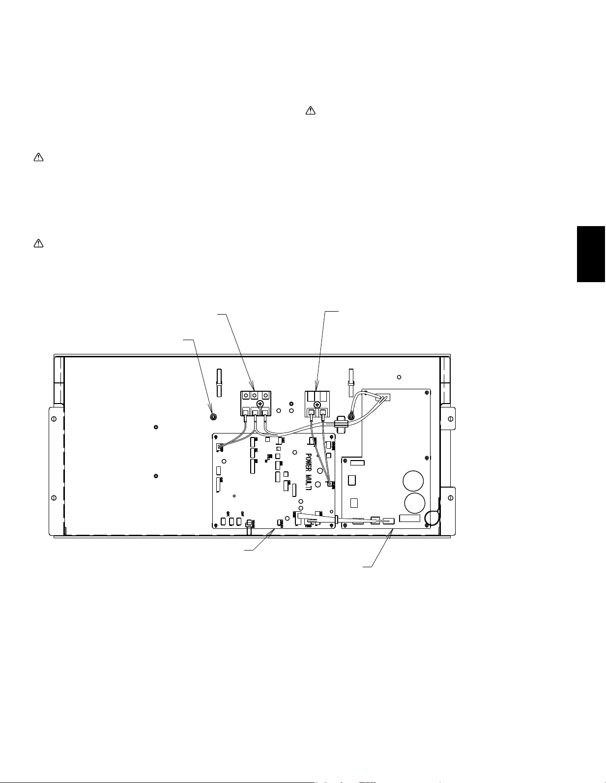
NOTE: If the air handler will be installed with electric heat
package do not power the electric heat from the outdoor unit.
All wiring must conform to National and Local codes
1. Remove the desire knockout on the air handler.
2. Attach a conduit pipe connector to the air handler and route the
wiring as shown in the above diagram. Ensure conduit connection
hole is air tight and add a sealant if necessary.
3. Firmly tighten all of the terminal screws. After tightening, verify that
the wires are tightly fastened.
Electrical Characteristics
Symbols : MCA : Max. Circuit Amps ( = 1.25 × FLA) FLA : Full Load Amps
IFM : Indoor Fan Motor Output : Fan motor rated output
Model
Indoor Unit
Hz Volts
Voltage
Range
MCA
(A)
Output
(kW)
FLA
(A)
A12
60 208/230V
188 to
253V
3.00/3.00 0.121 2.4
A18 3.00/3.00 0.121 2.4
A24 4.13/4.13 0.244 3.3
A30 4.13/4.13 0.244 3.3
A36 5.5/5.5 0.430 4.4
A42 5.63/5.63 0.430 4.5
Remark:
* Use a ring tongue terminal in
order to connect a ground wire
to terminal.
Grounding Terminal*
Grounding Terminal*
Grounding
terminal*
Disconnect
switch
23
EE
EN
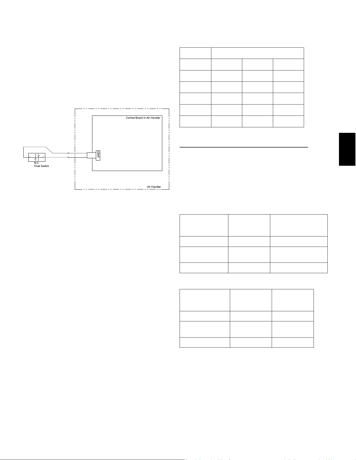
13.3.Condensateoverowsafetyswitchconnection
(CN4F)
The circuit board is equipped with a connection to attach a
condensatesafetyoatswitch.Theswitchshouldbeanormally
closed low voltage rated switch. The switch should be installed in a
location that it can sense a drain blockage causing a rise in water
level. This resulting rise in level will cause it to open. The switch
location is to be determined by the installing contractor. When the
switch opens, it will cause the LEV to close, stopping the cooling
operation. The fan will continue to run and a fault code will be shown
at the controller. Correcting the problem and closing the switch will
be required before normal operation can resume.
See installation below:
13.4. Changing blower external static pressure
The air handler is equipped with an adjustable static pressure
setting. The available settings are shown in the table below.
Model Available ESP [in. WG]
PVA-A12 0.30 0.50 0.80
PVA-A18 0.30 0.50 0.80
PVA-A24 0.30 0.50 0.80
PVA-A30 0.30 0.50 0.80
PVA-A36 0.30 0.50 0.80
PVA-A42 0.30 0.50 0.80*
*PVA-A42inDownowExternalStaticpressure:0.70
The air handler will be set to 0.50 ESP from the factory.
The air handler’s static pressure can be changed through the mode/
function settings in the controller. Please refer to the installation
manual for the controller on how to change this option. Depending
on the controller used, the mode/function will be either 08 for mode
(PAR-31 & Simple MA) or 108 for function (MHK1). Please notice
therearedierentsettingswheninstallingtheairhandlerinthe
downowposition.
Vertical, Horizontal Left, Horizontal Right External Static
Pressure Setting
External Static
Pressure
Setting No. of
Mode/Function
08/108
Setting No. of Mode/
Function 10/110
(Factory Setting)
0.3 in. WG [75Pa] 1 1
0.5 in. WG [125Pa]
(Factory Setting)
2 1
0.8 in. WG [200Pa] 3 1
DownowExternalStaticPressureSetting
External Static
Pressure
Setting No. of
Mode/Function
08/108
Setting No. of
Mode/Function
10/110
0.3 in. WG [75Pa] 1 2
0.5 in. WG [125Pa]
(Factory Setting)
2 2
0.8 in. WG [200Pa]* 3 2
*PVA-A42inDownowExternalStaticpressure:0.70
Locate the CN4F connector on the
control board. Carefully remove the
connector with the jumper from the
board. Cut the jumper on the CN4F
connector and wire a normally
closedsafetyoatswitchacross
the wires. Carefully reinstall the
connector back on the board.
When the Normally Closed Float
Switch opens, the Indoor unit will
turno.
24
EE
EN
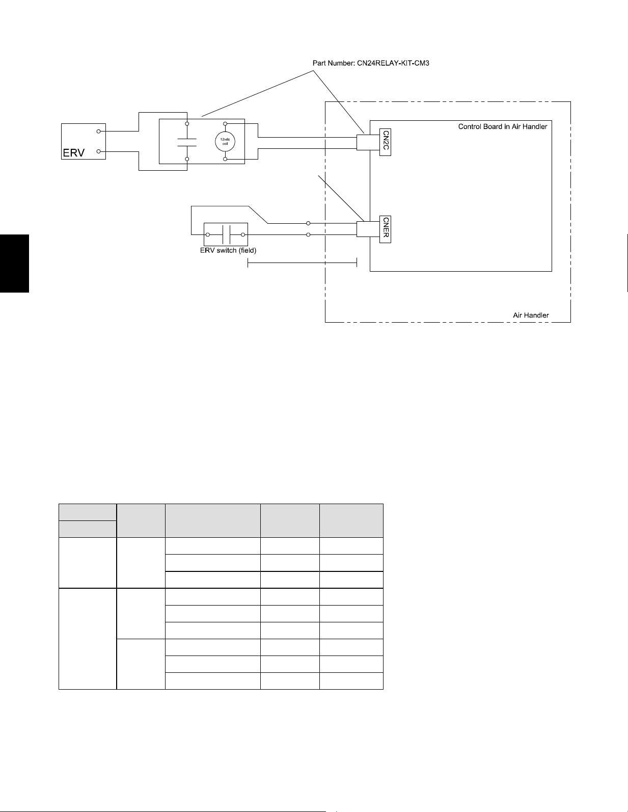
13.5. ERV (energy recovery ventilation)
Sequence of operation:
1. The ERV demand switch closes CNER
2. 12VDC is provided to CN2C to turn on ERV
3. If the unit goes into defrost, CN2C stops 12VDC output
ERV Switch:
Non-Voltage a-contact input
Contact rating voltage >= 15VDC
Contact rating current >= 0.1 A
Minimum applicable load <= 1mA at DC
ERV output
Function
Mode26
Condition Fan speed
CN2C output
(=Fan output)
CNER input
OFF -
Cool/Heat/Fan operation RC setting ON
Defrost STOP OFF
STOP STOP OFF
ON
"1"
1
Cool/Heat/Fan operation RC setting ON
Defrost STOP OFF
STOP STOP OFF
"2"
Cool/Heat/Fan operation RC setting ON
Defrost STOP OFF
STOP
RC setting
2, 3
ON
1
Factory setting.
2
When fan speed setting by RC is "Auto", Fan speed is fixed to "HIGH".
3
If ERV control is effective when STOP, IDU doesn’t report fan status or PB error (Fan motor error).
RC: Remote controller
ERV Control
max 30 ft.
Part Number: PAC-740
25
EE
EN
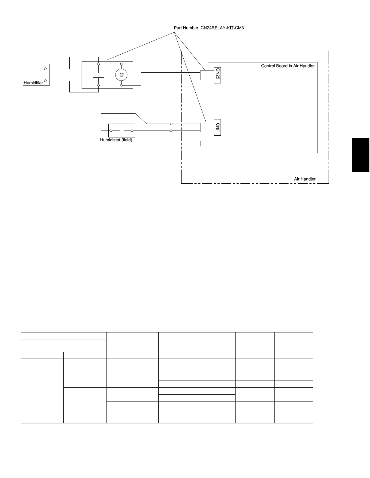
13.6.Humidi�er
Humidi�erControl
Sequence of operation:
1. The humidistat closes CNF
2. The fan starts on high
3.CN25provides12VDCtoturnontheHumidi�er
(do not exceed 1 Watt draw per relay)
4. When the Humidistat opens, the fan continues to run for
30 seconds to clear the ductwork of moist air
5.Ifdefroststartsduringhumidi�eroperation
CN25 de-energizes
Humidistat:
Non-Voltage a-contact input
Contact rating voltage >=15VDC
Contact Rating Current > = 0.1 A
Minimum Applicable Load =< 1mA at DC
Mode (function) No.
Humidistat Output
Condition
(No Defrost/No Error)
CN25 Output Fan Speed
Wired remote controller ( RF
thermostat)
13 (113) 16 (116) CNF Input
2
1*
OFF
Heat operation & Thermo OFF
OFF RC setting
Heat operation & Thermo ON
ON
Heat operation & Thermo OFF OFF RC setting
Heat operation & Thermo ON ON High
2
OFF
Heat operation & Thermo OFF
OFF RC setting
Heat operation & Thermo ON
ON
Heat operation & Thermo OFF
ON High
Heat operation & Thermo ON
1 - - Nohumidi�eroperation OFF RC setting
RC: Remote controller
Thefancontinuestorunfor30secondsafterthehumidi�erstops.
*Factory Setting
max 30 ft.
26
EE
EN
14. Test run
14.1. Before test run
After completing installation and the wiring and piping of
the indoor and outdoor units, check for refrigerant leakage,
looseness in the power supply or control wiring, wrong polarity,
and no disconnection of one phase in the supply.
Use a 500-volt megohmmeter to check that the resistance
between the power supply terminals and ground is at least 1.0
MΩ.
Do not carry out this test on the control wiring (low voltage
circuit) terminals.
Warning:
Do not use the air conditioner if the insulation
resistanceislessthan1.0MΩ.
After installation or after the power source to the unit has been cut
for an extended period, the insulation resistance will drop below 1
MΩduetorefrigerantaccumulatinginthecompressor.Thisisnota
malfunction. Perform the following procedures.
1. Remove the wires from the compressor and measure the
insulation resistance of the compressor.
2.Iftheinsulationresistanceisbelow1MΩ,thecompressorisfaulty
or the resistance dropped due the accumulation of refrigerant in the
compressor.
3. After connecting the wires to the compressor, the compressor will
start to warm up after power is supplied. After supplying power for
the times indicated below, measure the insulation resistance again.
• The insulation resistance drops due to accumulation of refrigerant
inthecompressor.Theresistancewillriseabove1MΩafterthe
compressor is warmed up for two to three hours.
(The time necessary to warm up the compressor varies according to
atmospheric conditions and refrigerant accumulation.)
• To operate the compressor with refrigerant accumulated in the
compressor, the compressor must be warmed up at least 12 hours to
prevent breakdown.
4.Iftheinsulationresistancerisesabove1MΩ,thecompressoris
not faulty.
Caution:
• The compressor will not operate unless the power
supply phase connection is correct.
• Turn on the power at least 12 hours before starting
operation.
− Starting operation immediately after turning on the main
power switch can result in severe damage to internal parts.
Keep the power switch turned on during the operational
season.
14.3. Self-check
Refer to the installation manual that comes with each remote controller for details.
RF thermostat is not established.
[Output pattern A] Errors detected by indoor unit
IR wireless remote controller
Wired remote controller
RF thermostat
Symptom Remark
Beeper sounds/OPERATION
INDICATORlampashes
(Number of times)
Check code
1 P1 Intake sensor error
2 P2, P9 Pipe (Liquid or 2-phase pipe) sensor error
3 E6, E7 Indoor/outdoor unit communication error
4 P4 Drain sensor error
5 P5 Drain pump error
6 P6 Freezing/Overheating safeguard operation
7 EE Communication error between indoor and outdoor units
8 P8 Pipe temperature error
9 E4 Remote controller signal receiving error
10 – –
11 Pb Fan motor error
12 Fb Indoor unit control system error (memory error, etc.)
No sound – – No corresponding
14.2. Test run
Refer to the installation manual that comes with each remote controller for details.
27
EE
EN
[Output pattern B] Errors detected by unit other than indoor unit (outdoor unit, etc.)
IR wireless remote controller
Wired remote controller
RF thermostat
Symptom Remark
Beeper sounds/OPERATION
INDICATORlampashes
(Number of times)
Check code
1 E9 Indoor/outdoor unit communication error (Transmitting error)
(Outdoor unit)
2 UP Compressor overcurrent interruption
3 U3, U4 Open/short of outdoor unit thermistors
4 UF Compressor overcurrent interruption (When compressor locked)
5 U2 Abnormalhighdischargingtemperature/49Cworked/insucientrefriger-
ant
6 U1, Ud Abnormal high pressure (63H worked)/ Overheating safeguard operation
7 U5 Abnormal temperature of heat sink
8 U8 Outdoor unit fan protection stop
9 U6 Compressor overcurrent interruption/Abnormal of power module
10 U7 Abnormality of super heat due to low discharge temperature
11 U9, UH Abnormality such as overvoltage or voltage shortage and abnormal and
synchronous signal to main circuit/Current sensor error
12 – –
13 – –
14 Others Other errors (Refer to the technical manual for the outdoor unit.)
*1Ifthebeeperdoesnotsoundagainaftertheinitialtwobeepstocon�rmtheself-checkstartsignalwasreceivedandthe
OPERATION INDICATOR lamp does not come on, there are no error records.
*2Ifthebeepersoundsthreetimescontinuously“beep,beep,beep(0.4+0.4+0.4sec.)”aftertheinitialtwobeepstocon�rmthe
self-checkstartsignalwasreceived,thespeci�edrefrigerantaddressisincorrect.
• On IR wireless remote controller
The continuous buzzer sounds from receiving section of indoor unit.
Blink of operation lamp
• On wired remote controller
Check code displayed on the LCD.
• If the unit cannot be operated properly after the above test run has been performed, refer to the following table to remove the cause.
Symptom
Cause
Wired remote controller LED 1, 2 (PCB in outdoor unit)
PLEASE WAIT
For about 2 minutes
following power-on
After LED 1, 2 are lighted, LED 2 is turned
o,thenonlyLED1islighted.(Correct
operation)
• For about 2 minutes after power-on, operation of the
remote controller is not possible due to system start-up.
(Correct operation)
PLEASEWAIT→Errorcode
After about 2 minutes
has expired
following power-on
OnlyLED1islighted.→LED1,2blink.
• Connector for the outdoor unit’s protection device is not
connected.
• Reverse or open phase wiring for the outdoor unit’s power
terminal block (L1, L2, L3)
Display messages do not appear
even when operation switch is
turned ON (operation lamp does
not light up).
OnlyLED1islighted.→LED1,2blinks
twice, LED 2 blinks once.
• Incorrect wiring between indoor and outdoor units
(incorrect polarity of S1, S2, S3)
• Remote controller wire short
On the IR wireless remote controller with conditions above, following phenomena takes place.
• No signals from the remote controller are accepted.
• OPE lamp is blinking.
• The buzzer makes a short ping sound.
Note:
Operation is not possible for about 30 seconds after cancellation of function selection. (Correct operation)
For description of each LED (LED1, 2, 3) provided on the indoor controller, refer to the following table.
LED 1 (power for microcomputer) Indicates whether control power is supplied. Make sure that this LED is always lit.
LED 2 (power for remote controller)
Indicates whether power is supplied to the remote controller. This LED lights only in the case of
the indoor unit which is connected to the outdoor unit refrigerant address “0”.
LED 3 (communication between indoor and outdoor units)
Indicates state of communication between the indoor and outdoor units. Make sure that this LED is
always blinking.

28
EE
EN
14.4. AUTO RESTART FUNCTION
Indoor controller board
This model is equipped with the AUTO RESTART FUNCTION.
When the indoor unit is controlled with the remote controller, the operation mode,
set temperature, and the fan speed are memorized by the indoor controller board.
The auto restart function sets to work the moment the power has restored after
power failure, then, the unit will restart automatically.
Set the AUTO RESTART FUNCTION using the remote controller. (Mode no.01)

29
FR
Table des matières
Table des matières ...................................................................29
1. Dimensions ...........................................................................30
2.Véri�cationdelalivraison .....................................................31
3.Consignesdesécurité ..........................................................31
3.1.Avantl’installation de l’appareil et l’installation
électrique ......................................................................31
3.2.Précautionsàprendreaveclesappareilsutilisantle
réfrigérant R410A .........................................................32
3.3.Avantdecommencer ...................................................32
3.4.Avantdeprocéderàl’installation(audéplacement)-
installationélectrique ...................................................33
3.5.Avantd’effectuerl’essaidefonctionnement .................33
4.Accessoiresdel’appareilintérieur ........................................33
5.Sélectiondel’emplacementd’installation ............................33
6.Combinaisondesappareilsintérieursavecdesappareils
extérieurs ..............................................................................33
7. Installation de l’appareil ........................................................34
8.Raccordementdesconduits .................................................34
9. Positions de montage ...........................................................35
9.1.Installationverticale .....................................................35
9.2.Installationhorizontaleducôtédroit ............................36
9.3.Installationhorizontaleducôtégauche .......................37
9.4.Installationenuxdescendant ....................................41
10.Filtreàair............................................................................43
11.Miseenplacedestuyauxderéfrigérant .............................44
11.1. Isolation ......................................................................45
11.2.Tailledestuyaux .........................................................45
12.Raccordsd’évacuation .......................................................46
13.Câblageélectrique..............................................................47
13.1.Commandesàdistance .............................................48
13.2.Raccordementàlatensiondeligne,Tableaudesfon-
ctions ...............................................................................49
13.3.Connexiondel’interrupteurdesécuritéde
débordementdecondensat(CN4F) ..........................51
13.4.Modi�cationdelapressionstatiqueextérieure(PSE)
duventilateur .............................................................51
13.5.Ventilationavecrécupérationd’énergie(ERV) ..........52
13.6.Humidi�cateur ............................................................53
14.Essaidefonctionnement ....................................................54
14.1.Avantl’essaidefonctionnement ................................54
14.2.Essaidefonctionnement ...........................................54
14.3.Autocontrôle ...............................................................54
14.4.FONCTIONDEREDÉMARRAGEAUTOMATIQUE ..56
30
FR
1. Dimensions
Modèle
Taille du filtre nominal
Raccordement des conduits
PVA-A30AA4
508X508X25,4
477X402
J
77,8(3-1/8)
66(2-5/8)
36,8(1-1/2)
43(1-3/4) 8(3/8)
92(3-5/8) 30(1-3/16)
43(1-3/4)
8(3/8)
55(2-3/16)
548(21-5/8)
117,4 (4-5/8)
402(15-7/8)
B (Conduit)
28,8(1-3/16)
76(3)
C
A
D
525,5(20-3/4)50,8(2)470(18-9/16)
H
55(2-3/16)
G
70(2-13/16)
8(3/8)
F
55(2-3/16)
E
24(15/16)
13,2(9/16)
Boîte de commande
Filtre à air
Sortie d’air
Entrée d’air
(Conduit)
Connexion par évasement des
tuyaux de réfrigérant (gaz)
Connexion par évasement des
tuyaux de réfrigérant (liquide)
Tuyau d’évacuation principale
(évacuation par gravité)
ø19,05(3/4) 3/4" FPT
Tuyau d’évacuation secondaire
(évacuation d’urgence)
ø19,05(3/4) 3/4" FPT
Tuyau d’évacuation principale
(évacuation par gravité)
ø19,05(3/4) 3/4" FPT
(Installation horizontale du côté gauche)
(Installation horizontale du côté droit)
Tuyau d’évacuation secondaire
(évacuation d’urgence)
ø19,05(3/4) 3/4" FPT
Tuyau d’évacuation principale
(évacuation par gravité)
ø19,05(3/4) 3/4" FPT
Tuyau d’évacuation secondaire
(évacuation d’urgence)
ø19,05(3/4) 3/4" FPT
Bornier
(Connexion de l’appareil intérieur/extérieur)
Bornier
(Transmission de la commande à distance)
2-ø4,6 Trous d’ébavurage pour
l’installation du chauffage électrique
ø26 Orifice défonçable
(Transmission de la commande à distance)
ø26 Orifice défonçable
ø26
Orifice défonçable
ø26 Orifice défonçable
(Connexion de l’appareil intérieur/extérieur)
(Connexion de l’appareil
intérieur/extérieur)
(Transmission de la commande à distance)
Remarque 1 : Conservez un espace de service pour l’entretien à l’avant.
Haut
Vue de
dessus
Vue de
face
Bas
Vue de
dessous
Vue de
gauche
Vue de
droite
3
3
2
1
Modél A B C D E F G H J
�Tuyau de gaz Tuyau de liquide
PVA-A12AA7
432 (17) 376 (14-13/16) 281 (11-1/8) 224 (8-7/8) 1275 (50-1/4) 680 (26-13/16) 823 (32-7/16) 735,5 (29) 360 (14-3/16) Φ12,7(1/2) Φ6,35(1/4)
PVA-A18AA7
PVA-A24AA7
534 (21) 477 (18-13/16) 382,6 (15-1/8) 266,5 (10-1/2) 1378 (54-1/4) 737 (29-1/16) 953,5 (37-9/16) 792 (31-3/16) 461 (18-3/16)
Φ15,88(5/8) Φ9,52(3/8)
PVA-A30AA7
PVA-A36AA7
635 (25) 579 (22-13/16) 484,6 (19-1/8) 317,5 (12-1/2) 1511 (59-1/2) 798,5 (31-7/16) 1053 (41-1/2) 853,5 (33-5/8) 563 (22-3/16)
PVA-A42AA7
Modél
Tailledu�ltre
nominal
Raccordement des
conduits
PVA-A12AA7 508 x 406,4 x 25,4
(20 x 16 x 1)
376 x 402
(14-13/16 x 15-7/8)
PVA-A18AA7
PVA-A24AA7 508 x 508 x 25,4
(20 x 20 x 1)
477 x 402
(18-13/16 x 15-7/8)
PVA-A30AA7
PVA-A36AA7 508 x 609,6 x 25,4
(20 x 24 x 1)
579 x 402
(22-13/16 x 15-7/8)
PVA-A42AA7
Unit: mm (in.)
31
FR
3.1. Avant l’installation de l’appareil et l’installation
électrique
Avantd’installerl’appareil,lisezattentivementtoutesles
“Consignesdesécurité”.
Les“Consignesdesécurité”concernentdespointstrès
importantsenmatièredesécurité.Veillezàbienlessuivre.
Symboles utilisés dans le texte
Avertissement :
Décritlesprécautionsàsuivrepourévitertoutdangerde
blessureoudedécèsdel’utilisateur
Précaution:
Décritlesprécautionsàsuivrepouréviterd’endommager
l’appareil
Avertissement :
Lisez soigneusement les étiquettes se trouvant sur
l’appareil principal.
Avertissement :
• L’appareil doit être installé par un revendeur agréé ou
untechnicienquali�é.
− Unemauvaiseinstallationparl’utilisateurpourrait
provoquerdesfuitesd’eau,uneélectrocutionouun
incendie.
• Installez l’appareil sur une structure capable de
supporter son poids.
− Autrementl’appareilrisquedetomberetdeblesser
quelqu’un.
• Utilisezlescâblesspéci�éspourlecâblage.
Assurez-vous que les raccordements sont effectués
correctement de façon à ce que la force externe du
câble ne soit pas appliquée aux bornes.
− Unraccordementetune�xationinadéquatspourraient
provoquerunesurchauffeetcauserunincendie.Utilisez
desserre-câbleslorsducâblage.
• Prenez toutes les mesures nécessaires pour parer aux
éventuels typhons, ouragans, tremblements de terre,
etc.etinstallezl’appareilàl’endroitspéci�é.
− L’appareilpourraittomberetparconséquentblesser
quelqu’unsil’installationn’estpaseffectuéecorrectement.
• Ne réparez jamais vous-même l’appareil. En cas de
réparation nécessaire du climatiseur, veuillez consulter
le revendeur.
− Toutemauvaiseréparationpeutentraînerunrisquede
fuited’eau,d’électrocutionoud’incendie.
• Ne touchez pas les ailettes de l’échangeur thermique.
− Unemanipulationinappropriéepeutentraînerdes
blessures.
• Lors de la manipulation du produit, portez toujours des
vêtements de protection.
− Parexemple:gants,protectionintégraledesbraset
lunettesdesécurité.
− Unemanipulationinappropriéepeutentraînerdes
blessures.
• Installez le climatiseur en respectant les instructions de
ce manuel d’installation.
− Sil’appareiln’estpascorrectementinstallé,ilpeutyavoir
unrisquedefuited’eau,d’électrocutionoud’incendie.
• Demandezàunélectricienquali�éd’effectuer
l’installation électrique conformément aux
“Normes électriques nationales et locales” et aux
“Réglementations sur le câblage intérieur” ainsi qu’aux
instructions de ce manuel, et utilisez toujours un circuit
spéci�que.
− Silacapacitédelasourced’alimentationn’estpas
adéquateousil’installationélectriquen’estpaseffectuée
correctement,ilpeutyavoirunrisqued’électrocutionou
d’incendie.
• Maintenez les pièces électriques à l’abri de l’eau (eau
de lavage etc.).
− Celapourraitprovoqueruneélectrocution,unincendieou
delafumée
.
• Lors du nettoyage de l’échangeur thermique et du
bac de récupération, assurez-vous que la boîte de
commande, le moteur et le LEV restent secs en utilisant
une couverture étanche.
• Lors de l’installation et du déplacement du climatiseur
vers un autre site, ne le chargez pas avec un réfrigérant
différentdeceluiquiestspéci�ésurl’appareil.
− Siunautreréfrigérantoudel’airestmélangéau
réfrigérantd’origine,lecyclederéfrigérationpeutmal
fonctionneretl’appareilpeutêtreendommagé.
• Lors du déplacement et de la réinstallation du
climatiseur, veuillez consulter le revendeur ou un
technicien agréé.
− Unemauvaiseinstallationduclimatiseurpeutentraînerun
risquedefuited’eau,d’électrocutionoud’incendie.
• Neréarrangezpasounemodi�ezpaslesréglagesdes
dispositifs de sécurité.
− Silepressostat,l’interrupteurthermiqueoutoutautre
dispositifdesécuritéestcourt-circuitéetforcé,ousides
piècesautresquecellesspéci�éesparMitsubishiElectric
sontutilisées,unincendieouuneexplosionpeuten
résulter.
• Demandez conseil à votre revendeur pour la mise au
rebut de ce produit.
• N’utilisez pas d’additif de détection de fuite.
• Utiliseztoujoursles�ltresàair,humidi�cateurs,
chauffagesélectriquesetautresaccessoiresspéci�és
par Mitsubishi Electric.
− Demandezàuntechnicienagrééd’installerles
accessoires.Unemauvaiseinstallationparl’utilisateur
pourraitprovoquerdesfuitesd’eau,uneélectrocutionou
unincendie.
• En cas de fuite de gaz réfrigérant durant l’installation,
aérez la pièce.
− Silegazréfrigérantentreencontactavecuneamme,ily
auraémissiondegaztoxiques.
• Mettez fermement en place le couvercle des bornes de
l’appareil extérieur (panneau).
− Silecouvercledesbornes(panneau)n’estpasmisen
placecorrectement,delapoussièreoudel’eaupeut
pénétrerdansl’appareilextérieuretentraînerunincendie
ouuneélectrocution.
3. Consignes de sécurité
2.Véri�cationdelalivraison
Cescentralesdetraitementd’airsontentièrement
assembléesenusineetlaperformancedetousles
composantsesttestée.Chaqueappareilestconstitué
d’unblocventilateur,d’unebobinederéfrigérantetde
commandesintégrésdansuncaissonenaciergalvanisé
isoléenusine.Lesori�cesdéfonçablessontfournis
pourlepassagedescâblesélectriques.Véri�ezla
plaquesignalétiquedel’appareilpourcon�rmerque
lesspéci�cationscorrespondent.Dèslaréceptionde
l’équipement,inspectez-lesoigneusementpourvéri�er
qu’ilneprésenteaucundommage.Faitesparticulièrement
attentionlorsquevousinspectezl’appareilsilecarton
d’emballageestendommagé.Encasdedommage,
veuillezlenotersurlafacturedutransporteur.Toutes
réclamationsdedommagesdoiventêtredéposéesauprès
dutransporteurimmédiatement.Toutesréclamationsde
piècesmanquantesdoiventêtredéposéesauprèsdu
revendeurdansles5joursdelaréception.
32
FR
• Si le climatiseur est installé dans une pièce
relativement petite, certaines mesures doivent être
prises pour éviter que la concentration de réfrigérant
ne dépasse le seuil de sécurité en tenant compte des
possibilités de fuites de réfrigérant.
− Consultezvotrerevendeursurlesprécautionsnécessaires
àprendrea�nquelalimiteadmissiblenesoitpas
dépassée.Sileréfrigérantfuitetquelalimiteadmissible
estdépassée,desrisquesdusaumanqued’oxygènedans
lapiècepeuventexister.
• Une fois l’installation terminée, assurez-vous qu’il n’y a
aucune fuite de gaz réfrigérant.
− Silegazréfrigérantfuitetestexposéàunradiateur
soufant,unpoêle,unfouroutouteautresourcede
chaleur,desgaztoxiquespeuventêtreémis.
• Les enfants ne doivent pas être autorisés autour de
l’équipement de climatisation.
• L’installateur et le spécialiste du système doivent
s’assurer qu’il n’y a pas de fuite de réfrigérant
conformément aux normes et règlements locaux.
• Faites particulièrement attention à l’emplacement
d’installation de l’appareil. Étant donné que le
réfrigérant est plus lourd que l’air, des emplacements
tels qu’un sous-sol ou un vide sanitaire où le gaz
réfrigérant peut s’accumuler peuvent devenir
dangereux.
• Cet appareil n’est pas destiné à être utilisé par des
personnes (enfants inclus) dont les capacités mentales,
sensorielles ou physiques sont réduites, ou qui ne
disposent pas de l’expérience et des connaissances
requises, sauf si une personne responsable de leur
sécurité assure leur surveillance ou leur formation dans
le cadre de l’utilisation de l’appareil.
• Si le cordon d’alimentation est endommagé, il doit être
remplacé par le fabricant, un agent d’entretien ou une
personnequali�éedemanièreàévitertoutrisque.
• Utilisez uniquement un réfrigérant de type indiqué dans
les manuels fournis avec l’appareil et sur la plaque
signalétique.
− Fautedequoi,l’appareiloulatuyauteriepourraitéclater,
oucelapourraitprovoqueruneexplosionouunincendie
pendantl’utilisation,laréparationoulamiseaurebutde
l’appareil.
− Celapourraitégalementconstitueruneviolationdeslois
applicables.
− MITSUBISHIELECTRICCORPORATIONnepeutêtre
tenueresponsabledetoutdysfonctionnementouaccident
résultantdel’utilisationdumauvaistypederéfrigérant.
3.2. Précautions à prendre avec les appareils utilisant
le réfrigérant R410A
Précaution :
• N’utilisez pas les tuyaux de réfrigérant actuels.
−
Levieuxréfrigérantetl’huilederéfrigérationsetrouvant
danslestuyauxcontiennentunelargequantitédechlore
quipourraitabîmerl’huilederéfrigérationdunouvel
appareil.
• Utilisez des tuyaux de réfrigération en cuivre désoxydé
au phosphore C1220 (Cu-DHP) comme indiqué par
la norme JIS H3300 “Tuyaux et tubes en cuivre ou en
alliage de cuivre sans soudure”. Veillez également à
ce que les surfaces internes et externes des tuyaux
soient propres et dépourvues de soufre, d’oxydes,
de poussière/impuretés, de rognures, d’huile, de
condensation ou de toute autre particule contaminante.
− Toutcontaminantàl’intérieurdestuyauxderéfrigération
pourraitprovoquerladétériorationdel’huilede
réfrigérationrésiduelle.
• Gardez les tuyaux à utiliser pour l’installation à
l’intérieur et laissez les deux extrémités des tuyaux
couvertes jusqu’au moment du brasage. (Gardez les
tuyaux coudés et autres raccords dans un sac en
plastique.)
− Sidelapoussière,delasaletéoudel’eaus’in�ltre
danslecyclederéfrigération,leréfrigérantrisquedese
détérioreretlecompresseurrisquedenepasfonctionner
correctement.
• Utilisez un réfrigérant liquide pour remplir le système.
− Sil’onutilisedugazréfrigérantpourrendrelesystème
hermétique,lacompositionduréfrigérantsetrouvantdans
lecylindrechangeraetlaperformancepeutchuter.
• N’utilisez pas un réfrigérant autre que le R410A.
− Siunautreréfrigérantestutilisé,lechloreprésentdans
leréfrigérantpeutprovoquerladétériorationdel’huilede
réfrigération.
• Utilisez une pompe à vide équipée d’une valve de
contrôledeuxinverse.
− Ilsepeutquel’huiledelapompeàviderepartedansle
cyclederéfrigération,cequientraîneraitladétérioration
del’huilederéfrigération.
• N’utilisez pas les outils énumérés ci-dessous, destinés
aux réfrigérants traditionnels.
− (Manomètredepression,tuyauexibledecharge,
détecteurdefuitedegaz,valvedecontrôledeux
inverse,basedechargeduréfrigérant,jaugeàvide,
équipementsderécupérationderéfrigérant.)
− Sileréfrigérantconventionneletl’huilederéfrigération
sontmélangésauR410A,leréfrigérantpeutsedétériorer.
− Sidel’eauestmélangéeauR410A,l’huilederéfrigération
peutsedétériorer.
− PuisqueleR410Anecontientaucunchlore,lesdétecteurs
defuitedegazpourlesréfrigérantsconventionnelsne
réagissent pas.
− N’utilisezpasdecylindredecharge.Celapourrait
provoquerladétériorationduréfrigérant.
• Faites particulièrement attention lors de l’utilisation
des outils.
− Sidelapoussière,delasaletéoudel’eaus’in�ltre
danslesystèmederéfrigération,leréfrigérantpeutse
détériorer.
3.3. Avant de commencer
Précaution :
• N’installez pas l’appareil dans un endroit sujet aux
fuitesdegazinammables.
− S’ilyaunefuitedegazetquelegazs’accumuleautour
del’appareil,ilyaunrisqued’explosion.
• N’utilisez pas le climatiseur dans certains
environnements.
− L’huile,lavapeur,lafuméesulfurique,etc.peuvent
considérablementréduirelaperformanceduclimatiseur
ouenendommagerlespièces
.
• Lors de l’installation de l’appareil dans un hôpital, une
station de communications ou tout endroit similaire,
assurezuneprotectionsuf�santecontrelebruit.
− Lesonduleurs,lesgénérateursd’alimentationprivés,
leséquipementsmédicauxàhautefréquenceoules
équipementsderadiocommunicationpeuventprovoquer
ledysfonctionnementduclimatiseuroul’empêcherde
fonctionner.D’unautrecôté,leclimatiseurpeutaffecter
lefonctionnementdeceséquipementsengénérantdu
bruitquigêneletraitementmédicaloulatransmission
d’images.
• N’installez pas l’appareil sur une structure qui pourrait
causer des fuites.
− Lorsquel’humiditédelapiècedépasse80%oulorsquele
tuyaud’écoulementestbouché,ilsepeutquedesgouttes
d’eautombentdel’appareilintérieur.Exécutezuntravail
dedrainagecollectifavecl’appareilintérieuretl’appareil
extérieur,sinécessaire.
• Lorsque la température ambiante du point
de condensation dépasse 75
°
F (24
°
C), de la
condensation peut se former à la surface de l’appareil.
Effectuez le nécessaire pour éviter la condensation.

33
FR
3.4. Avant de procéder à l’installation (au déplace-
ment) - installation électrique
Précaution :
• Mettez l’appareil à la terre.
− Nebranchezpasle�ldemiseàlaterreàuntuyaudegaz
oud’eau,àunparatonnerreouàunelignetéléphonique
deterre.Unemauvaisemiseàlaterrepeutprovoquerdes
risquesd’électrocution.
• Installez le câble d’alimentation de façon à ce qu’il ne
soit pas tendu.
− Autrementlecâblepourraitserompre,cequipourrait
provoquerunéchauffementetcauserunincendie.
• Installez un disjoncteur de fuite, comme requis.
− Siundisjoncteurdefuiten’estpasinstallé,ilpeuten
résulteruneélectrocution.
• Utilisez des câbles d’alimentation dont la capacité
à distribuer le courant et la valeur nominale sont
adéquates.
− Lescâblesquisonttroppetitspeuventfuir,s’échauffer,et
provoquerunincendie.
• Utilisez uniquement un disjoncteur et un fusible de la
valeur indiquée.
− L’utilisationd’unfusibleoud’undisjoncteurdeplusgrande
valeuroud’un�lenacierouencuivrepeutentraînerune
défaillancegénéraledel’appareilouunincendie.
• Ne lavez pas les climatiseurs.
− Lefaitdeleslaverpeutprovoqueruneélectrocution.
• Assurez-vous que la base d’installation ne soit pas
abîmée à cause d’un usage prolongé.
− Sil’endommagementn’estpasréparé,l’appareilpourrait
tomberetcauserdesblessuresoudesdégâtsmatériels.
• Installez les tuyaux d’écoulement conformément aux
instructionsdecemanueld’installationa�nd’assurer
une évacuation correcte. Enveloppez les tuyaux de
matériauxisolantsthermiquesa�nd’empêcherla
formation de condensation.
−
Silestuyauxd’écoulementnesontpasinstallés
correctement,celapeutcauserunefuited’eauet
endommagerlemobilieretd’autresbiens.
• Faites très attention pendant le transport de l’appareil.
− Siceproduitpèseplusde20kg[44lb],ildoitêtreporté
paraumoinsdeuxpersonnes.
− Certainsproduitssontempaquetésàl’aidedebandesPP.
N’utilisezpaslesbandesPPcommemoyendetransport
del’appareil,carcelaestdangereux.
− Netouchezpaslesailettesdel’échangeurthermique.
Vouspourriezvouscouperlesdoigts.
• Jetez les emballages dans un endroit où ils ne
présenteront aucun risque pour quiconque.
− Lesmatériauxd’emballage,telsquedesclousetautres
piècesmétalliquesouenbois,peuventcauserdes
blessures.
− Déchirezetjetezlessacsd’emballageenplastiquede
sortequelesenfantsnejouentpasavec.Sidesenfants
jouentavecunsacenplastiquequin’apasétédéchiré,ils
risquentdes’étouffer.
3.5. Avant d’effectuer l’essai de fonctionnement
Précaution :
• Mettez l’appareil sous tension au moins 12 heures
avant de le faire fonctionner.
− Lamiseenmarchedel’appareilimmédiatementaprèssa
misesoustensionpourraitprovoquerdesérieuxdégâts
auxélémentsinternes.Nemettezpasl’appareilhors
tensionpendantlasaisondefonctionnement.
• Ne touchez pas les interrupteurs avec les doigts
mouillés.
− Toucheruninterrupteuraveclesdoigtsmouilléspeut
causeruneélectrocution.
N° de pièce Qté
1 Serre-câble en plastique 4
2 Tube en plastique 2
3 Manuel d’installation 1
4 Manuel de fonctionnement 1
5 Joint du bac de récupération 2
• Ne touchez pas les tuyaux de réfrigérant pendant ou
immédiatement après le fonctionnement.
− Lestuyauxderéfrigérantpeuventêtrechaudsoufroids
pendantouimmédiatementaprèslefonctionnementde
l’appareil,selonl’étatduréfrigérants’écoulantdansles
tuyauxderéfrigérant,lecompresseuretlesautrespièces
ducyclederéfrigération.Sivouslestouchez,vosmains
peuventsubirdesbrûluresoudesgelures.
• Ne faites pas fonctionner le climatiseur lorsque les
panneaux et dispositifs de sécurité ont été enlevés.
− Lespiècesrotatives,chaudesousoushautetension
peuventcauserdesblessures.
• Ne mettez pas l’appareil hors tension immédiatement
après son fonctionnement.
− Attendeztoujoursaumoinscinqminutesavantdele
mettrehorstension.Sinon,ilpourraitenrésulterunefuite
d’eauouunmauvaisfonctionnement.
4. Accessoires de l’appareil intérieur
5. Sélection de l’emplacement d’installation
• Évitezlesemplacementsexposésàl’airextérieur.
• Sélectionnezunemplacementdégagédepuislequell’airpourra
entreretsortirdel’appareilsansobstructions.
• Évitezlesemplacementsexposésàlacondensationouàla
vapeur.
• Évitezlesemplacementspouvantêtresoumisàunefuite,un
dépôtouunegénérationdegazcombustible.
• Éviteztouteinstallationàproximitéd’appareilsémettantdes
ondeshautesfréquences(machineàsouderhautefréquence,
etc.).
• Évitezlesemplacementsoùleuxdel’airestdirigéversun
capteurd’alarmeincendie.(L’airchaudpourraitdéclencher
l’alarmependantlefonctionnement.)
• Évitezlesemplacementsoùdessolutionsacidessont
fréquemmentutilisées.
• Évitezlesemplacementsoùdesaérosolsàbasedesoufreou
autressontfréquemmentutilisés.
• Lorsquelacentraledetraitementd’airestinstalléeenposition
horizontale,installezunbacderécupérationsouslecaisson.
• Utilisezsuf�sammentd’isolationthermiquea�nd’évitertoute
condensationsurlesconduitsd’entréeetdesortie.
6. Combinaison des appareils intérieurs
avec des appareils extérieurs
Pourraccorderlesappareilsintérieursauxappareilsextérieurs,
veuillez-vousreporteraumanueld’installationdesappareils
extérieurs.
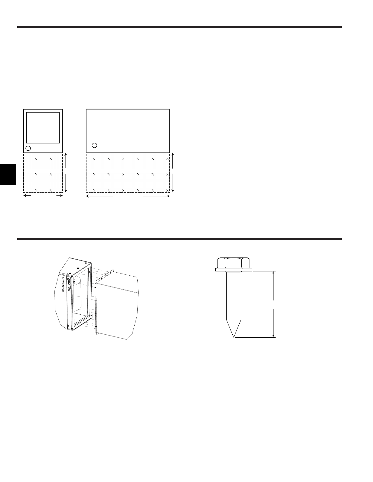
34
FR
Lacentraledetraitementd’airpeutêtreinstalléedansune
con�gurationverticale,horizontale(côté droit et côté gauche) etux
descendantcommeindiquéauxétapes9.1.à9.4.Lesappareilssont
conçuspourundégagementzéro“0”auxmatériauxcombustibles.
24poucessontnécessairespourl’accèspourl’entretienàl’avantde
l’appareil.(VoirEspacenécessaireàl’installation.)Indépendamment
delacon�gurationdemontage,lacentraledetraitementd’airdoitêtre
montéeàniveaupourfaciliterlebonécoulementdescondensats.
Espacenécessaireàl’installation
TOP View
Hor
iz
on
ta
l I
nsta
ll
ation
24"
24"
Width of Unit
TOP View
Vertica
l I
nsta
ll
ation
Le
ng
th of Unit
Clearance Area
Clearance Area
7. Installation de l’appareil
VuedeDESSUS
Installation
verticale
Zone de dégagement
VuedeDESSUS
Installation horizontale
Zone de dégagement
Largeurde
l’appareil
Longueurde
l’appareil
0.75" MAX
8. Raccordement des conduits
-Reportez-vousaudessinpourlatailledesraccordsdesconduits.
-Utilisezdesconduitsàbridepourlesraccordementsderetour.
-N’utilisezpasdevisdetôled’unelongueurdeplusde0,75”pour
�xerlesraccordsdeconduitsàlacentraledetraitementd’air.
0,75ʺMAX
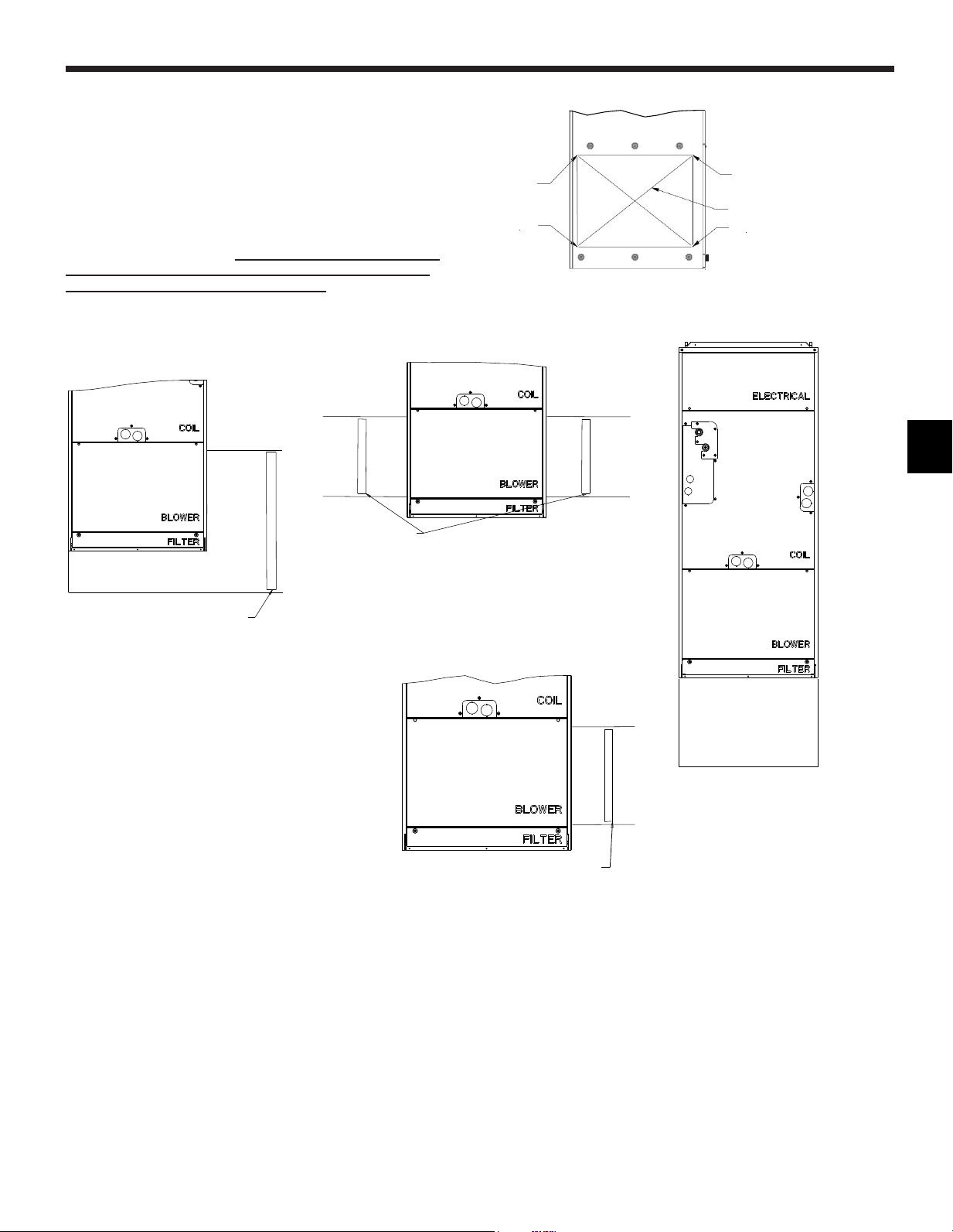
35
FR
9. Positions de montage
9.1. Installation verticale
Lacentraledetraitementd’airdoitêtresoutenueuniquementsur
lafaceinférieureetdoitêtreposéesurunesurfacesolideavecun
caissondemélangeci-dessousouuncadreoucaissondesupport
fournisurplace.Fixezsolidementlacentraledetraitementd’airau
solouaucadreoucaissondesupport.
UnretourlatéraluniquepeutêtreutilisépourPVA-A12etPVA-A18
uniquement.Lesdeuxretourslatérauxdoiventêtreutiliséssur
touslesautresmodèlespourassurerlebonécoulementdel’air.
Sileretourlatéralestutilisé,l’installateur est responsable de
s’assurer que les conduits sont de taille correcte et qu’ils
sont�xésdemanièreétancheaucaisson.Lorsdeladécoupe
surlecôtéducaisson,utilisezlesencochesfourniespournepas
endommagerlastructureinterneoulecâblage.
PLENUM
DUAL SIDE RETURN
SEAL BOTTOM OF AIR HANDLER
ADD TWO FILTERS
FILTER
PLENUM
FILTER
RETOURLATÉRAL
Encoche
Encoche
Encoche
Encoche
Conduitsderetourd’air
CAISSON
FILTRE
FILTRE
DEUXRETOURSLATÉRAUX
SCELLERLEFONDDELACENTRALEDE
TRAITEMENTD’AIR
AJOUTERDEUXFILTRES
CAISSON
FILTER
RETOURLATÉRALUNIQUE(PVA-A12,A18)
SCELLERLEFONDDELACENTRALEDE
TRAITEMENTD’AIRAJOUTERLEFILTRE
FILTRE
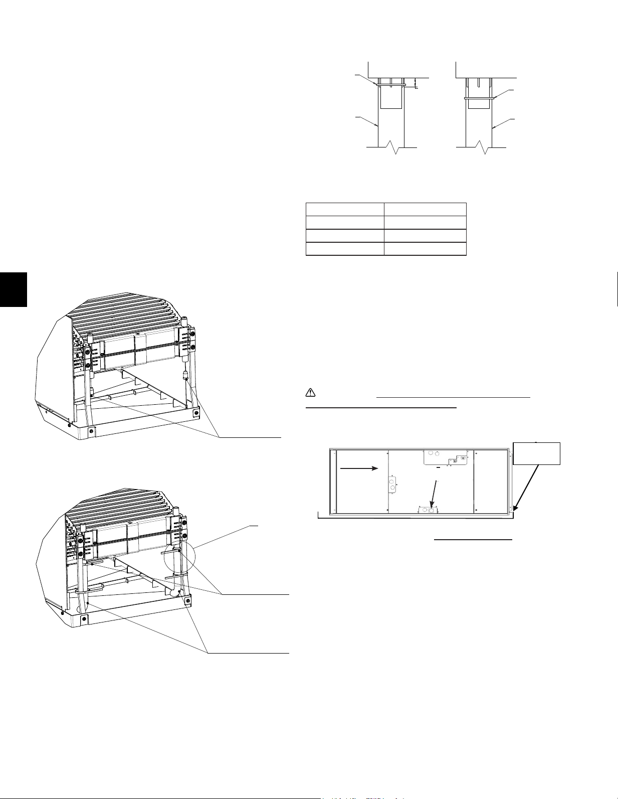
36
FR
Auxiliary
drain pan
ÉVACUATION
PRINCIPALE
3/4
”
FPT
Installation horizontale du côté droit
Larotationdublocventilateurn’estpasnécessaire.
FLUXD’AIR
9.2. Installation horizontale du côté droit
Reportez-vousàlasection9.3.Étape1à4et12pourretirer
entièrementlabobineducaissondelacentraledetraitementd’air.Il
seranécessairederetirerlespanneauxdu�ltre,duventilateur,dela
partieélectriqueetdelabobine,ainsiquelessupportsde�xationde
labobine.Veillezégalementàfairesortirles�lsdelathermistance
delapartieélectriquedelacentraledetraitementd’airdefaçonà
pouvoirretirerlabobine.
Lorsquelabobineestretirée,lesdeuxtubesenplastiquetransparent
inclusdanslesacd’accessoiresdoiventêtre�xésaubacde
récupérationsupérieur.Retirezd’abordlesbouchonsencaoutchouc
souslebacderécupérationsupérieur.Ensuite,installezlestubes
enplastiquetransparentquisontinclusdanslesacd’accessoires.
Assurez-vousquelestubesenplastiquepermettentl’évacuationdans
lebac.Véri�ezégalementquelestubesenplastiquetransparentne
comportentaucunerestriction.Ilestnécessairedecouperlestubes
enplastique,reportez-vousautableaurelatifàlalongueurdestubes.
En�n,�xezlestubesenplastiquetransparentaubacderécupération
supérieurcommeindiquéparleDétailA,puis�xez-lesauxsupports
métalliquesde�xationdelabobineaubacderécupérationsupérieur
àl’aidedesserre-câblesenplastiquefourniscommeindiqué.
Modèle Longueur de tube
PVA-A12,A18 4,9in.(125mm)
PVA-A24,30 6,9in.(175mm)
PVA-A36,42 *8,9in.(225mm)
*Longueurdetubefournie.
Réinstallezlabobineainsiquele(s)support(s)de�xation.Nepas
réinstallerlessupportsentraîneraunepertedecapacitéetlaformation
decondensationàl’intérieurducaisson.Lefaisceauélectriquepour
leconnecteurdelathermistancedoitégalementêtreacheminéà
nouveaudanslapartieélectriqueetbranchéàCN44.Reportez-vous
à9.3.Étape1à4enprocédantdansl’ordreinversepourremonterles
panneaux.Assurez-vousquelesori�cesdéfonçablesappropriéssont
retiréspourlesraccordsd’évacuationetlesconnexionsélectriques.
Précaution:
Pourl’installationhorizontale,unbacde
récupérationauxiliairedoitêtreinstallé.
5/8”
(15mm)
PLASTIC TIE
PLASTIC TUBE
PLASTIC TIE
PLASTIC TUBE
CORRECT INCORRECT
DÉTAILA
BOUCHONSEN
CAOUTCHOUC
FIXERÀL’AIDEDE
SERRE-CÂBLESEN
PLASTIQUE
2DECHAQUECÔTÉ
2TUBESENPLASTIQUE
ASSURENTL’ÉVACUATION
DANSLEBAC
VOIR
DÉTAILA
Bacde
récupération
auxiliaire
CORRECT
INCORRECT
SERRE-CÂBLEEN
PLASTIQUE
TUBEEN
PLASTIQUE
TUBEEN
PLASTIQUE
SERRE-CÂBLEEN
PLASTIQUE
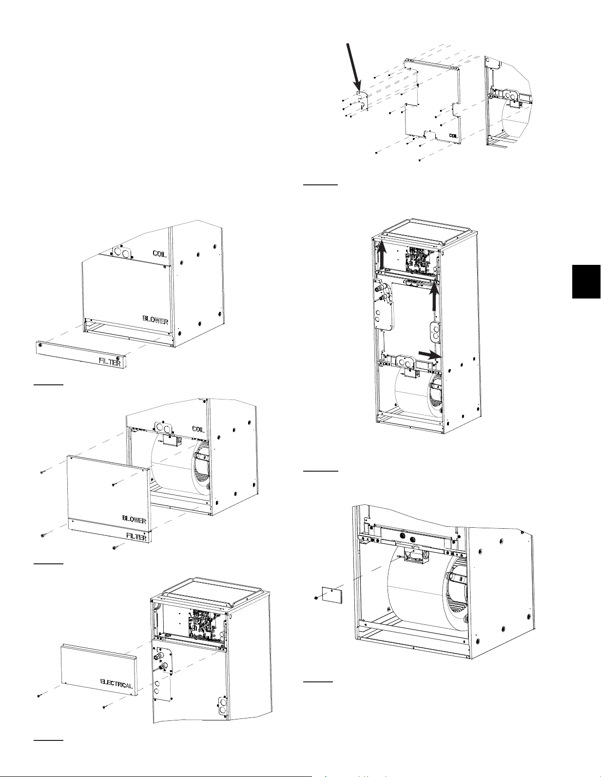
37
FR
9.3. Installation horizontale du côté gauche
Pouruneinstallationhorizontaleducôtégauche,lebacde
récupérationdoitêtredéplacéverslecôtéopposéàlabobine.Pour
cela,ilfautdéplacerlesdeuxsupportsetlebacderécupérationà
gauchedelabobine.Decettefaçon,lecondensatquis’estformé
surlabobinetomberadanslebacderécupération.Lesori�ces
défonçablesappropriéspourl’évacuationdevrontégalementêtre
retiréslorsquelebacderécupérationestdanslacorrecteposition.
Enplusdurepositionnementdubacderécupérationlatéral,ilfaut
égalementretirerleblocventilateur,lefairetournerde180°,puis
leréinstaller.Lemoteurdoitêtreleplusprochedusol.Lesdeux
tubesenplastiquetransparentinclusdanslesacd’accessoires
doiventégalementêtre�xésaubacderécupérationsupérieur.
Reportez-vousauxinstructionsci-dessous.
Instructions concernant la rotation du ventilateur pour une
installation horizontale du côté gauche :
Étape 1Retirezlepanneauportantl’inscription“FILTER”.
Étape 2Retirezlepanneauportantl’inscription“BLOWER”.
Étape 3Retirezlepanneauportantl’inscription“ELECTRICAL”.
2ème
1er
Étape 4aRetirezlesvisde�xationdespanneaux(3)aupanneau
COILcommeindiquésurl’imageci-dessus.Retirezle“1er”panneau
etle“2ème”panneauportantl’inscription“COIL”.
Étape 4bEnsuite,retirezlespetitspanneauxcouvrantlestrous
d’évacuationetlignesderéfrigérantenlesfaisantglisserd’abord
dansladirectionindiquéeci-dessus.
Étape 5Retirezlecouvercleduboîtierélectriquemontésurle
blocventilateur.Débranchezleconnecteurdumoteurainsique
leconnecteurdelathermistancederetourd’air.Retireztousles
faisceauxduboîtierélectriquepournelaisserquelathermistance
deretourd’airattachéeauboîtierélectrique.
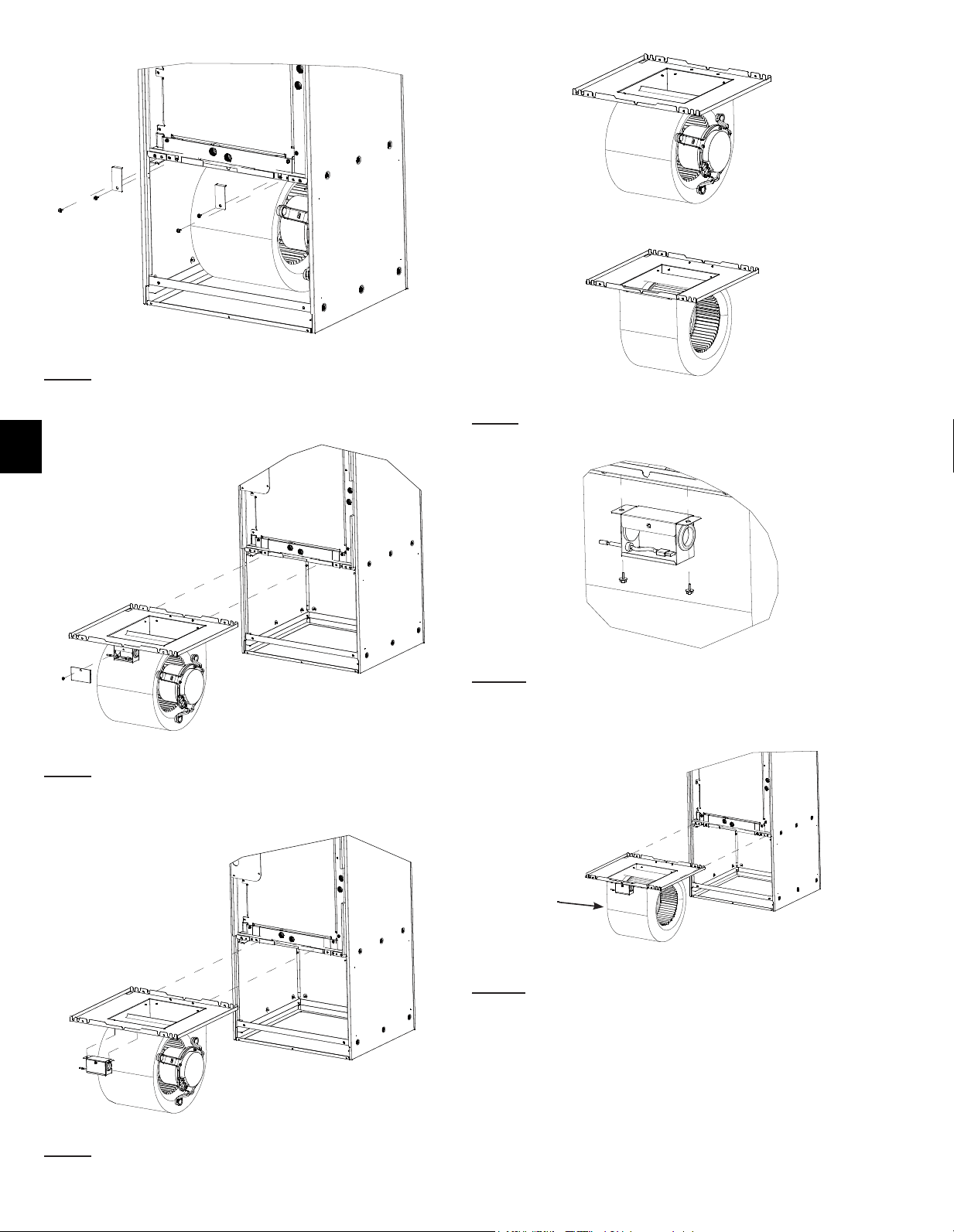
38
FR
Étape 6Retirezlesvis(4)indiquéessurl’imageainsiqueles
supportsde�xationdelabobine.
Étape 7Faitesglisserentièrementleblocventilateuretretirez-ledu
caisson.
Étape 8Retirezleboîtierélectriquedublocventilateur.
Étape 9Faitestournerleblocventilateurde180°.Lemoteurdoit
désormaissetrouversurlecôtéopposé.
Étape 10Réinstallezleboîtierducapteurdetempératuredel’airde
retoursurleblocventilateursurlecôtéopposédesonemplacement
d’origine.
MOTOR
ON
LEFT
Étape 11Remettezleblocventilateuraveclemoteurdésormaisà
gauchedanslecaissondelacentraledetraitementd’airetréutilisez
lesvis(2)pour�xerleblocventilateurenposition.Acheminez
ànouveaulesconnecteurs(2)dumoteurdansleboîtieret
rebranchez-les.
REMARQUE :Ilestpeut-êtrenécessairederetirerlefaisceau
électriquedesattachesenplastiquemontéessurlesupportdu
moteura�nd’avoirunelongueursuf�santepouratteindreleboîtier
électriquemontésurleblocventilateur.Assurez-vousquele
faisceauélectriqueest�xécorrectementetqu’ilnepeutentrer
dansleventilateur.Acheminezànouveauleconnecteurdela
thermistancederetourd’airdansleboîtierélectriqueetrebranchez-
le.
MOTEURÀ
GAUCHE
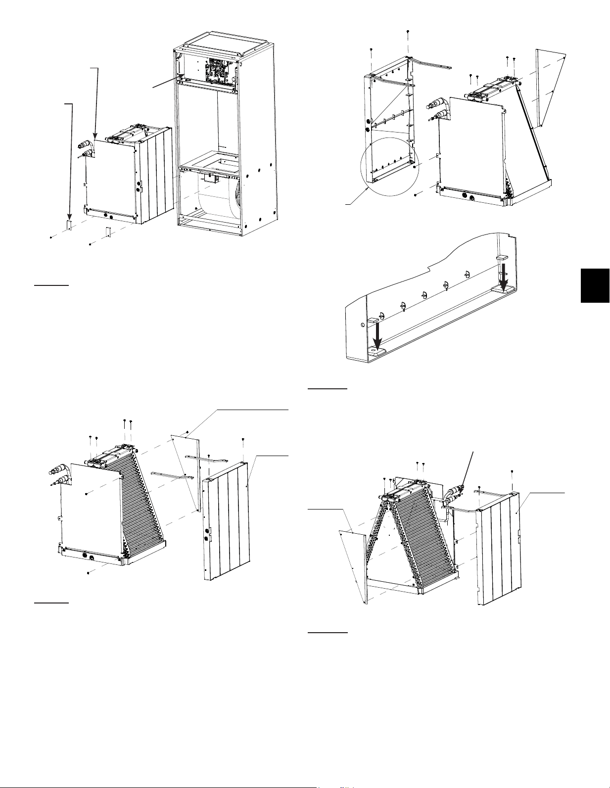
39
FR
A
C
B
Étape 12
A.Débranchezlathermistance(CN44)dupanneaudecontrôleet
faitessortirlefaisceaudelazonedelaboîtedecommandeparle
passe-câbleencaoutchouc.
B.Retirezlessupportsde�xationdelabobinesivousnel’avezpas
déjàfait.
C.Faitesglisserlabobineetretirez-laducaissondelacentralede
traitement d’air.
Étape 13Retirezlaplaqueguidearrière(3vis)etlebacde
récupérationlatéral(4vis)ainsiquelessupportsde�xation(4vis)
de la bobine.
PLAQUEGUIDEARRIÈRE
BACDE
RÉCUPÉRATION
LATÉRAL
DETAIL B
DETAIL B
Étape 14aInstallezlesjointsdubacderécupération(2)inclus
danslesacd’accessoirescommeindiquéci-dessus.Cesjoints
permettentderecouvrirlesori�cesnonutiliséssurlebacde
récupérationlatérala�nd’éviterlesfuites.
DÉTAILB
Étape 14bRéinstallezlessupportssurlecôtéopposédubacde
récupérationlatéral.Lebacderécupérationlatéralestréinstallésur
lecôtéopposédelabobine.Remettezlaplaqueguidearrièreen
placesurlecôtéopposédelabobine.
TUYAU
PLAQUE
GUIDE
ARRIÈRE
BACDE
RÉCUPÉRATION
LATÉRAL
DÉTAILB
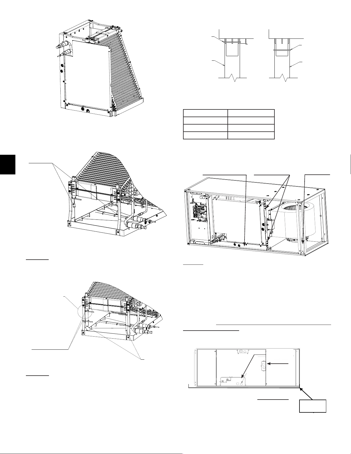
40
FR
Étape 14dEnsuite,installezlestubesenplastiquetransparent
quisontinclusdanslesacd’accessoires.Assurez-vousqueles
tubesenplastiquepermettentl’évacuationdanslebac.Véri�ez
égalementquelestubesenplastiquetransparentnecomportent
aucunerestriction.Ilestnécessairedecouperlestubesen
plastique,reportez-vousautableaurelatifàlalongueurdes
tubes.En�n,�xezlestubesenplastiquetransparentaubacde
récupérationsupérieurcommeindiquéparleDétailA,puis�xez-
lesauxsupportsmétalliquesde�xationdelabobineaubacde
récupérationsupérieuràl’aidedesserre-câblesenplastiquefournis
commeindiqué.
Étape 15Réinstallezlabobineainsiquele(s)support(s)de�xation.
Nepasréinstallerlessupportsentraîneraunepertedecapacitéet
laformationdecondensationàl’intérieurducaisson.Lefaisceau
électriquepourleconnecteurdelathermistancedoitégalement
êtreacheminéànouveaudanslapartieélectriqueetbranchéà
CN44.Reportez-vousà9.3.Étape1à4enprocédantdansl’ordre
inversepourremonterlespanneaux.Assurez-vousquelesori�ces
défonçablesappropriéssontretiréspourlesraccordsd’évacuation
etlesconnexionsélectriques.
REMARQUE :
Pourl’installationhorizontale,unbacderécupération
auxiliairedoitêtreinstallé.
Auxiliary
drain pan
MOTEUR
ENBAS
BACDERÉCUPÉRATION
LATÉRALENBAS
RATTACHERLES
SUPPORTS
ÉVACUATION
PRINCIPALE3/4
”
FPT
2SERRE-CÂBLES
ENPLASTIQUEDE
CHAQUECÔTÉ
2TUBESEN
PLASTIQUE
ASSURENT
L’ÉVACUATION
DANSLEBAC
DERÉCUPÉRATION
FLUXD’AIR
Installation horizontale du côté gauche
Larotationdublocventilateurestnécessaire.
DÉTAILA
Modèle Longueur de tube
PVA-A12,A18 4,9in.(125mm)
PVA-A24,30 6,9in.(175mm)
PVA-A36,42 *8,9in.(225mm)
*Longueurdetubefournie.
5/8”
(15mm)
PLASTIC TIE
PLASTIC TUBE
PLASTIC TIE
PLASTIC TUBE
CORRECT INCORRECT
DÉTAILA
Vue de l’étape 14b terminée de la bobine pour
l’installation horizontale du côté gauche
Étape 14c
Retirezlesbouchonsencaoutchoucindiquéssurl’imageci-dessus.
CORRECT
INCORRECT
SERRE-CÂBLE
ENPLASTIQUE
TUBEEN
PLASTIQUE
SERRE-CÂBLE
ENPLASTIQUE
TUBEEN
PLASTIQUE
Bacde
récupération
auxiliaire
BOUCHONSEN
CAOUTCHOUC
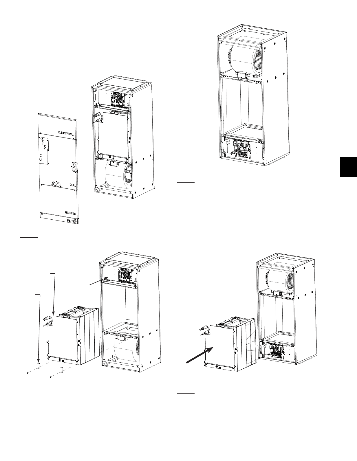
41
FR
Grâceàsaconceptioninnovanteàpositionsmultiples,l’appareil
detraitementd’airpeutpasserdesapositioninitialeàune
positionpermettantunuxdescendantsansavoirrecoursàun
ensemblestabilisationouàunraccordexterne.L’utilisationdu
uxdescendantpeutentraînerl’accumulationdecondensat.Un
ensembledegestionducondensatdevraitêtreutilisépourréduire
l’écoulementd’eau.
Étape 1Reportez-vousà9.3.Étape1à4pourleretraitdes
panneauxdelapartieélectrique,delabobine,duventilateuretdu
�ltre.
A
B
C
Étape 2
A.Débranchezlathermistance(CN44)dupanneaudecontrôleet
faitessortirlefaisceaudelazonedelaboîtedecommandeparle
passe-câbleencaoutchouc.
B.Retirezlessupportsde�xationdelabobinesivousnel’avezpas
déjàfait.
C.Faitesglisserlabobineetretirez-laducaissondelacentralede
traitement d’air.
Étape 3Faitestournerlecaissondesortequeleblocventilateur
soitenhaut.
Étape 4Remettezlabobinedanslecaisson.Iln’estpasnécessaire
derattacherle(s)support(s).
9.4.Installationenuxdescendant
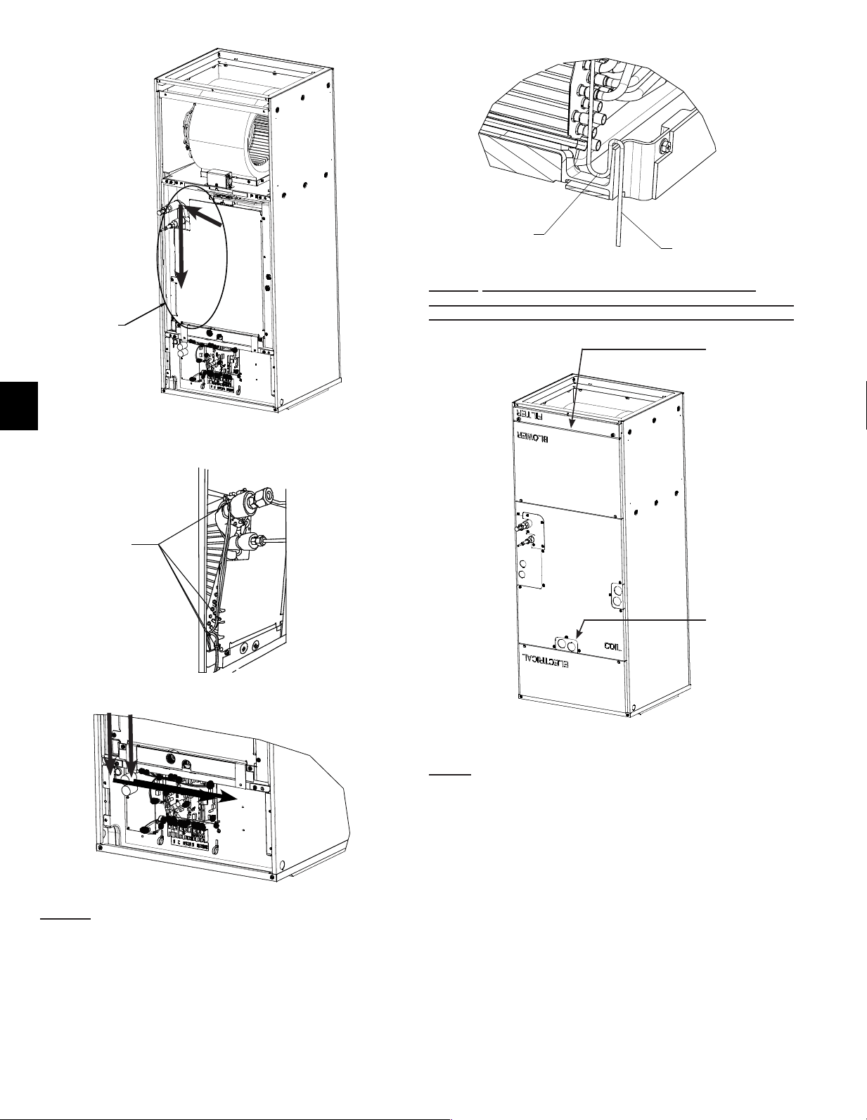
42
FR
Étape 4bCoupezlesserre-câblesenplastiquequiretiennentle
surplusdecâblesdelathermistance(CN44).Faitespasserles
�lsdelathermistancedanslapartieélectriquedelacentralede
traitementd’airducôtégauchedelabobine.
-UtilisezlapattemétalliquedansDétailApour�xerles�ls.
-L’encochedanslebacderécupérationpermetaux�lsdepasser
lebacderécupération,detraverserlaplaquedetôlequisoutient
désormaislabobineetd’entrerdanslapartieélectriquedela
centraledetraitementd’air.Rebranchezlathermistance(CN44)au
panneaudecontrôle.
Étape 4c
A�nd’empêcherl’eaudecoulersurles�lsdela
thermistance dans la partie électrique, une boucle d’égouttement
DOIT être installée pour diriger l’eau dans le bac de récupération.
3ème
1er
2ème
PATTEMÉTALLIQUE
REPLIÉEAUTOUR
DUFAISCEAU
ÉLECTRIQUE
BOUCLED’ÉGOUTTEMENT
VERSLAPARTIE
ÉLECTRIQUE
DÉTAILA
DANSLEBACDERÉCUPÉRATION
Étape 5Réinstallezlespanneauxsurlestuyauxd’écoulementet
lignesderéfrigérant.Ensuite,installezlespanneauxdelabobine
(1
er
),delapartieélectrique(2
ème
),duventilateur(3
ème
)etdu�ltre
(4
ème
).REMARQUE :Lepanneaudelabobinedoitêtreinstallé
danslebonsens,c’est-à-diredansl’orientationverticaled’origine
àlasortied’usine,tandisqueletextedesautrespanneauxseraà
l’envers.
ÉVACUATION
PRINCIPALE
3/4
”
FPT
4ème
DÉTAILA
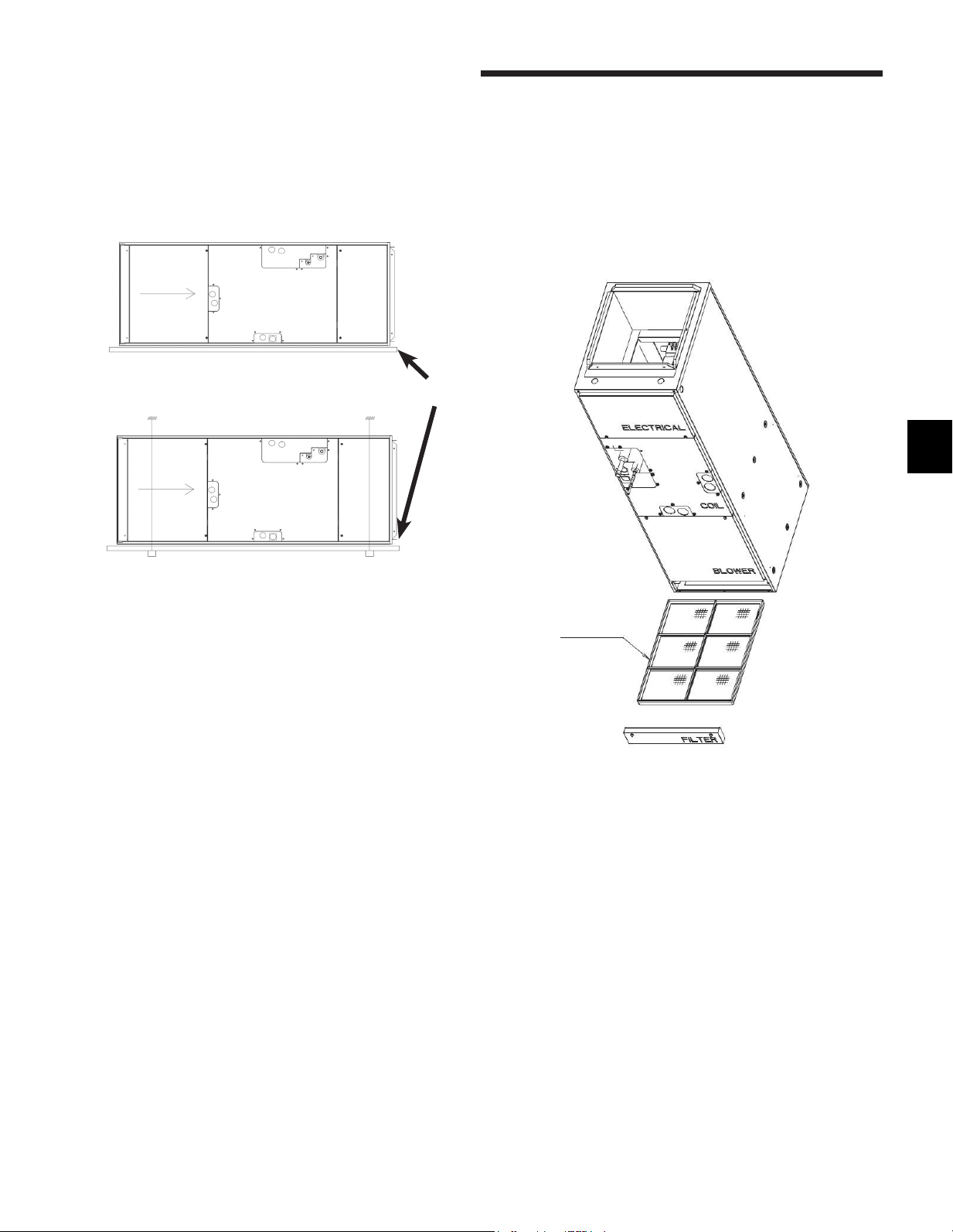
43
FR
L’appareilpeutêtreinstallésuruneplate-formeoususpenduà
desrails,commeillustréci-dessous.Lesrailsdoiventêtredela
longueurdel’appareiletd’unerésistancesuf�santepoursupporter
lepoidsdel’appareiletdesconduitsraccordés.L’isolationcontre
lesvibrationsestrecommandéepourlesinstallationshorizontales.
Certainesjuridictionspeuventexigerlemontaged’unbacde
récupérationauxiliairesousl’appareil.Respecteztoujoursles
réglementationsnationalesetlocales.
Montage horizontal
Montage sur une plate-forme
10. Filtre à air
Un�ltreàair(réutilisable)lavableestfourniaveclacentralede
traitementd’air.Le�ltrepeutêtreinstallélorsquel’appareilaété
retirédesonemballage.Ilestrecommandédenettoyerle�ltreàair
unefoisparmois.
Labaissedepressiondoitêtredéterminéeparl’installateuren
fonctiondurendementdepressionstatiqueglobaldusystème
ainsiquedelatailledesconduitsd’admissionetderetourd’air.Le
rendementdepressionstatiqueenusineestde0,50”PSE(pression
statiqueextérieure).Unchampsélectionnablede0,30et0,80PSE
estdisponible.Reportez-vousauxinstructionspourchangersur
0,30ou0,80PSEdanslapartieélectrique(13.4.).
BACDE
RÉCUPÉRATION
AUXILIAIRE
Montage suspendu
FILTRE
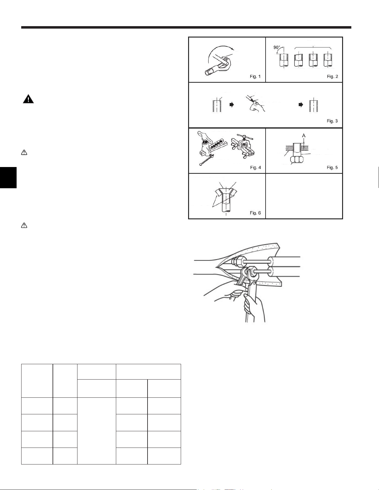
44
FR
11. Mise en place des tuyaux de réfrigérant
Pourlesrestrictionsdelongueurdestuyauxetledegréd’élévationpermis,
reportez-vousàlasectionsurlaconceptiondumanueld’ingénierie.
Laméthodederaccordementdestuyauxdelacentralede
traitementd’airsefaitavecdesraccordsévasés.
Placezuneentretoiseappropriéepourlestuyauxderéfrigérant
detellesortequ’aucunechargenes’appliqueauxraccordsdela
centraledetraitementd’air.
Avertissement :
Lorsdel’installationetdudéplacementdel’appareil,ne
lechargezpasavecunréfrigérantautrequeceluispéci�é
surl’appareil.
Lemélanged’unautreréfrigérant,d’air,etc.peut
provoquerunmauvaisfonctionnementducyclede
réfrigérationetentraînerdegravesdommages.
Précaution :
Utilisezdestuyauxderéfrigérationencuivredésoxydé
auphosphoreC1220(Cu-DHP)commeindiquéparla
normeASTMB280pourlestuyauxettubesencuivreou
enalliagedecuivresanssoudure.Veillezégalementàce
quelessurfacesinternesetexternesdestuyauxsoient
propresetdépourvuesdesoufre,d’oxydes,depoussière/
impuretés,derognures,d’huile,decondensationoude
touteautreparticulecontaminante.
N’utilisezjamaislestuyauxderéfrigérantdéjàenplace.
Précaution : BOBINE SOUS PRESSION
Portez toujours des lunettes de sécurité lorsque vous faites
des travaux à proximité de dispositifs sous pression.
Les centrales de traitement d’air sont livrées avec une charge
d’attente d’azote présente dans la bobine. Suivez attentivement
ces instructions lors de la libération de la charge.
Retirezsoigneusementl’écrouévaséàl’extrémitédutuyaupour
libérertoutgaz.
Lesdeuxlignesderéfrigérantdoiventêtreisoléesjusqu’aucaisson.
Assurez-vousquelesouverturesdanslecaissonautourdeslignes
deréfrigérantsontcouvertes.L’épaisseurminimalerecommandée
pourl’isolationestde3/8depouces.Selonlesconditions
ambiantes,lesréglementationslocalesetlalongueurdeligne,une
isolationplusépaissepeutêtrenécessaire.
Nemettezpasd’huilesurlapartie�letéedesécrousévasés.Celapourrait
entraînerundesserrementdel’écrouévaséetunefuitederéfrigérant.
Diamètre
detuyau
pouce(mm)
Écrou
(mm)
Apouce(mm) Coupledeserrage
Outildetype
d’embrayage
pourR410A
N•m
lb•ft
(kgf•cm)
1/4(6,35) (17)
0à0,02
(0à0,5)
13,7à17,7
10à13
(140à180)
3/8(9,52) (22) 34,3à41,2
25à30
(350à420)
1/2(12,7) (26) 49,0à56,4
36à42
(500à575)
5/8(15,88) (29) 73,5à78,4
54à58
(750à800)
-N’utilisezjamaislestuyauxderéfrigérantdéjàenplace.
-Laquantitéimportantedechlorecontenuedanslesréfrigérants
traditionnelsetl’huilederéfrigérationdestuyauxactuelsprovoquera
ladétériorationdunouveauréfrigérant.
-Gardezlestuyauxàutiliserpourl’installationàl’intérieuretlaissez
lesdeuxextrémitésdestuyauxcouvertesjusqu’aumomentdu
brasage.
-Sidelapoussière,delasaletéoudel’eaus’in�ltredanslecycle
deréfrigération,l’huilesedétérioreraetlecompresseurrisquede
tomber en panne.
-Appliquezunepetitequantitéd’huiled’ester,d’huiled’étherou
d’alkylbenzènecommehuilederéfrigérationsurlesévasementset
lesconnexionsàbridesavantd’effectuerlesraccordements.
-Leréfrigérantutilisédansl’appareilestextrêmement
hydroscopiqueetnedoitpasêtremélangéavecdel’eau,autrement
l’huilederéfrigérationsedétériorera.
Tuyauen
cuivre
Correct
Incorrect
Incliné Inégal Bavure
Bavure
Tuyauencuivre
Alésoirsupplémentaire
Coupe-tuyaux
Outild’évasement
Typed’em-
brayage
Typed’écroupapillon
Étau
Écrouévasé
Tuyauencuivre
Lissetoutautour
Lamêmelon-
gueurpartout
L’intérieurbrille
et n’est pas
rayé.
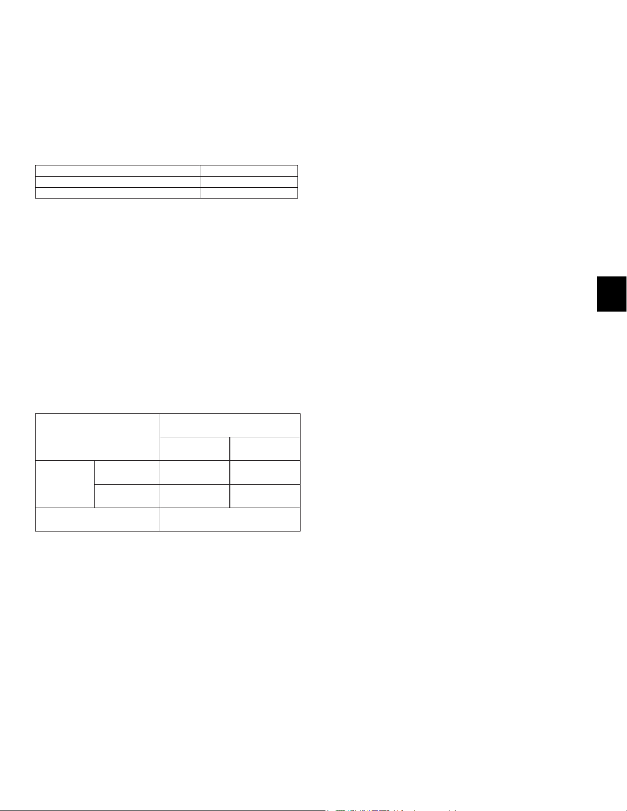
45
FR
11.1. Isolation
Pouréviterlesgouttesdecondensation,appliquezsuf�sammentde
matériauxisolantsanti-condensationsurlestuyauxderéfrigérant
etd’écoulement.Encasd’utilisationdetuyauxderéfrigérant
disponiblesdanslecommerce,assurez-vousdecouvrirlestuyaux
degazetdeliquideavecdesmatériauxisolantsd’unetempérature
derésistanceàlachaleurdeplusde100°C[212°F]etd’une
épaisseurconformeàcelledonnéeci-dessous.Isoleztousles
tuyauxintérieursavecunisolantenpolyéthylèneprésentant
unedensitéminimalede0,03etuneépaisseurconformeaux
recommandationsdutableauci-dessous.
Tailledestuyaux Épaisseurdel’isolant
6,4à25,4mm[1/4à1in.] >10mm[7/16in.]
28,6à38,1mm[1-1/8à1-1/2in.] >15mm[5/8in.]
-Sil’appareilestutiliséaudernierétaged’unimmeubleetqu’ilest
soumisàdestempératuresélevéesetàunehumiditéexcessive,il
convientd’utiliseruneisolationplusépaissequecelleindiquéedans
letableauci-dessus.
-Veuillezrespecterlesspéci�cationstechniquesdel’utilisateur,le
caséchéant.
11.2. Taille des tuyaux
Modèle
PVA-AA7
12-18 24-30-36-42
Tuyaude
réfrigérant
Tuyaude
liquide
6,35mm[1/4] 9,52mm[3/8]
Tuyaude
gaz
12,7mm[1/2] 15,88mm[5/8]
Tuyaud’écoulement Diam.ext.32mm[1-1/4]
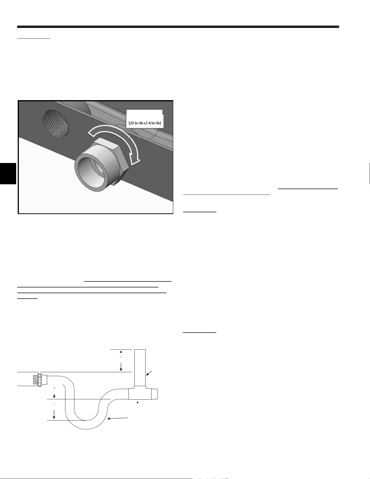
46
FR
IMPORTANT !
Un serrage excessif des raccords d’évacuation pourrait
endommager et entraîner une panne du bac de récupération.
Suivezlaprocéduresuivantepour�xerl’adaptateurdubacde
récupération:
1.Appliquerunepâted’étanchéitépourraccords�letésapprouvée
pourlesplastiques.
2.Serrezl’adaptateurdubacderécupérationàuncouplede2,5
Nm+/-0,5[22in-lb].
Lacentraledetraitementd’aircomportedesraccordsd’évacuation
de¾”FPT.Lorsquel’appareilestutiliséenpositionverticale,ily
enaunensemble.Lorsquel’appareilestmontéhorizontalement,
ilyenaunensemble.Chaqueensemblecontientuneévacuation
principaleetuneévacuationsecondaireouauxiliaire.L’évacuation
principaleestl’évacuationlaplusbasse(mêmeaveclebasdu
bac).L’évacuationsecondaireestauniveauleplushaut.Ellessont
indiquéessurleplandimensionnelci-dessus.
-Cesappareilsfonctionnentavecunepressionpositiveauniveau
desraccordsd’évacuationetmême si un siphon horizontal n’est
pas nécessaire, il est recommandé pour éviter la perte de
capacité. Respectez toujours les normes et réglementations
locales.
-Lesiphondoitêtreinstalléleplusprèspossibledel’appareil.
Assurez-vousquelehautdusiphonestau-dessousduraccordau
bacderécupérationpourpermettrel’évacuationcomplètedubac.
-Inclinezlaligned’évacuationdeminimum¼”parpied.
-Neréduisezlatailledutuyaude¾”,celapourraitentraînerune
obstructionprématuréedansleslignes.
-Nesoudezpasàproximitédestuyauxd’écoulementenplastique.
2" Min.
Anti-syphon
air vent
2" Min.
2" Min.
Vent T
Drain Trap
Remarque :
Lesconduitshorizontauxdoiventégalementavoir
unanti-siphonavecévent(colonnemontante)installéau-dessus
duconduithorizontalpouréliminerlepiégeagedel’air.Leslignes
d’évacuationhorizontalesdoiventavoiruneinclinaisondeminimum
¼”parpied.
Acheminezleslignesd’évacuationàl’extérieurouversune
évacuationappropriée.Leslignesd’évacuationdoiventêtre
installéesdefaçonànepasbloquerl’accèspourl’entretienàl’avant
del’appareil.Undégagementde24”àl’avantestnécessairepourla
maintenanceoul’entretienderoutine.
Remarque :
Véri�ezlesréglementationslocalesavantde
raccorderlaligned’évacuationàunsystèmed’évacuationexistant.
Isolezleslignesd’évacuationauxendroitsoùlacondensationpeut
causerdesdégâtsd’eau.
Lorsquel’installationestterminée,l’installateurestresponsable
des’assurerquele(s)bac(s)derécupérationattrape(nt)tousles
condensats,etquetouslescondensatssontévacuéscorrectement
etqu’ilsnepénètrentpasdanslesconduits/lesystème.
Montage vertical :
Lorsdumontagevertical,leraccordd’évacuationprincipalede
lacentraledetraitementd’airsetrouveaucentredel’appareil.
L’évacuationlégèrementplushauteàgaucheestl’évacuation
secondaire.
Fixezleraccordd’évacuationetserrez-leAU COUPE APPROPRIÉ
COMME INDIQUÉ PRÉCÉDEMMENTavecdumasticetinstallezla
ligned’évacuation.
IMPORTANT !
Un serrage excessif du raccord d’évacuation pourrait
endommager et entraîner une panne du bac de récupération.
Leraccordsecondairedoitêtreraccordéàunsystèmed’évacuation
séparé.Utilisezl’évacuationsecondairepourpouvoirconstater
l’écoulementdel’eaudansl’évacuationsecondaireindiquant
uneobstructiondansl’évacuationprincipale.Uninterrupteurde
débordementdeligned’évacuationprincipale(fourniparuntiers)
peutêtreutiliséfacultativementpourl’évacuationsecondaire.Ce
dispositifarrêtelefonctionnementdel’appareilderefroidissement
encasd’obstructiondansl’évacuationprincipale.Reportez-vousà
lasectionsurlecâblagepourlebranchementdecedispositif.
Montage horizontal (côté droit ou côté gauche) :
Sil’appareilestinstalléhorizontalement,retirezl’ori�cedéfonçable
surlepanneauavantpourpouvoiraccéderauxraccordsdubacde
récupérationlatéral.Fixezleconnecteurcomme indiqué ci-dessus
etacheminezlaligned’évacuation.Touteslesouverturesdubacde
récupérationverticaldoiventêtrerecouvertespouréliminerlaperte
d’airquientraîneunediminutiondelacapacitédel’appareil.
IMPORTANT !
Un serrage excessif du raccord d’évacuation pourrait
endommager et entraîner une panne du bac de récupération.
Leraccordsecondairedoitêtreraccordéàunsystèmed’évacuation
séparé.Utilisezl’évacuationsecondairepourpouvoirconstater
l’écoulementdel’eaudansl’évacuationsecondaireindiquant
uneobstructiondansl’évacuationprincipale.Uninterrupteurde
débordementdeligned’évacuationprincipale(fourniparuntiers)
peutêtreutiliséfacultativementpourl’évacuationsecondaire.Ce
dispositifarrêtelefonctionnementdel’appareilderefroidissement
encasd’obstructiondansl’évacuationprincipale.Reportez-vousà
lasectionsurlecâblagepourlebranchementdecedispositif.
12. Raccords d’évacuation
2,5Nm+/-0,5Nm
[22in-lb+/-4in-lb]
2" min.
2" min.
2" min.
Anti-siphon
avecévent
ÉventenT
Siphond’évacuation
47
FR
13. Câblage électrique
Avertissement :
Les travaux électriques doivent être menés à bien par
desélectriciensquali�és,conformémentaux“normesde
réglementation d’installation électrique” et aux explications
données dans les manuels d’installation. Si l’installation
électriquen’estpassuf�sammentpuissanteousiellen’est
pas conforme, elle peut présenter un risque d’électrocution
ou d’incendie.
− Veuillezrespecterlesréglementationsnationaleset
localeslorsducâblagedecesappareils.
− Installezl’appareildesortequ’aucundescâblesducircuit
decommande(câblesdelacommandeàdistance,de
transmission)n’entreencontactdirectaveclecâble
d’alimentationsituéàl’extérieurdel’appareil.
− Véri�ezqu’iln’yapasdetensionauniveaudes
raccordementsdescâbles.
− Certainscâbles(d’alimentation,delacommandeà
distanceoudetransmission)situésau-dessusduplafond
peuventêtreendommagésaccidentellementoupardes
animaux.Utilisezdesconduitsautantquepossiblea�n
d’évitercela.
− Neraccordezjamaislecâbled’alimentationàdesbornes
pourcâblesdetransmission.Lescâblesrisquentdese
rompre.
− Assurez-vousderaccorderlescâblesdecommandes
àl’appareilintérieur,àlacommandeàdistanceetà
l’appareilextérieur.
− Effectuezlecâblageconformémentauxrèglesdesécurité
détailléesdansUL1995.
− Assurez-vousd’installerundisjoncteurdefuitedeterre
surl’alimentation.
− Installezl’appareildesortequ’aucundescâbles
ducircuitdecommande(câblesdelacommandeà
distance,detransmission)n’entreencontactdirect
aveclecâbled’alimentationsituéàl’extérieurde
l’appareil.
− Véri�ezqu’iln’yapasdejeuauniveaudetousles
raccordementsdescâbles.
− Certainscâbles(câblesd’alimentation,dela
commandeàdistance,detransmission)situésau-
dessusduplafondrisquentd’êtrerongésparlessouris.
Utilisezautantdetuyauxmétalliquesquepossiblepour
yintroduirelescâblesenvuedelesprotéger.
Précaution :
Veillez à mettre l’appareil à la terre. Ne raccordez pas
le câble de mise à terre à un tuyau de gaz ou d’eau,
à un paratonnerre ou un câble de terre téléphonique.
Une mauvaise mise à la terre peut constituer un danger
d’électrocution.
Si le cordon d’alimentation est endommagé, il doit être
remplacé par le fabricant, un agent d’entretien ou une
personnequali�éedemanièreàévitertoutrisque.
Spéci�cationsd’entrée/sortieexterne
Précaution :
Les câbles doivent être recouverts d’une gaine isolante
avec une isolation supplémentaire.
Utilisez des relais ou des interrupteurs répondant aux
normes CEI ou équivalentes.
La puissance électrique entre les éléments accessibles et le
circuit de commande doit être de 2750 V minimum.
Câblage
Le câblage électrique de la centrale de traitement d’air
provient de l’appareil extérieur. Reportez-vous aux
instructions d’installation de l’appareil extérieur.
Précaution :
N’ALIMENTEZ PAS LE CHAUFFAGE ÉLECTRIQUE DE-
PUIS L’APPAREIL EXTÉRIEUR. SUIVEZ LE SCHÉMA
DE CÂBLAGE APPROPRIÉ QUI FIGURE DANS LES
INSTRUCTIONS DU CHAUFFAGE ÉLECTRIQUE.
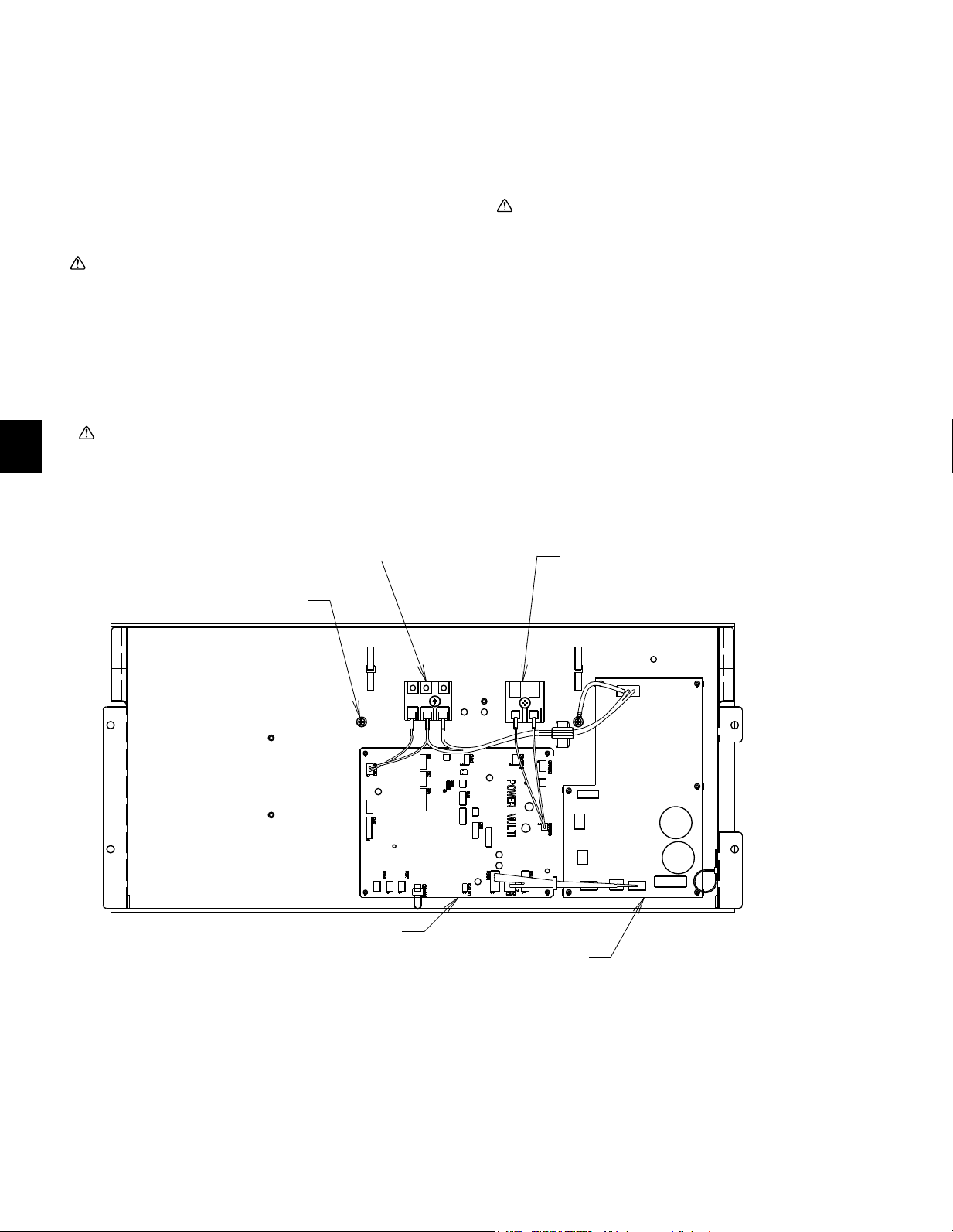
48
FR
13.1. Commandes à distance
Raccordement des câbles de la commande à distance
et des câbles de transmission intérieurs et extérieurs
Connectezlespoints“1”et“2”delaborneTB15del’appareil
intérieuràunecommandeàdistance.(Câblebi�lairenonpolarisé)
Remarque :
Assurez-vousquelescâblesnesontpascoincéslorsdumontage
ducouvercleduboîtieràbornes.Coincerlescâblespourraitles
couper.
Précaution :
Installezlescâblesdesortequ’ilsnesoientpastendusousous
tension.Lescâblessoustensionpeuventeneffetserompreou
chaufferetbrûler.
Fixezlescâblesd’alimentationàlaboîtedecommandeàl’aide
decollierstamponsouenforçant.(EffectuezuneconnexionPG
ousimilaire.)Raccordezlescâblesdetransmissionaubornierde
transmissionparl’ori�cedéfonçabledelaboîtedecommandeà
l’aidedecolliersordinaires.
Lorsquelecâblageestterminé,véri�ezànouveauqu’iln’yapas
detensionauniveaudesraccordementset�xezlecouvercle
surlaboîtedecommandeenprocédantdansl’ordreinversedu
démontage.Couvrezégalementtouteslesouverturescrééeslorsdu
câblagedanslacentraledetraitementd’air.Celapermettrad’éviter
lesfuitesd’air.
Précaution :
Câblezl’alimentationdesortequ’aucunetensionnesoitexercée.
Danslecascontraire,unedéconnexion,unesurchauffeouun
incendiepourraitseproduire.
Important :
Branchezlecâbleblindédeterreàlabornedeterredel’appareil
extérieur.
Silecâbledelacommandeàdistancedépasse10m[32ft.],utilisez
uncâblede1,25mm
2
[AWG16]dediamètresurlasectiondépassée
etajoutezcettesectiondépasséeàmoinsde200m[656ft.].
Précaution :
N’utilisezquedesdisjoncteursetdesfusiblesdecapacité
correcte.L’utilisationdefusibles,de�lsoude�lsencuivreà
tropgrandecapacitépeutprovoquerunrisquedemauvais
fonctionnementoud’incendie.
BORNEDETERRE
PANNEAUDECONTRÔLE
PANNEAUDEL’ONDULEUR
VERSLACOMMANDEÀDISTANCE
1,2
S1,S2,S3
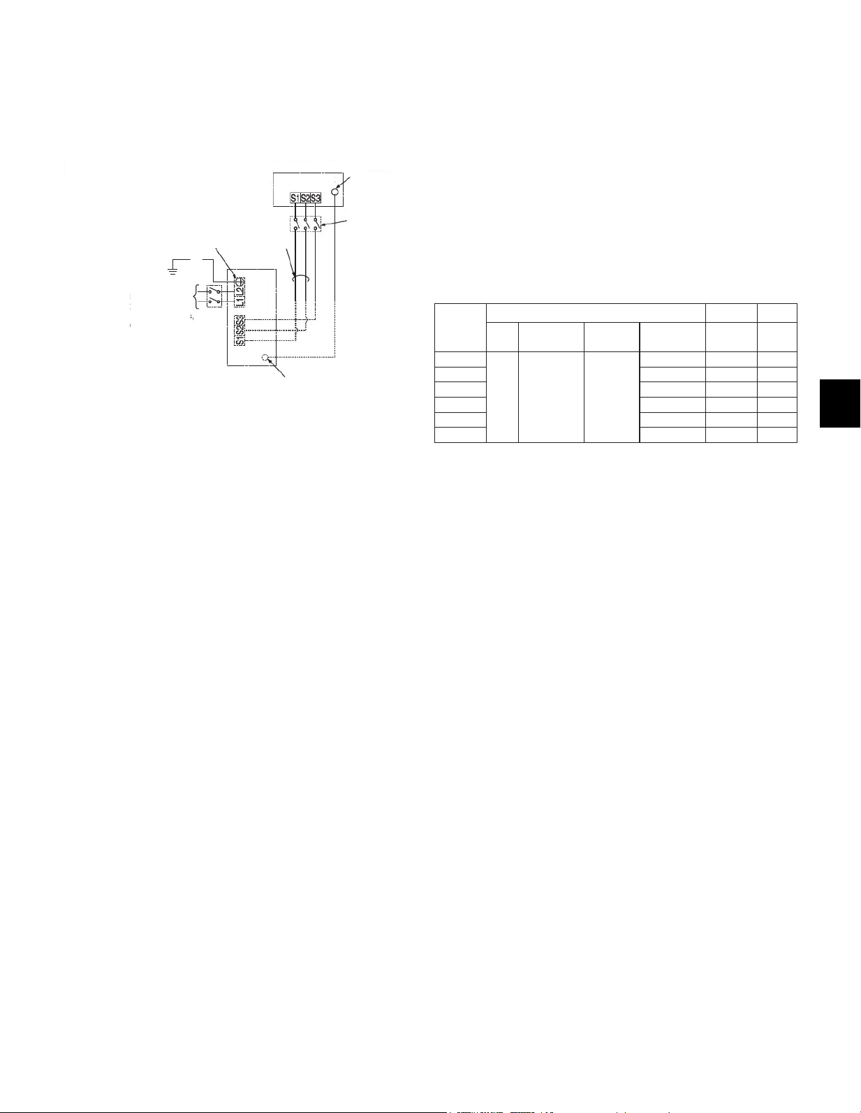
49
FR
13.2. Raccordement à la tension de ligne
Assurez-vous que l’alimentation est coupée.
L’unité doit être installée par un entrepreneur/électricien agréé.
Un interrupteur devra être installé lorsque l’unité intérieure est
alimentée par l’unité extérieure, si les lois nationales, étatiques
et locales le requièrent.
REMARQUE : Si la centrale de traitement d’air est installée
avec un ensemble de chauffage électrique, n’alimentez pas le
chauffage électrique depuis l’appareil extérieur.
Tout câblage doit être conforme aux réglementations nationales
et locales.
1.
Retirezl’ori�cedéfonçablesouhaitésurlacentraledetraitementd’air.
2.Fixezleraccorddutuyausurlacentraledetraitementd’airet
acheminezlescâblescommeindiquésurleschémaci-dessus.
Assurez-vousquel’ori�ceduraccorddutuyauestétancheàl’airet
ajoutezdumasticsinécessaire.
3.Serrezfermementtouteslesvisdesbornes.Aprèslesavoir
serrées,véri�ezqueles�lssontbien�xés.
Caractéristiques électriques
Symboles:MCA:Ampèresmax.ducircuit(=1,25×FLA)FLA:Courantàpleinecharge
IFM:MoteurduventilateurintérieurSortie:Sortienominaledumoteurduventilateur
Modèle
Appareilintérieur
Hz Volts
Plage de
tension
MCA
(A)
Sortie
(kW)
FLA
(A)
A12
60
208/230 V
188à
253 V
3,00/3,00 0,121 2,4
A18 3,00/3,00 0,121 2,4
A24 4,13/4,13 0,244 3,3
A30 4,13/4,13 0,244 3,3
A36 5,5/5,5 0,430 4,4
A42 5,63/5,63 0,430 4,5
Bornedeterre*
Remarque:
* Utilisezunecosseàplageronde
a�nderelierun�ldeterreàla
borne.
APPAREILINTÉRIEUR
APPAREIL
EXTÉRIEUR
Sectionneur
Bornedeterre*
Bornede
terre*
Alimentation
208/230VCA,
monophasé
bi�laire,60Hz
Miseàlaterre
208/230VCA,
monophasé,60Hz
Bornier
Bornier1
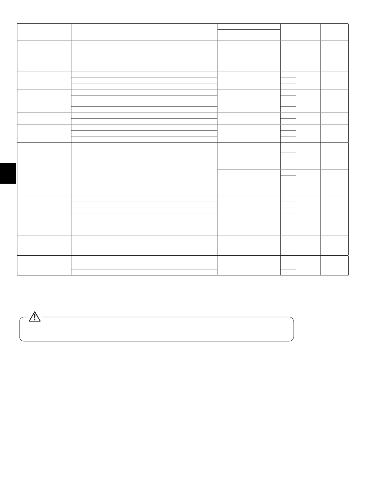
50
FR
Tableau des fonctions
Mode Réglages
N°demode(fonction)
N°de
ré-
glage
Réglage
initial
Véri�cation
Commandeàdistancecâblée
(ThermostatRF)
Redémarrage
automatiqueaprèsune
coupuredecourant
Nondisponible
01
(101)
1
1
Disponible 2
Détectiondela
températureintérieure
Moyennedefonctionnementdel’appareilintérieur
02
(-)
1
1Réglageparlacommandeàdistancedel’appareilintérieur 2
Capteurinternedelacommandeàdistance 3
ConnectivitéLOSSNAY
Nonsupportée
03
(103)
1
1
Supportée(l’appareilintérieurn’estpaséquipéd’uneprised’air
extérieure)
2
Supportée(l’appareilintérieurestéquipéd’uneprised’airextérieure) 3
Tension
d’alimentation
240V(230V)
04
(104)
1
1
220V(208V) 2
Symbolede�ltre
100 h
07
(107)
1
32500 h 2
“Pasd’indicateurdesymbolede�ltre” 3
Pressionstatique
extérieure
Reportez-vousàlasection13.4
aumanueld’installation
08
(108)
1
2
2
3
10
(110)
1
1
2
Contrôlede
l’humidi�cateur
OpérationdechauffageetThermoactif
16
(116)
1
1
Opérationdechauffage 2
l’humidi�cateur
l’humidi�cateurabsent
13
(113)
1
1
l’humidi�cateurpresent 2
Commandedechauffage
Radiateurabsent
11
(111)
1
1
Radiateurpresent*1 2
Commandedechauffage
pendantledégivrageou
situationd’erreure
Radiateurhors-servicependantdégivrageousituationd’erreur
23
(123)
1
1
Radiateuretfanactivéspendantdégivrageetsituationd’erreure*2 2
Vitessedeventilation
opérationdechauffage
etthermoinactif
Extrabasse
25
(125)
1
1ARRÊT 2
Réglage RC 3
Vitessedeventilation
opération de refroidisse-
mentetthermoinactif
Réglage RC
27
(127)
1
1
ARRÊT 2
*1Pendantqueleradiateurfonctionne,leventilateurvaopéreravitesseélevéindépendammentdesesparamètressurlatélécommande
*2Leradiateurnefonctionnerapaspendanttouteslessituationsd’erreurs.Leradiateurvaseulementopérerlorsd’unproblèmedecommunication
entrel’unitéintérieuretextérieur
Note:LorsqueleCN4YestconnectéleventilateurseraferméetquandCN24estouvertilserautiliséseulementpourlachaleuradditionnelleà
l’extérieurduconduit.
* Si un radiateur est installé dans le conduit, ne pas utiliser le connecteur de panneau chauffant.
Le ventilateur s’éteindrait conséquemment à l’ouverture du radiateur pouvant conduire à des risques de feu.
-Reportez-vousàlasection13.4.pourlesréglagesdelapressionstatiqueextérieure.
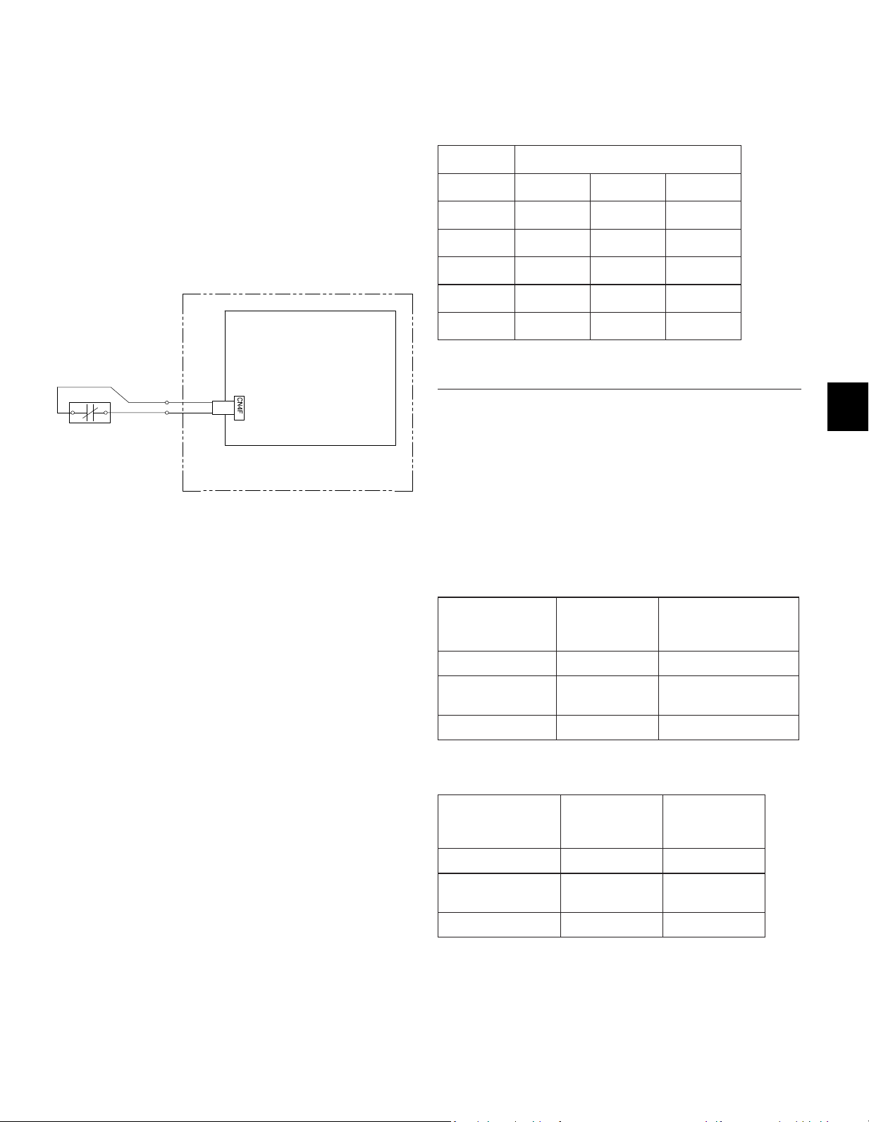
51
FR
13.3. Connexion de l’interrupteur de sécurité de dé-
bordement de condensat (CN4F)
Lacartedecircuitestéquipéed’uneconnexionpour�xerun
interrupteuràotteurdesécuritédecondensat.L’interrupteurdoit
êtreuninterrupteurnominalbassetensionnormalementfermé.
L’interrupteurdoitêtreinstallédansunendroitoùilpeutdétecter
uneobstructiond’évacuationprovoquantunehausseduniveau
d’eau.Cetteélévationduniveaud’eauentraînerasonouverture.
L’emplacementdel’interrupteurdoitêtredéterminéparl’installateur.
Lorsquel’interrupteurs’ouvre,celaentraînelafermetureduLEV
etl’arrêtdel’opérationderefroidissement.Leventilateurcontinue
defonctionneretuncoded’erreurs’af�cherasurlacommandeà
distance.Lacorrectionduproblèmeetlafermeturedel’interrupteur
sontnécessairesavantlareprisedufonctionnementnormal.
Reportez-vousàl’installationci-dessous:
13.4.Modi�cationdelapressionstatiqueextérieure
(PSE) du ventilateur
Lacentraledetraitementd’airestéquipéed’unréglagedela
pressionstatiqueajustable.Lesréglagesdisponiblessontindiqués
dansletableauci-dessous.
Modèle PSE [in. WG] disponible
PVA-A12 0,30 0,50 0,80
PVA-A18 0,30 0,50 0,80
PVA-A24 0,30 0,50 0,80
PVA-A30 0,30 0,50 0,80
PVA-A36 0,30 0,50 0,80
PVA-A42 0,30 0,50 0,80*
*PressionstatiqueextérieurepourPVA-A42enuxdescendant:0,70
La centrale de traitement d’air est réglée sur 0,50 PSE en usine.
Lapressionstatiquedelacentraledetraitementd’airpeutêtre
modi�éedanslesréglagesdemode/desfonctionsdelacommande
àdistance.Reportez-vousaumanueld’installationdelacommande
àdistancepourensavoirplussurlamodi�cationdecetteoption.
Selonlacommandeàdistanceutilisée,lemode/lafonctionestsoit
08pourlemode(PAR-31etMAsimple)ou108pourlafonction
(MHK1).Veuilleznoterquelesréglagessontdifférentslorsde
l’installationdelacentraledetraitementd’airenpositiondeux
descendant.
Réglage de la pression statique extérieure pour l’installation
verticale, horizontale du côté gauche, horizontale du côté
droit
Pression statique
extérieure
N° de réglage
de mode/
fonction 08/108
N° de réglage de
mode/fonction 10/110
(Réglage d’usine)
0,3in.WG[75Pa] 1 1
0,5in.WG[125Pa]
(Réglage d’usine)
2 1
0,8in.WG[200Pa] 3 1
Réglage de la pression statique extérieure pour l’installation
enuxdescendant
Pression statique
extérieure
N° de réglage
de mode/
fonction 08/108
N° de réglage
de mode/
fonction 10/110
0,3in.WG[75Pa] 1 2
0,5in.WG[125Pa]
(Réglage d’usine)
2 2
0,8in.WG[200Pa]* 3 2
*PressionstatiqueextérieurepourPVA-A42enuxdescendant:0,70
RepérezleconnecteurCN4Fsur
lepanneaudecontrôle.Retirez
soigneusementleconnecteuravec
lecavalierdupanneau.Coupezle
cavaliersurleconnecteurCN4Fet
câblezuninterrupteuràotteurde
sécuriténormalementferméentre
les�ls.Réinstallezsoigneusement
leconnecteursurlepanneau.
Lorsquel’interrupteuràotteur
normalementfermés’ouvre,
l’appareilintérieurs’arrête.
Panneaudecontrôledansla
centraledetraitementd’air
Centrale de traitement d’air
Interrupteuràotteur
normalement fermé
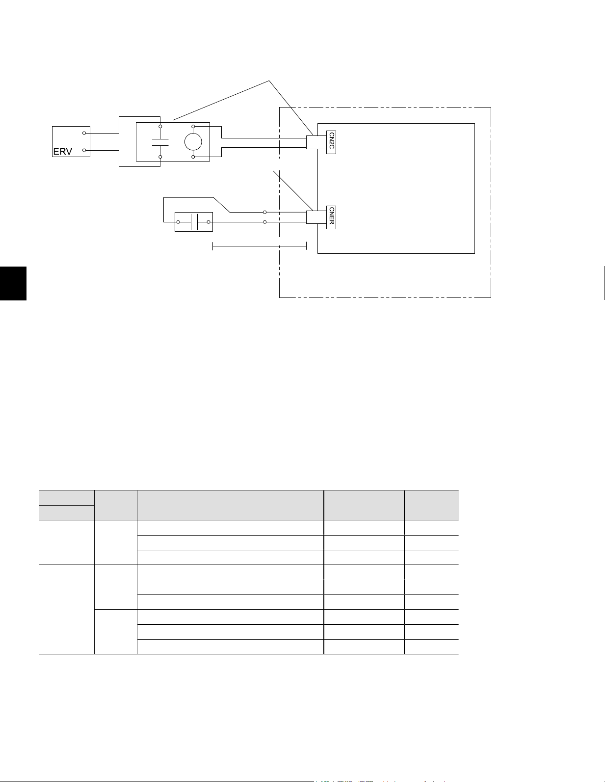
52
FR
13.5. Ventilation avec récupération d’énergie (ERV)
Séquencedefonctionnement:
1.L’interrupteurdelademandeERVfermeCNER.
2.12VCCestfourniàCN2Cpouractiverlaventilationavecrécupérationd’énergie.
3.Sil’appareilpasseendégivrage,CN2Carrêtelasortiede12VCC.
InterrupteurERV:
EntréeducontactAsanstension
Tensionnominaleducontact>=15VCC
Courantnominalducontact>=0,1A
Chargeminimaleapplicable<=1mAenCC
Contrôle de la ventilation avec récupération d’énergie
Numérodepièce:CN24RELAY-KIT-CM3
Panneaudecontrôledansla
centraledetraitementd’air
Centrale de traitement d’air
max 30 ft.
InterrupteurERV(sursite)
Bobine
12 VCC
Numérodepièce:PAC-740
Sortie ERV
Fonction
Mode26
Condition Vitesse du ventilateur
Sortie CN2C
(= Sortie du ventilateur)
Entrée CNER
ARRÊT -
Fonctionnement du refroidissement/chauffage/de la ventilation Réglage RC
MARCHE
Dégivrage ARRÊTER ARRÊT
ARRÊTER ARRÊTER ARRÊT
MARCHE
« 1 »
1
Fonctionnement du refroidissement/chauffage/de la ventilation Réglage RC
MARCHE
Dégivrage ARRÊTER ARRÊT
ARRÊTER ARRÊTER ARRÊT
« 2 »
Fonctionnement du refroidissement/chauffage/de la ventilation Réglage RC
MARCHE
Dégivrage ARRÊTER ARRÊT
ARRÊTER
Réglage RC
2, 3
MARCHE
1
Réglage de l’usine.
2
Lorsque le réglage de la vitesse du ventilateur par RC est sur « Auto », la vitesse du ventilateur est maintenue à « HIGH » (vi
élevée).
3
Si la commande de ventilation de récupération d’énergie ER
V est efficace lorsque la fonction STOP est activée, IDU ne signale pas
l’état du ventilateur ou l’erreur PB (erreur du moteur du ventilateur).
RC : Contrôleur à distance
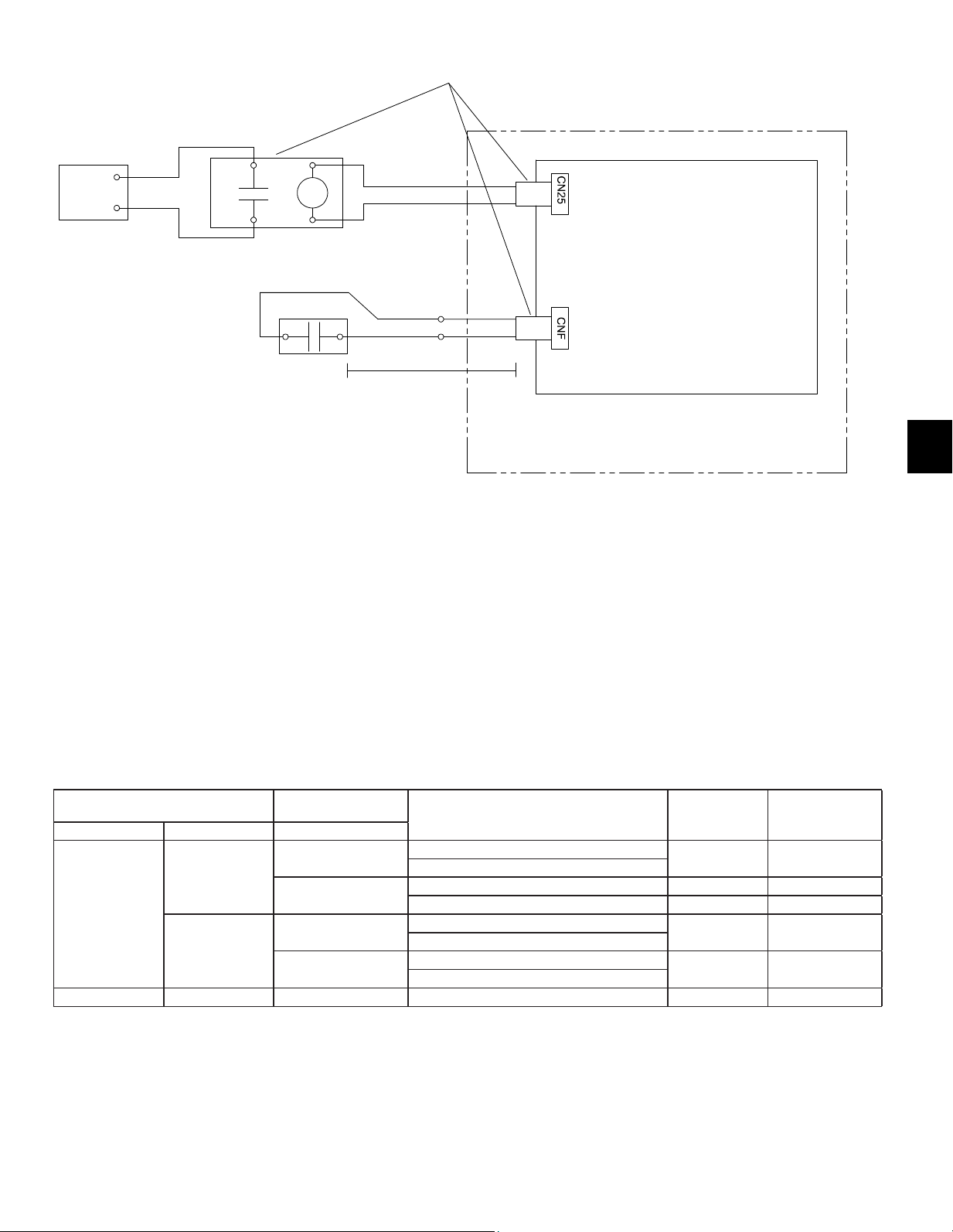
53
FR
13.6.Humidi�cateur
Contrôledel’humidi�cateur
Séquencedefonctionnement:
1.Lerégulateurd’humiditéfermeCNF.
2.Leventilateurdémarreàunevitesseélevée.
3.CN25fournit12VCCpouractiverl’humidi�cateur
(nedépassezpas1wattparrelais).
4.Lorsquelerégulateurd’humidités’ouvre,leventilateurcontinuedefonctionnerpendant
30secondespouréliminertoutairhumidedesconduits.
5.Siledégivragedémarrependantlefonctionnementdel’humidi�cateur
CN25coupel’alimentation.
Régulateurd’humidité:
EntréeducontactAsanstension
Tensionnominaleducontact>=15VCC
Courantnominalducontact>=0,1A
Chargeminimaleapplicable=<1mAenCC
N° de mode
Sortie du régulateur
d’humidité
Condition
(pas de dégivrage/pas d’erreur)
Sortie CN25
Vitesse de
ventilation
13 16 Entrée CNF
2
1*
OFF
OpérationdechauffageetThermoinactif
OFF Réglage RC
OpérationdechauffageetThermoactif
ON
OpérationdechauffageetThermoinactif OFF Réglage RC
OpérationdechauffageetThermoactif ON Élevée
2
OFF
OpérationdechauffageetThermoinactif
OFF Réglage RC
OpérationdechauffageetThermoactif
ON
OpérationdechauffageetThermoinactif
ON Élevée
OpérationdechauffageetThermoactif
1 - -
Pasdecontrôledel’humidi�cateur
OFF Réglage RC
RC:Commandeàdistance
Leventilateurcontinuedefonctionnerpendant30secondesaprèsl’arrêtdel’humidi�cateur.
*Réglaged’usine
Régulateur
d’humidité
(sursite)
Humidi�cateur
Panneaudecontrôledansla
centraledetraitementd’air
Numérodepièce:CN24RELAY-KIT-CM3
Centrale de traitement d’air
max 30 ft.
Bobine
12 VCC
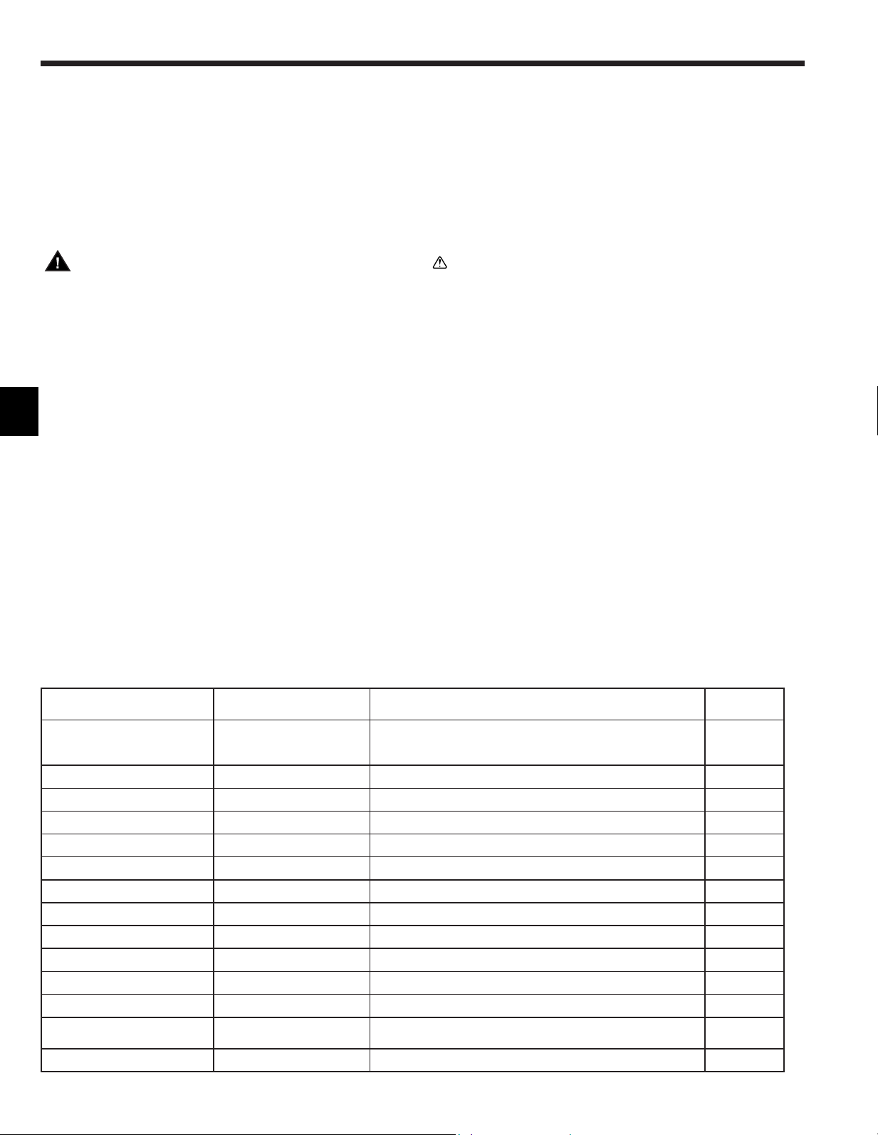
54
FR
14. Essai de fonctionnement
14.1. Avant l’essai de fonctionnement
Lorsque l’installation, le câblage et les tuyauteries des appareils
intérieursetextérieurssontterminés,véri�ezl’absencede
fuitederéfrigérant,la�xationdescâblesd’alimentationet
de commande, l’absence d’erreur de polarité et contrôlez
qu’aucune phase de l’alimentation n’est déconnectée.
Utilisez un mégohmmètre de 500 V pour s’assurer que la
résistance entre les bornes d’alimentation électrique et la terre
soitaumoinsde1,0MΩ.
N’effectuez pas ce test sur les bornes des câbles de commande
(circuit à basse tension).
Avertissement :
N’utilisez pas le climatiseur si la résistance de l’isolation
estinférieureà1,0MΩ.
Aprèsl’installationouaprèslamisehorstensiondel’appareil
pendantunepériodeprolongée,larésistancedel’isolationchuteen
dessousde1MΩenraisondel’accumulationderéfrigérantdansle
compresseur.Ilnes’agitpasd’undysfonctionnement.Effectuezles
procéduressuivantes.
1.Retirezlescâblesducompresseuretmesurezlarésistancede
l’isolationducompresseur.
2.Silarésistancedel’isolationestinférieureà1MΩ,le
compresseurestdéfectueuxoularésistanceachutéenraisonde
l’accumulationderéfrigérantdanslecompresseur.
3.Aprèsavoirconnectélescâblesaucompresseur,celui-ci
commenceàchaufferdèsqu’ilestsoustension.Aprèsavoirmis
soustensionlecompresseurpendantlesduréesindiquéesci-
dessous,mesurezdenouveaularésistancedel’isolation.
•Larésistancedel’isolationchuteenraisondel’accumulationde
réfrigérantdanslecompresseur.Larésistanceaugmenteau-dessus
de1MΩaprèsquelecompresseuraitchauffépendantdeuxàtrois
heures.
(Letempsmisparlecompresseurpourchauffervarieselonles
conditionsatmosphériquesetl’accumulationderéfrigérant.)
•Pourfairefonctionnerlecompresseurdanslequels’estaccumulé
duréfrigérant,ilestnécessairedelefairechaufferpendantaumoins
12heuresa�nd’évitertoutedéfaillance.
4.Silarésistancedel’isolationestsupérieureà1MΩ,le
compresseurn’estpasdéfectueux.
Précaution :
• Le compresseur fonctionnera uniquement si les
connexions des phases de l’alimentation électrique
sont correctes.
• Mettez l’appareil sous tension au moins 12 heures avant
de le faire fonctionner.
− Lamiseenmarchedel’appareilimmédiatementaprèssa
misesoustensionpourraitprovoquerdesérieuxdégâts
auxélémentsinternes.Nemettezpasl’appareilhors
tensionpendantlasaisondefonctionnement.
14.3. Autocontrôle
Pour en savoir plus, reportez-vous au manuel d’installation fourni avec chaque commande à distance.
Thermostat RF non établi.
[TypedemessageA]Erreursdétectéesparl’appareilintérieur
Télécommandesans�linfrarouge
Commande à distance câblée
Thermostat RF
Symptôme Remarque
Bips/Clignotement du
témoin OPERATION INDICATOR
(Nombre de fois)
Code de contrôle
1 P1 Erreurdecapteurd’entréed’air
2 P2,P9 Erreurdecapteurdetuyau(tuyaudeliquideouà2phases)
3 E6,E7 Erreurdecommunicationentrelesappareilsintérieuretextérieur
4 P4 Erreurdecapteurd’évacuation
5 P5 Erreurdepompedevidange
6 P6 Protectioncontrelegel/lessurchauffes
7 EE Erreurdecommunicationentrelesappareilsintérieuretextérieur
8 P8 Erreurdetempératuredestuyaux
9 E4 Erreurderéceptiondessignauxdelacommandeàdistance
10 – –
11 Pb Erreurdemoteurduventilateur
12 Fb Erreurdusystèmedecommandedel’appareilintérieur(erreur
demémoire,etc.)
Aucunson – – Aucunecorrespondance
14.2. Essai de fonctionnement
Pour en savoir plus, reportez-vous au manuel d’installation fourni avec chaque commande à distance.
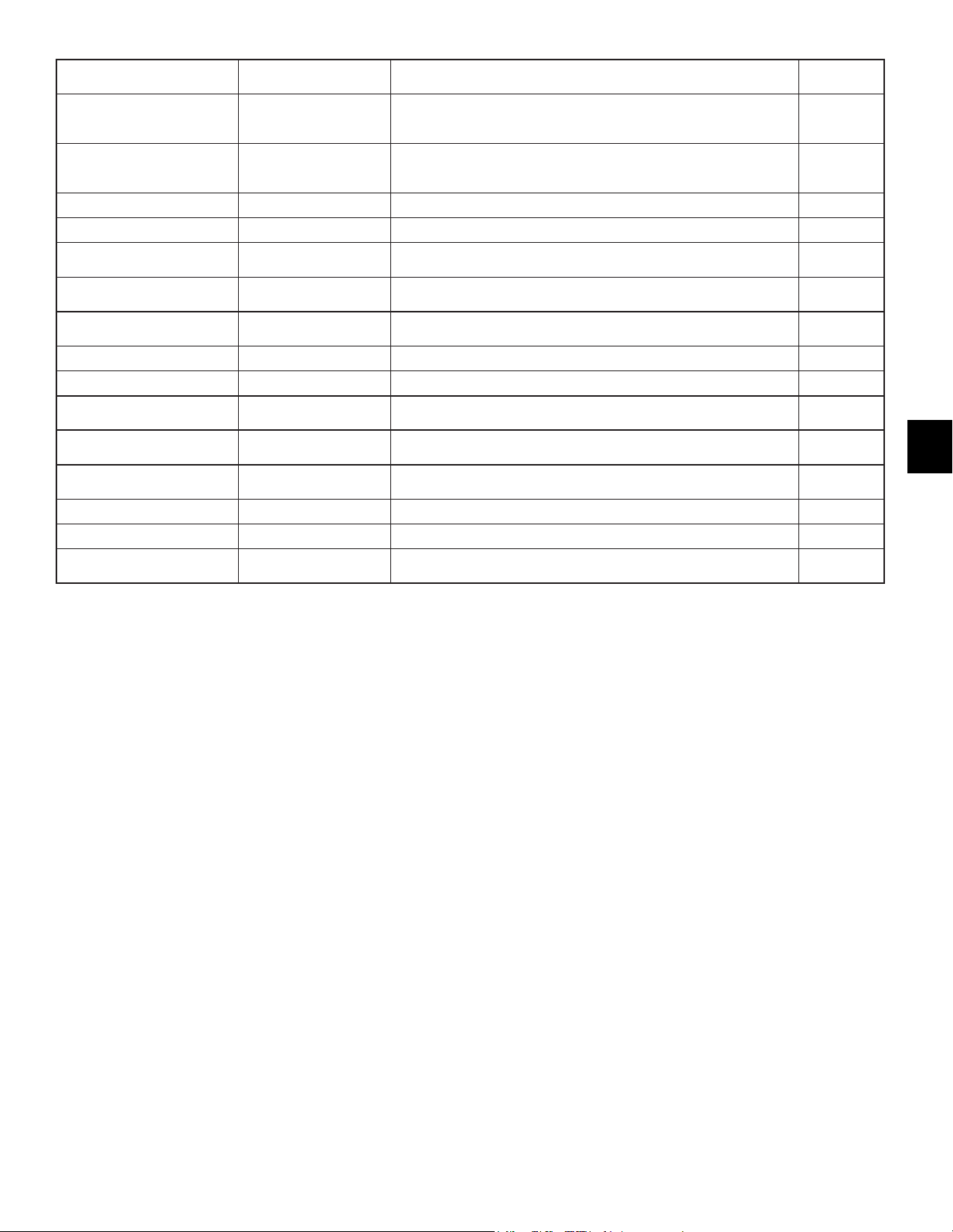
55
FR
[TypedemessageB]Erreursdétectéesparunappareilautrequel’appareilintérieur(appareilextérieur,etc.)
Télécommandesans�linfrarouge
Commande à distance câblée
Thermostat RF
Symptôme Remarque
Bips/Clignotement du
témoin OPERATION INDICATOR
(Nombre de fois)
Code de contrôle
1 E9 Erreurdecommunicationentrelesappareilsintérieuretextérieur(Erreur
detransmission)
(Appareilextérieur)
2 UP Interruptiondessurintensitésducompresseur
3 U3,U4 Ouverture/Court-circuitdesthermistancesdel’appareilextérieur
4 UF Interrupteurdessurintensitésducompresseur(Lorsquelecompresseur
estverrouillé)
5 U2 Températuredelasortied’airanormalementélevée/49Cenfonctionne-
ment/réfrigérantinsuf�sant
6 U1,Ud Pressionanormalementélevée(63Henfonctionnement)/Protection
contrelessurchauffes
7 U5 Températuredudissipateurdechaleuranormale
8 U8 Arrêtdelaprotectionduventilateurdel’appareilextérieur
9 U6 Interruptiondessurintensitésducompresseur/Anomaliedumodule
d’alimentation
10 U7 Anomalieduchauffagesuperchaudenraisond’unefaibletempérature
de sortie d’air
11 U9,UH Anomalietellequ’unesurintensitéouunebaissedetensionetsignal
synchroneanormalsurlecircuitprincipal/Erreurdecapteurdecourant
12 – –
13 – –
14 Autres Autreserreurs(Reportez-vousaumanueltechniquedel’appareilexté-
rieur.)
*1Silebipneretentitpasdenouveauaprèslaréceptiondesdeuxbipsinitiauxcon�rmantlesignaldedémarragedel’autocontrôle
et si le témoin OPERATION INDICATOR ne s’allume pas, les erreurs ne seront pas enregistrées.
*2Silebipretentittroisfoisdesuite“bip,bip,bip(0,4+0,4+0,4s)”aprèslaréceptiondesdeuxbipsinitiauxcon�rmantlesignal
dedémarragedel’autocontrôle,l’adressederéfrigérantspéci�éen’estpascorrecte.
•Surlatélécommandesans�linfrarouge
Lasonneriecontinuedelasectionderéceptiondel’appareilintérieurretentit.
Clignotementdutémoindefonctionnement
•Surlacommandeàdistancecâblée
Codedevéri�cationaf�chésurl’af�cheurLCD.
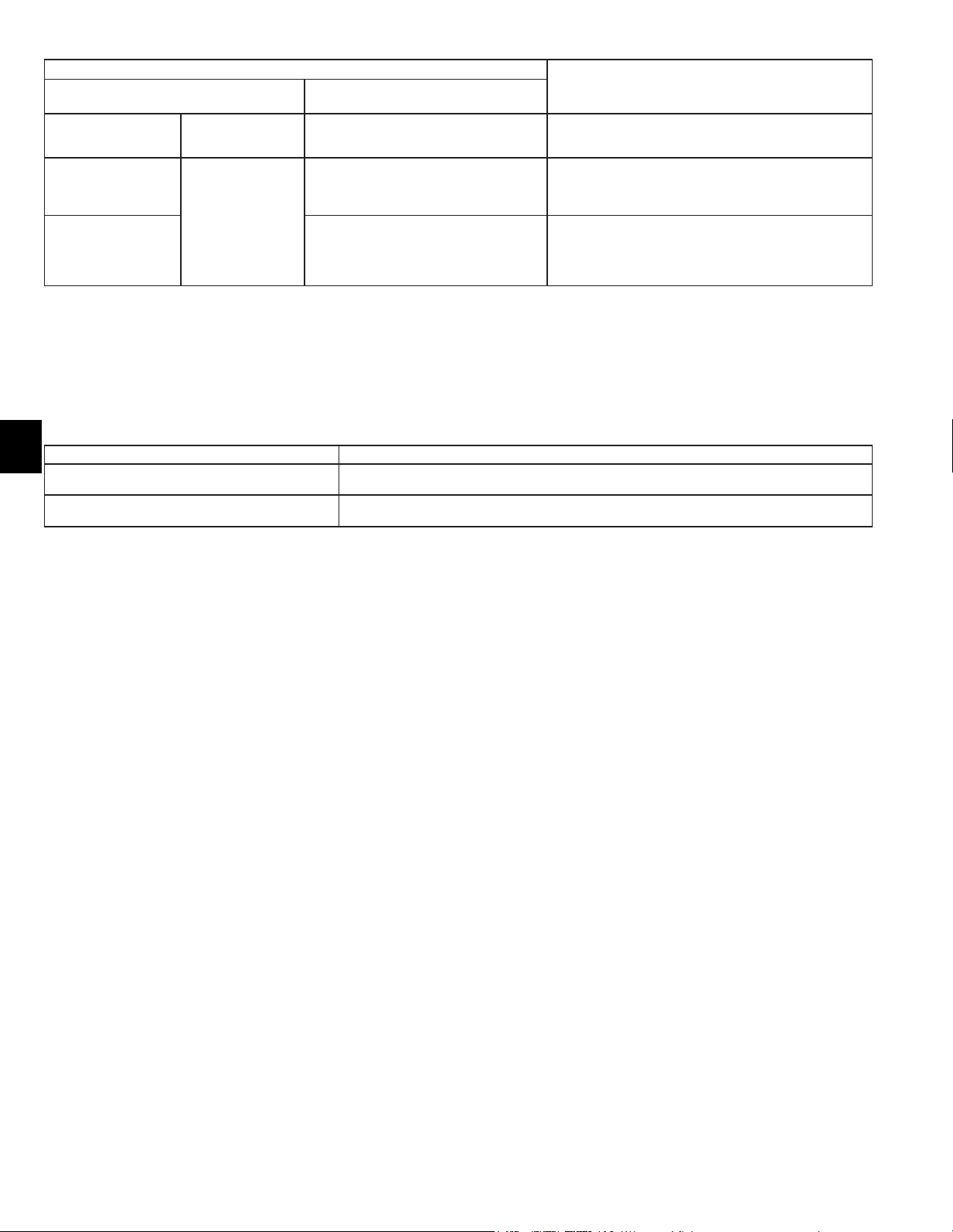
56
FR
14.4. FONCTION DE REDÉMARRAGE AUTOMATIQUE
Panneau de contrôle intérieur
CemodèleestéquipédelaFONCTIONDEREDÉMARRAGEAUTOMATIQUE.
Lorsquel’appareilintérieurestcontrôléàl’aidedelacommandeàdistance,lemodedefonctionnement,
latempératurerégléeetlavitesseduventilateursontmémorisésparlepanneaudecontrôleintérieur.
Lafonctionderedémarrageautomatiqueremetl’appareilenserviceaumomentoùlatensionsecteurestrétablie
aprèsunecoupuredecourant.
RéglezlaFONCTIONDEREDÉMARRAGEAUTOMATIQUEàl’aidedelacommandeàdistance.(Moden°01)
•Sil’appareilnefonctionnepascorrectementaprèsl’essaidefonctionnementci-dessus,reportez-vousautableausuivantpourrésoudreleproblème.
Symptôme
Cause
Commande à distance câblée
LED 1, 2 (carte du circuit imprimé de
l’appareil extérieur)
PLEASEWAIT
(VEUILLEZPATIENTER)
Pendant2minutesenviron
aprèslamisesoustension
Aprèsl’éclairagedelaLED1,2,laLED2s’éteint,
etseulelaLED1resteéclairée.(Fonctionnement
correct)
•Pendant2minutesenvironaprèslamisesoustension,lacommande
àdistancenepeutpasêtreutiliséeenraisondudémarragedusystème.
(Fonctionnementcorrect)
PLEASEWAIT
(VEUILLEZPATIENTER)→
Coded’erreur
Àla�nde2minutesenviron
aprèslamisesoustension
SeulelaLED1estéclairée.→LaLED1,2clignote.
•Leconnecteurdudispositifdeprotectiondel’appareilextérieurn’estpas
raccordé.
•Câblageinverséouavecphaseouvertedubornierd’alimentationde
l’appareilextérieur(L1,L2,L3)
Les messages n’apparaissent
pasmêmelorsquel’interrup-
teurdefonctionnementest
activé(letémoindefonction-
nementnes’allumepas).
SeulelaLED1estéclairée.→LaLED1,2clignote
deuxfois,laLED2clignoteunefois.
•Câblageincorrectentrelesappareilsintérieuretextérieur
(polaritéincorrectedeS1,S2,S3)
•Court-circuitsurlecâbledelacommandeàdistance
Danslesconditionsrépertoriéesci-avant,lephénomènesuivantseproduitauniveaudelatélécommandesans�linfrarouge.
•Aucunsignaln’estacceptéparlatélécommande.
•LetémoinOPEclignote.
•Lasonnerieémetuncourtbruitmétallique.
Remarque :
Le fonctionnement n’est pas possible durant les 30 secondes suivant l’annulation de la sélection d’une fonction. (Fonctionnement correct)
PourladescriptiondechaqueLED(LED1,2,3)surlacommandeintérieure,reportez-vousautableausuivant.
LED1(alimentationdumicroprocesseur) Indiquesil’alimentationdelacommandeestfournie.Assurez-vousquecetteLEDesttoujourséclairée.
LED2(alimentationdelacommandeàdistance)
Indiquesil’alimentationestfournieàlacommandeàdistance.CetteLEDs’éclaireseulementdanslecasde
l’appareilintérieurraccordéàl’adressederéfrigérantdel’appareilextérieur“0”.
LED3(communicationentrelesappareilsintérieuret
extérieur)
Indiquel’étatdecommunicationentrelesappareilsintérieuretextérieur.Assurez-vousquecetteLED
clignotetoujours.

57
FR
Please be sure to put the contact address/telephone number on
this manual before handing it to the customer.
This product is designed and intended for use in the residential,
commercial and light-industrial environment.
www.mitsubishielectric-usa.com
Toll Free: 800-433-4822
MITSUBISHI ELECTRIC US, INC.
MEUS DOC# MD-1404-K024 Ver. 3
PA79D213H09 January 2022
Speci�cationsaresubjecttochangewithoutnotice. © 2022 Mitsubishi Electric US, Inc.