Loading ...
Loading ...
Loading ...
15
EE
EN
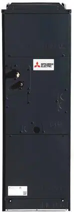
Step. 4b Cut the plastic ties that are securing the extra wiring
for the Thermistor (CN44). Route the thermistor wires into the
Electrical section of the air handler on the left side of the coil.
-Use the metal tab in Detail A to secure the wires
-The notch in the drain pan allows the wires to pass the drain pan,
go through the sheetmetal shelf which now supports the Coil
Assembly and enter the Electrical section of the Air Handler.
Reconnect the Thermistor (CN44) to the control board.
Step. 4c In order to prevent water from running down the
Thermistor wires into the electrical area, a Drip Loop MUST be
installed to direct water into the drain pan.
3rd
1st
2nd
METAL TAB
BEND AROUND
THE WIRE
HARNESS
DRIP LOOP
TO ELECTRICAL
SECTION
DETAIL A
INSIDE DRAIN PAN
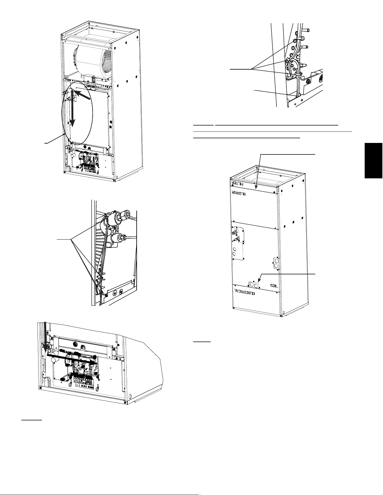
Step. 5 Reinstall the panels over the drains and refrigerant lines.
Next, install the panels which cover the Coil (1
st
), Electrical (2
nd
),
Blower (3
rd
) and Filter (4
th
). NOTE: The panel which covers the Coil
Assembly will be installed upright as the original vertical orientation
from the factory, while the other panels’ text will read upside down.
PRIMARY
DRAIN
3/4
”
FPT
4th
DÉTAIL A
Loading ...
Loading ...
Loading ...