Loading ...
Loading ...
Loading ...
18
For the Installer
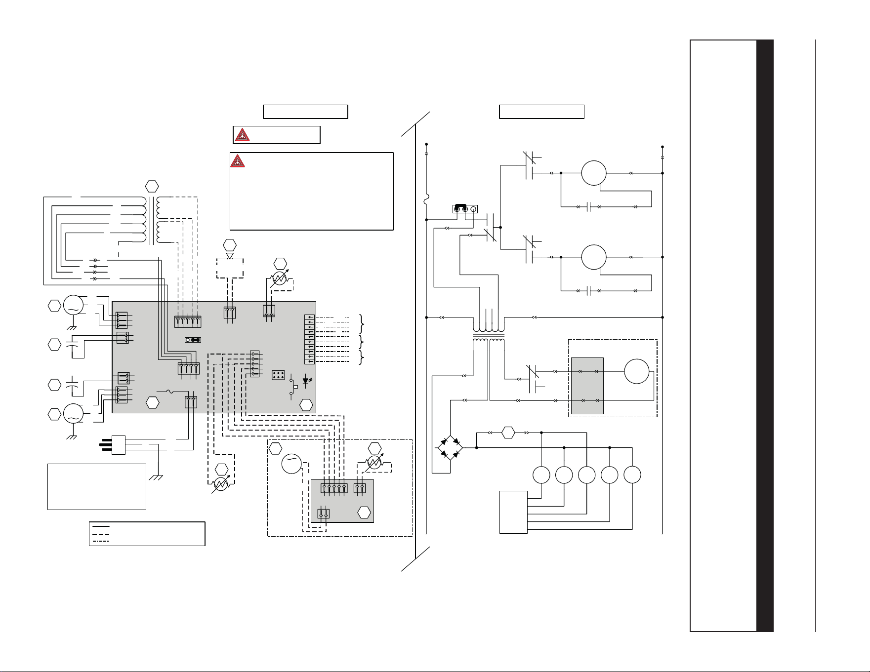
9. WIRING DIAGRAMS
For the following units:
S10 ERVPLUS S10 ERV 70E+ 70E ERV
⚠ WARNING
• Risk of electric shocks. Before performing any maintenance or servicing, always disconnect the unit from its
power source.
• This product is equipped with an overload protection (fuse). A blown fuse indicates an overload or a short-circuit
situation. If the fuse blows, unplug the product from the outlet. Discontinue using the unit and contact technical
support.
L
INE
N
EUTRAL
120 VAC
J10-2
J10-1
EXHAUST FAN
MOTOR M1
M
C1
M
OTOR
C
APACITOR
K1
J5-1 J5-2
J7-1 J7-2 J5-3
SUPPLY FAN
MOTOR M2
M
C2
M
OTOR
C
APACITOR
K3
J4-1 J4-2
J6-1 J6-2 J4-3
J9-4
OPTIONAL DAMPER SYSTEM
DAMPER MOTOR
M3
M
J2-1 J3-1
J2-2 J3-2
J12-1
J12-2
K4
J8-2
J8-1
J8-5
J8-4
J11-1
J11-2
S1
K4K1 K2 K3 K5
+
-
~
~
T1
9.5 VAC 24 VAC
103 VAC
76 VAC
64 VAC
55 VAC
NC NC
J9-1
J9-3
J9-2
F1
321
JU1
M
H
WIRING DIAGRAM
LINE VOLTAGE FACTORY WIRING
CLASS 2 LOW VOLTA GE FACTORY WIRING
CLASS 2 LOW VOLTA GE FIELD WIRING
OVERRIDE SWITCH
(OPTIONAL)
F
IELD WIRING
REMOTE CONTROL
FURNACE BLOWER
INTERLOCK (OPTIONAL)
B
G
R
R
G
BK
Y
Y
OL
OC
I
J14
10
9
8
7
6
5
4
3
2
1
J20
12
J13
ICP
A1
ELECTRONIC
ASSEMBLY
12345
J12
J11
12
4321
J9
J10
21
F1
3A
3AG TYPE
321
JU1
MH
43215
J8
J5
J7
1
1
2
2
3
J6
1
2
J4
1
2
3
215 4321
12
J3
J2 J1
M3
A2
THERMISTOR
DAMPER ELECTRONIC
ASSEMBLY
DAMPER MOTOR
R1
BK
BK
BK
W
G
120 VAC
60 Hz
C2
M2
BL
BN
BK
M1
C1
BL
BN
BK
SUPPLY FAN
MOTOR
E
XHAUST FAN
MOTOR
MOTOR
CAPACITOR
MOTOR
CAPACITOR
T1
24 V Class 2
9.5 V
Class 2
120 V
103 V
76 V
64 V
55 V
neutral
BK
BL
BN
GY
R
W
R
R
GY
BN
BL BL
NC
NC
Y
Y
O
O
W
S1
R2
DOOR INTERLOCK SWITCH
(OPTIONAL, MAGNETICALLY
ACTUATED REED SWITCH)
T
HERMISTOR
W
OPTIONAL DAMPER SYSTEM
Critical characteristic.
NOTES
1.
Protected against fire with
UL listed/CSA Certified line fuse.
2. If any of the original wire, as supplied, must
be replaced, use the same equivalent wire.
3. Field wiring must comply with applicable
codes, ordinances and regulations.
4. Remote controls (class 2 circuit) available,
see instruction manual.
5. Furnace fan circuit must be class 2 circuit only.
K2
CPU
LOGIC DIAGRAM
VE0437A
COLOR CODE
BLACK
BLUE
BROWN
GREEN
GREY
BK
BL
BN
G
GY
ORANGE
RED
WHITE
YELLOW
O
R
W
Y
NC NO CONNECTION
R1
THERMISTOR
(OPTIONAL)
OR
ref: 24600_REV-A
Loading ...
Loading ...
Loading ...