
DS-K3B631TX Series Swing Barrier
User Manual
Legal Informaon
About this Document
●
This Document includes instrucons for using and managing the Product. Pictures, charts,
images and all other
informaon hereinaer are for descripon and explanaon only.
●
The
informaon contained in the Document is subject to change, without noce, due to
rmware updates or other reasons. Please nd the latest version of the Document at the
Hikvision website ( hps://www.hikvision.com ). Unless otherwise agreed, Hangzhou Hikvision
Digital Technology Co., Ltd. or its aliates (hereinaer referred to as "Hikvision") makes no
warranes, express or implied.
●
Please use the Document with the guidance and assistance of professionals trained in
supporng the Product.
About this Product
●
This product can only enjoy the aer-sales service support in the country or region where the
purchase is made.
●
If the product you choose is a video product, please scan the following QR code to obtain the
"Iniaves on the Use of Video Products", and read it carefully.
Acknowledgment of Intellectual Property Rights
●
Hikvision owns the copyrights and/or patents related to the technology embodied in the
Products described in this Document, which may include licenses obtained from third pares.
●
Any part of the Document, including text, pictures, graphics, etc., belongs to Hikvision. No part
of this Document may be excerpted, copied, translated, or modied in whole or in part by any
means without
wrien permission.
●
and other Hikvision's trademarks and logos are the properes of Hikvision in
various
jurisdicons.
●
Other trademarks and logos menoned are the properes of their respecve owners.
LEGAL DISCLAIMER
●
TO THE MAXIMUM EXTENT PERMITTED BY APPLICABLE LAW, THIS DOCUMENT AND THE
PRODUCT DESCRIBED, WITH ITS HARDWARE, SOFTWARE AND FIRMWARE, ARE PROVIDED "AS
IS" AND "WITH ALL FAULTS AND ERRORS". HIKVISION MAKES NO WARRANTIES, EXPRESS OR
DS-K3B631TX Series Swing Barrier User Manual
i

IMPLIED, INCLUDING WITHOUT LIMITATION, MERCHANTABILITY, SATISFACTORY QUALITY, OR
FITNESS FOR A PARTICULAR PURPOSE. THE USE OF THE PRODUCT BY YOU IS AT YOUR OWN RISK.
IN NO EVENT WILL HIKVISION BE LIABLE TO YOU FOR ANY SPECIAL, CONSEQUENTIAL,
INCIDENTAL, OR INDIRECT DAMAGES, INCLUDING, AMONG OTHERS, DAMAGES FOR LOSS OF
BUSINESS PROFITS, BUSINESS INTERRUPTION, OR LOSS OF DATA, CORRUPTION OF SYSTEMS, OR
LOSS OF DOCUMENTATION, WHETHER BASED ON BREACH OF CONTRACT, TORT (INCLUDING
NEGLIGENCE), PRODUCT LIABILITY, OR OTHERWISE, IN CONNECTION WITH THE USE OF THE
PRODUCT, EVEN IF HIKVISION HAS BEEN ADVISED OF THE POSSIBILITY OF SUCH DAMAGES OR
LOSS.
●
YOU ACKNOWLEDGE THAT THE NATURE OF THE INTERNET PROVIDES FOR INHERENT SECURITY
RISKS, AND HIKVISION SHALL NOT TAKE ANY RESPONSIBILITIES FOR ABNORMAL OPERATION,
PRIVACY LEAKAGE OR OTHER DAMAGES RESULTING FROM CYBER-ATTACK, HACKER ATTACK,
VIRUS INFECTION, OR OTHER INTERNET SECURITY RISKS; HOWEVER, HIKVISION WILL PROVIDE
TIMELY TECHNICAL SUPPORT IF REQUIRED.
●
YOU AGREE TO USE THIS PRODUCT IN COMPLIANCE WITH ALL APPLICABLE LAWS, AND YOU ARE
SOLELY RESPONSIBLE FOR ENSURING THAT YOUR USE CONFORMS TO THE APPLICABLE LAW.
ESPECIALLY, YOU ARE RESPONSIBLE, FOR USING THIS PRODUCT IN A MANNER THAT DOES NOT
INFRINGE ON THE RIGHTS OF THIRD PARTIES, INCLUDING WITHOUT LIMITATION, RIGHTS OF
PUBLICITY, INTELLECTUAL PROPERTY RIGHTS, OR DATA PROTECTION AND OTHER PRIVACY
RIGHTS. YOU SHALL NOT USE THIS PRODUCT FOR ANY PROHIBITED END-USES, INCLUDING THE
DEVELOPMENT OR PRODUCTION OF WEAPONS OF MASS DESTRUCTION, THE DEVELOPMENT OR
PRODUCTION OF CHEMICAL OR BIOLOGICAL WEAPONS, ANY ACTIVITIES IN THE CONTEXT
RELATED TO ANY NUCLEAR EXPLOSIVE OR UNSAFE NUCLEAR FUEL-CYCLE, OR IN SUPPORT OF
HUMAN RIGHTS ABUSES.
●
IN THE EVENT OF ANY CONFLICTS BETWEEN THIS DOCUMENT AND THE APPLICABLE LAW, THE
LATTER PREVAILS.
Data
Protecon
●
To protect data, the development of Hikvision Products incorporates privacy by design
principles. For example, for Products with facial
recognion features, biometrics data is stored in
your Products with encrypon method; for ngerprint Products, only ngerprint template will be
saved, which is impossible to reconstruct a
ngerprint image.
●
As a data controller/processor, you may process personal data, including collecon, storage, use,
processing, disclosure,
deleon, etc. You are advised to pay aenon to and comply with
applicable laws and regulaons related to the protecon of personal data, including without
limitaon, conducng security controls to safeguard personal data, such as, implemenng
reasonable administrave and physical security controls, conduct periodic reviews and the
assessments of the
eecveness of your security controls.
© Hangzhou Hikvision Digital Technology Co., Ltd. All rights reserved.
DS-K3B631TX Series Swing Barrier User Manual
ii
Regulatory Informaon
FCC Informaon
Please take aenon that changes or modicaon not expressly approved by the party responsible
for compliance could void the user’s authority to operate the equipment.
FCC compliance: This equipment has been tested and found to comply with the limits for a Class A
digital device, pursuant to part 15 of the FCC Rules. These limits are designed to provide
reasonable
protecon against harmful interference when the equipment is operated in a
commercial environment. This equipment generates, uses, and can radiate radio frequency energy
and, if not installed and used in accordance with the
instrucon manual, may cause harmful
interference to radio communicaons. Operaon of this equipment in a residenal area is likely to
cause harmful interference in which case the user will be required to correct the interference at his
own expense.
FCC
Condions
This device complies with part 15 of the FCC Rules. Operaon is subject to the following two
condions:
1. This device may not cause harmful interference.
2. This device must accept any interference received, including interference that may cause
undesired operaon.
EU Conformity Statement
This product and - if applicable - the supplied accessories too are marked with "CE"
and comply therefore with the applicable harmonized European standards listed
under the EMC Direcve 2014/30/EU, RE Direcve 2014/53/EU,the RoHS Direcve
2011/65/EU
2012/19/EU (WEEE direcve): Products marked with this symbol cannot be disposed
of as unsorted municipal waste in the European Union. For proper recycling, return
this product to your local supplier upon the purchase of equivalent new equipment,
or dispose of it at designated
collecon points. For more informaon see:
www.recyclethis.info
2006/66/EC (baery direcve): This product contains a baery that cannot be
disposed of as unsorted municipal waste in the European Union. See the product
documentaon for specic baery informaon. The baery is marked with this
symbol, which may include
leering to indicate cadmium (Cd), lead (Pb), or mercury
(Hg). For proper recycling, return the
baery to your supplier or to a designated
collecon point. For more informaon see:www.recyclethis.info
DS-K3B631TX Series Swing Barrier User Manual
iii

This device complies with Industry Canada licence-exempt RSS standard(s). Operaon is subject to
the following two condions:
(1) this device may not cause interference, and
(2) this device must accept any interference, including interference that may cause undesired
operaon of the device.
Le présent appareil est conforme aux CNR d'Industrie Canada applicables aux appareils
radioexempts de licence.
L'exploitaon est autorisée aux deux condions suivantes :
(1) l'appareil ne doit pas produire de brouillage, et
(2)
l'ulisateur de l'appareil doit accepter tout brouillage radioélectrique subi, même si le
brouillage est suscepble d'en compromere le fonconnement.
COMPLIANCE NOTICE
The thermal series products might be subject to export controls in various countries or regions,
including without limitaon, the United States, European Union, United Kingdom and/or other
member countries of the Wassenaar Arrangement. Please consult your professional legal or
compliance expert or local government authories for any necessary export license requirements if
you intend to transfer, export, re-export the thermal series products between
dierent countries.
DS-K3B631TX Series Swing Barrier User Manual
iv

Safety Instrucon
These instrucons are intended to ensure that user can use the product correctly to avoid danger
or property loss.
The
precauon measure is divided into Dangers and Cauons:
Dangers: Neglecng any of the warnings may cause serious injury or death.
Cauons: Neglecng any of the cauons may cause injury or equipment damage.
Dangers: Follow these safeguards to prevent
serious injury or death.
Cauons: Follow these precauons to prevent
potenal injury or material damage.
Danger:
●
In the use of the product, you must be in strict compliance with the electrical safety regulaons
of the naon and region.
●
The equipment must be connected to an earthed mains socket-outlet.
●
Shock hazard! Disconnect all power sources before maintenance.
●
Do not touch the bare metal contacts of the inlets
aer the circuit breaker is turned o.
Electricity sll exists.
●
indicates hazardous live and the external wiring connected to the terminals requires
installaon by an instructed person.
●
Keep body parts away from fan blades. Disconnect the power source during servicing.
●
Keep body parts away from motors. Disconnect the power source during servicing.
●
To prevent possible hearing damage, do not listen at high volume levels for long periods.
●
All the electronic
operaon should be strictly compliance with the electrical safety regulaons,
re
prevenon regulaons and other related regulaons in your local region.
●
Do not connect several devices to one power adapter as adapter overload may cause over-heat
or
re hazard.
●
Please make sure that the power has been disconnected before you wire, install or dismantle the
device.
If the top caps should be open and the device should be powered on for maintenance, make
sure:
1. Power
o the fan to prevent the operator from geng injured accidentally.
2. Do not touch bare high-voltage components.
3. Make sure the switch’s wiring sequence is correct
aer maintenance.
●
Please make sure that the power has been disconnected before you wire, install or dismantle the
device.
●
When the product is installed on wall or ceiling, the device shall be
rmly xed.
●
If smoke, odors or noise rise from the device, turn
o the power at once and unplug the power
cable, and then please contact the service center.
DS-K3B631TX Series Swing Barrier User Manual
v

●
Do not ingest baery, Chemical Burn Hazard.
This product contains a coin/buon cell baery. If the coin/buon cell baery is swallowed, it
can cause severe internal burns in just 2 hours and can lead to death.
Keep new and used
baeries away from children. If the baery compartment does not close
securely, stop using the product and keep it away from children. If you think
baeries might have
been swallowed or placed inside any part of the body, seek immediate medical
aenon.
●
If the product does not work properly, please contact your dealer or the nearest service center.
Never aempt to disassemble the device yourself. (We shall not assume any responsibility for
problems caused by unauthorized repair or maintenance.)
Cauons:
●
The equipment shall not be exposed to dripping or splashing and that no objects lled with
liquids, such as vases, shall be placed on the equipment.
●
Ensure correct wiring of the terminals for connecon to an AC mains supply.
●
The equipment has been designed, when required,
modied for connecon to an IT power
distribuon system.
●
+ idenes the posive terminal(s) of equipment which is used with, or generates direct current.
+ idenes the negave terminal(s) of equipment which is used with, or generates direct
current.
●
No naked
ame sources, such as lighted candles, should be placed on the equipment.
●
This equipment is suitable for mounng on concrete or other non-combusble surface only.
●
Install the equipment according to the instrucons in this manual.
●
To prevent injury, this equipment must be securely
aached to the oor/wall in accordance with
the installaon instrucons.
●
Stainless steel may be corroded in some circumstances. You need to clean and care the device by
using the stainless steel cleaner. It is suggested to clean the device every month.
●
Do not drop the device or subject it to physical shock, and do not expose it to high
electromagnesm radiaon. Avoid the equipment installaon on vibraons surface or places
subject to shock (ignorance can cause equipment damage).
●
Do not place the device in extremely hot (refer to the
specicaon of the device for the detailed
operang temperature), cold, dusty or damp locaons, and do not expose it to high
electromagnec radiaon.
●
The device cover for indoor use shall be kept from rain and moisture.
●
Exposing the equipment to direct sun light, low
venlaon or heat source such as heater or
radiator is forbidden (ignorance can cause re danger).
●
Do not aim the device at the sun or extra bright places. A blooming or smear may occur
otherwise (which is not a
malfuncon however), and aecng the endurance of sensor at the
same
me.
●
Please use the provided glove when open up the device cover, avoid direct contact with the
device cover, because the acidic sweat of the ngers may erode the surface coang of the device
cover.
●
Please use a
so and dry cloth when clean inside and outside surfaces of the device cover, do
not use alkaline detergents.
DS-K3B631TX Series Swing Barrier User Manual
vi

●
Please keep all wrappers aer unpack them for future use. In case of any failure occurred, you
need to return the device to the factory with the original wrapper. Transportaon without the
original wrapper may result in damage on the device and lead to addional costs.
●
Improper use or replacement of the
baery may result in hazard of explosion. Replace with the
same or equivalent type only. Dispose of used
baeries according to the instrucons provided by
the
baery manufacturer.
●
Biometric
recognion products are not completely applicable to an-spoong environments. If
you require a higher security level, use mulple authencaon modes.
●
Do not stay in the lane when the device is reboong.
●
RISK OF EXPLOSION IF BATTERY IS REPLACED BY AN INCORRECT TYPE. DISPOSE OF USED
BATTERIES ACCORDING TO THE INSTRUCTIONS.
●
SUITABLE FOR MOUNTING ON CONCRETE OR OTHER NON-COMBUSTIBLE SURFACE ONLY.
●
The
instrucons shall require connecon of the equipment protecve earthing conductor to the
installaon protecve earthing conductor.
DS-K3B631TX Series Swing Barrier User Manual
vii

Available Models
Product Name Model Descripon
Swing Barrier DS-K3B631TX-L Le Pedestal
DS-K3B631TX-M Middle Pedestal
DS-K3B631TX-R Right Pedestal
DS-K3B631TX Series Swing Barrier User Manual
viii

Contents
Chapter 1 Overview .................................................................................................................... 1
1.1 Introducon ........................................................................................................................... 1
1.2 Main Features ........................................................................................................................ 1
Chapter 2 Light Introducon ....................................................................................................... 3
2.1 Light Descripon .................................................................................................................... 3
2.2 Side Light Board DIP Switch Descripon ................................................................................ 4
Chapter 3 System Wiring ............................................................................................................ 8
Chapter 4 Installaon ............................................................................................................... 12
Chapter 5 General Wiring ......................................................................................................... 14
5.1 Components
Introducon .................................................................................................... 14
5.2 Wiring .................................................................................................................................. 16
5.3 Terminal
Descripon ............................................................................................................ 18
5.3.1 Main Lane Control Board Terminal Descripon .......................................................... 18
5.3.2 Sub Lane Control Board Terminal Descripon ............................................................ 18
5.3.3 Main Access Control Board Terminal
Descripon ....................................................... 19
5.3.4 Sub Access Control Board Terminal Descripon ......................................................... 20
5.3.5 Main User Extended Interface Board .......................................................................... 22
5.3.6 Sub User Extended Interface Board ............................................................................ 25
5.3.7 User Core Board Terminal
Descripon ........................................................................ 27
5.3.8 Card Reader Board Terminal Descripon .................................................................... 27
5.3.9 Arrow Light Board Terminal
Descripon ..................................................................... 28
5.3.10 Upper IR Adapter Board Terminal Descripon .......................................................... 28
5.3.11 Lower IR Adapter Board Terminal Descripon .......................................................... 29
5.3.12 RS-485 Wiring ........................................................................................................... 29
5.3.13 RS-232 Wiring ........................................................................................................... 30
5.3.14 Wiegand Wiring ........................................................................................................ 30
DS-K3B631TX Series Swing Barrier User Manual
ix

5.3.15 Barrier Control Wiring ............................................................................................... 31
5.3.16 Alarm Output Wiring ................................................................................................. 31
5.3.17 Alarm Input Wiring ................................................................................................... 32
Chapter 6 Device
Sengs ......................................................................................................... 34
6.1 Set Study Mode .................................................................................................................... 34
6.2 Pair Keyfob (Oponal) .......................................................................................................... 35
6.3 Inialize Device .................................................................................................................... 36
Chapter 7 Acvaon ................................................................................................................. 39
7.1 Acvate via Device ............................................................................................................... 39
7.2 Acvate via Web Browser .................................................................................................... 41
7.3 Acvate via SADP ................................................................................................................. 41
7.4 Acvate Device via iVMS-4200 Client Soware ................................................................... 43
Chapter 8 Quick
Operaon ....................................................................................................... 44
8.1 Set Device Hotspot ............................................................................................................... 44
8.2
Acvate via Device ............................................................................................................... 45
8.3 Set Applicaon Mode .......................................................................................................... 47
8.4 Set Network Parameters ...................................................................................................... 49
8.5 Privacy
Sengs .................................................................................................................... 50
8.6 Keyfob Sengs .................................................................................................................... 51
8.7 Set Administrator ................................................................................................................. 53
Chapter 9 Quick
Operaon via Web Browser ............................................................................ 56
9.1 Time Sengs ........................................................................................................................ 56
9.2 Environment
Sengs ........................................................................................................... 56
9.3 Privacy Sengs .................................................................................................................... 57
9.4 Administrator Sengs ......................................................................................................... 57
Chapter 10
Operaon via Web Browser .................................................................................... 58
10.1 Login .................................................................................................................................. 58
10.2 Overview ............................................................................................................................ 58
DS-K3B631TX Series Swing Barrier User Manual
x

10.3 Person Management .......................................................................................................... 59
10.4 Search Event ...................................................................................................................... 60
10.5 Device Management .......................................................................................................... 60
10.6
Conguraon ..................................................................................................................... 60
10.6.1 Set Local Parameters ................................................................................................. 60
10.6.2 View Device Informaon ........................................................................................... 61
10.6.3 Set Time .................................................................................................................... 61
10.6.4 Set DST ...................................................................................................................... 62
10.6.5 Change Administrator's Password ............................................................................. 62
10.6.6 Online Users .............................................................................................................. 62
10.6.7 View Device Arming/Disarming Informaon ............................................................ 62
10.6.8 Network Sengs ....................................................................................................... 63
10.6.9 Set Video and Audio Parameters .............................................................................. 65
10.6.10 Set Image Parameters ............................................................................................. 65
10.6.11 Event Linkage .......................................................................................................... 66
10.6.12 Access Control Sengs ........................................................................................... 67
10.6.13
Turnsle .................................................................................................................. 71
10.6.14 Card Sengs ........................................................................................................... 76
10.6.15 Set Privacy Parameters ............................................................................................ 77
10.6.16 Set Biometric Parameters ....................................................................................... 78
10.6.17 Screen Display ......................................................................................................... 79
10.6.18
Noce Publicaon ................................................................................................... 80
10.6.19 Customize Audio Content ....................................................................................... 81
10.6.20 Upgrade and Maintenance ..................................................................................... 83
10.6.21 Device Debugging ................................................................................................... 84
10.6.22 Component Status .................................................................................................. 84
10.6.23 Log Query ................................................................................................................ 85
10.6.24 Advanced
Sengs ................................................................................................... 85
DS-K3B631TX Series Swing Barrier User Manual
xi

10.6.25 Cercate Management ......................................................................................... 86
Chapter 11 Congure the Device via the Mobile Browser ......................................................... 88
11.1 Login .................................................................................................................................. 88
11.2 Overview ............................................................................................................................ 88
11.3
Conguraon ..................................................................................................................... 89
11.3.1 Turnsle Basic Parameters ........................................................................................ 89
11.3.2 User Management .................................................................................................... 90
11.3.3 Keyfob Sengs .......................................................................................................... 92
11.3.4 Light Sengs ............................................................................................................. 93
11.3.5 Network Sengs ....................................................................................................... 97
11.3.6 Device Basic Sengs ............................................................................................... 100
11.3.7 Access Control Sengs ........................................................................................... 102
11.3.8 Face Parameters
Sengs ........................................................................................ 110
11.3.9 View Device
Informaon ......................................................................................... 114
11.3.10 Device Capacity ..................................................................................................... 114
11.3.11 Log Export ............................................................................................................. 114
11.3.12 Restore and Reboot .............................................................................................. 114
Chapter 12 Client
Soware Conguraon ............................................................................... 115
12.1 Conguraon Flow of Client Soware ............................................................................. 115
12.2 Device Management ........................................................................................................ 116
12.2.1 Add Device .............................................................................................................. 116
12.2.2 Reset Device Password ........................................................................................... 118
12.2.3 Manage Added Devices .......................................................................................... 119
12.3 Group Management ......................................................................................................... 120
12.3.1 Add Group ............................................................................................................... 120
12.3.2 Import Resources to Group ..................................................................................... 120
12.4 Person Management ........................................................................................................ 121
12.4.1 Add
Organizaon .................................................................................................... 121
DS-K3B631TX Series Swing Barrier User Manual
xii

12.4.2 Import and Export Person Idenfy Informaon ...................................................... 122
12.4.3 Get Person Informaon from Access Control Device .............................................. 124
12.4.4 Issue Cards to Persons in Batch ............................................................................... 125
12.4.5 Report Card Loss ..................................................................................................... 125
12.4.6 Set Card Issuing Parameters .................................................................................... 126
12.5
Congure Schedule and Template ................................................................................... 127
12.5.1 Add Holiday ............................................................................................................. 127
12.5.2 Add Template .......................................................................................................... 128
12.6 Set Access Group to Assign Access Authorizaon to Persons .......................................... 129
12.7 Congure Advanced Funcons ........................................................................................ 131
12.7.1 Congure Device Parameters .................................................................................. 132
12.7.2 Congure Other Parameters ................................................................................... 139
12.8 Door/Elevator Control ...................................................................................................... 141
12.8.1 Control Door Status ................................................................................................. 142
12.8.2 Check Real-Time Access Records ............................................................................ 143
Appendix A. Tips When Collecng/Comparing Face Picture .................................................... 145
Appendix B. DIP Switch ........................................................................................................... 146
B.1 DIP Switch
Descripon ....................................................................................................... 146
B.2 DIP Switch Corresponded Funcons .................................................................................. 146
B.3 Side Light Board DIP Switch
Descripon ............................................................................ 147
Appendix C. Event and Alarm Type ......................................................................................... 151
Appendix D. Error Code Descripon ........................................................................................ 152
Appendix E.
Communicaon Matrix and Device Command ..................................................... 154
DS-K3B631TX Series Swing Barrier User Manual
xiii
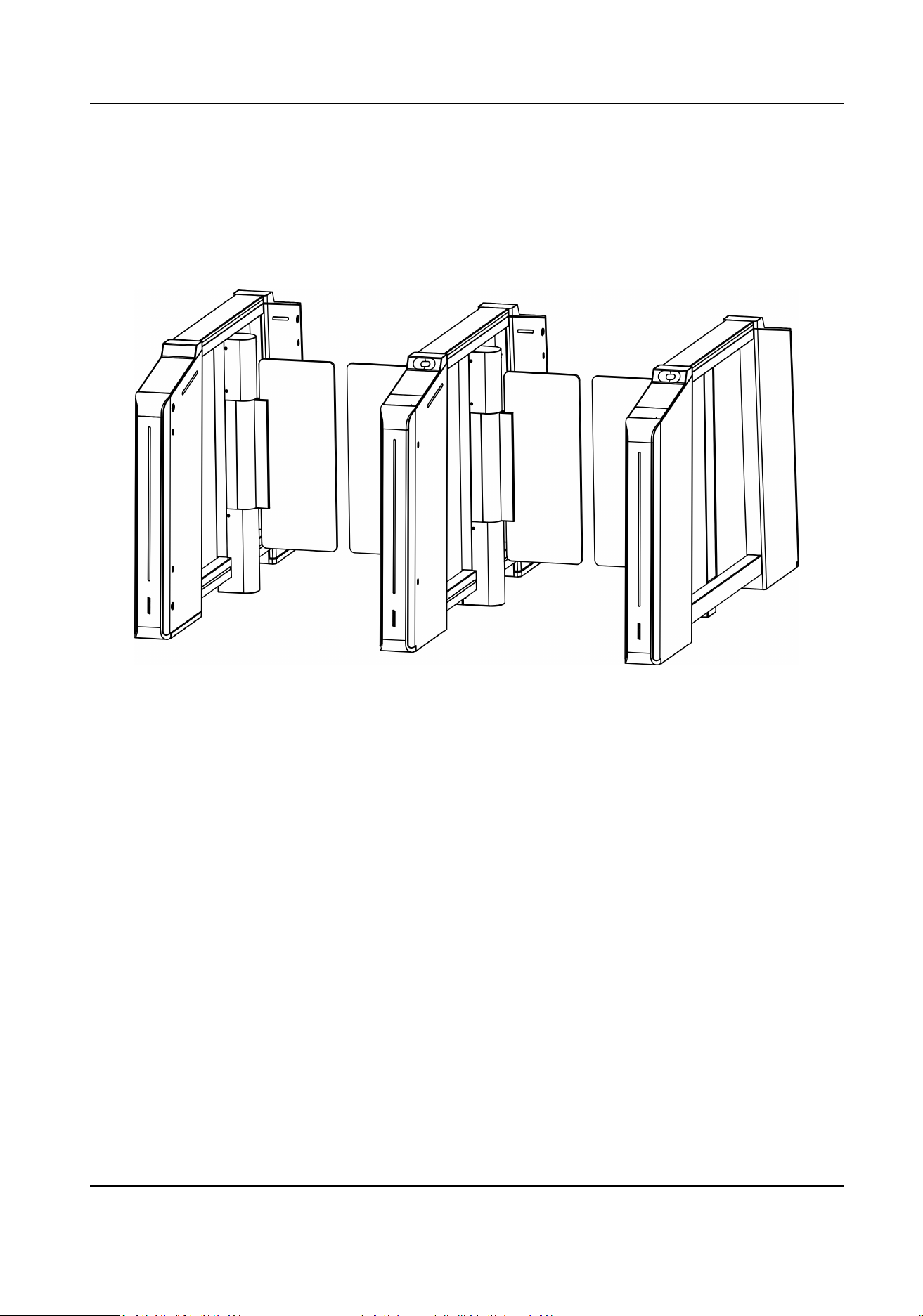
Chapter 1 Overview
1.1 Introducon
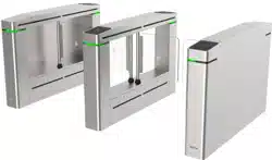
Figure 1-1 Appearance
The ap barrier with two barriers and 20 IR lights is designed to detect unauthorized passing from
the entrance or exit. By adopng the ap barrier integratedly with the access control system,
person should
authencate to pass through the lane via swiping IC or ID card, scanning QR code,
etc. It is widely used in aracons, stadiums, construcon sites, residences, etc.
1.2 Main Features
●
32-bit high-speed processor
●
IP address
conict detecon
●
Remote control and management
●
Online/oine operaon
●
Conguraon via local operaon, PC web and mobile web
●
TCP/IP network
communicaon
The communicaon data is specially encrypted to relieve the concern of privacy leak
●
Person authencaon
●
Permissions validaon and an-tailgang
●
Control mode, inducve mode, remaining open/closed mode and free passing mode selectable
Bidireconal (Entering/Exing) lane
DS-K3B631TX Series Swing Barrier User Manual
1

The barrier opening and closing speed can be congured according to the visitor ow
●
Single or mulple IR detector triggering
●
Opens/Closes barrier according to the schedule template
●
Cross controller
an-passback
●
The barrier will be locked or stop working when people are nipped
●
An-forced-accessing
The barrier will be locked automacally without open-barrier signal. It can bear the force of up
to 120 Nm
●
Self-detecon, Self-diagnoscs, and automac alarm
●
Audible and visual alarm will be triggered when
detecng intrusion, tailgang, reverse passing,
and climbing over barrier
●
Barrier is in free status when powered down; If the device is installed with lithium baery
(oponal), the barrier remains open when powered down
●
Fire alarm passing
When the re alarm is triggered, the barrier will be open automacally for emergency
evacuaon
●
Valid passing duraon sengs
System will cancel the passing permission if a person does not pass through the lane within the
valid passing duraon
●
Up to 10,0000 faces, up to 50,0000 cards and up to 100,000 events except can be added
●
Custom broadcasng content
●
LED indicates the entrance/exit and passing status
●
White indicators for card and QR code
authencaon;
Red and green arrow indicators;
Adjustable brightness and color of entrance light and side light
●
IR emergency mode and Custom An-pinch for Door Closing
DS-K3B631TX Series Swing Barrier User Manual
2
Chapter 2 Light Introducon
Descripon of light and how to set light via DIP switch.
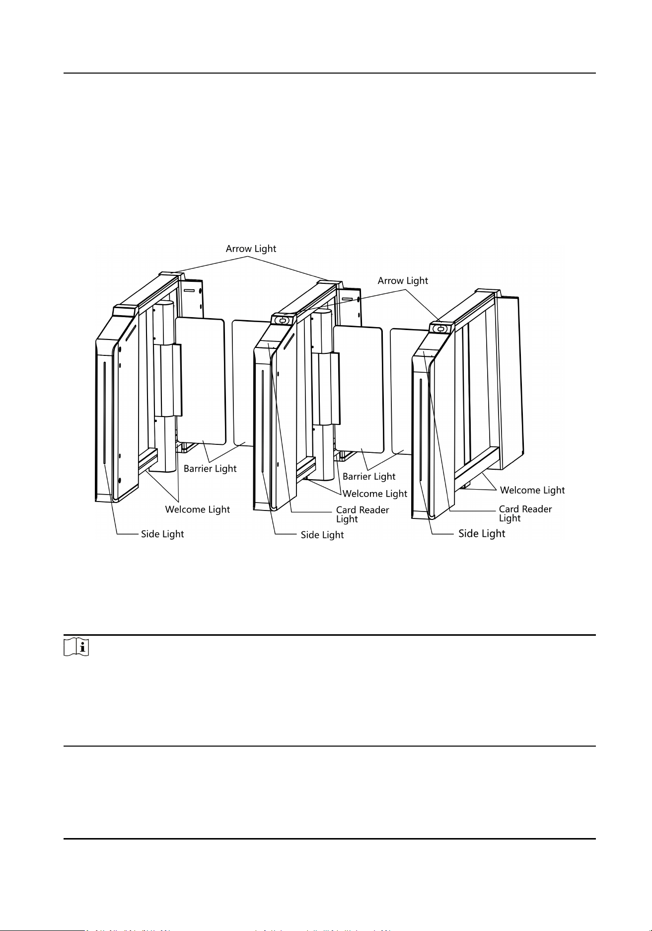
2.1 Light Descripon
Figure 2-1 Light Posion
Side Light
The side light indicates dierent status of the lane, including inducve, prohibited and
authencated passing.
Note
●
When the device detects people within 1.5 m, the side light will be ashing.
●
Only the right side light indicates the lane status.
●
Light stays blue: inducve mode
●
Light
ashes green: authencated passing
●
Light stays red: passing prohibited
DS-K3B631TX Series Swing Barrier User Manual
3
Barrier Light
The barrier light stays white by default. You can set the barrier light color at your needs.
The barrier light will not change color according to the lane status or authencaon results.
Card Reader Light
The card reader light will stay white when the device detects people approaching unl people pass
through.
Arrow Light
●
The arrow light stays o when the device is on standby mode.
●
The light on the right side will
ash green ready for authencaon.
●
The light on both le and right side will stay green for authencated passing.
●
The light on the right side will
ash red when authencaon fails.
Welcome Light
The welcome light stays white at the boom of the pedestal.
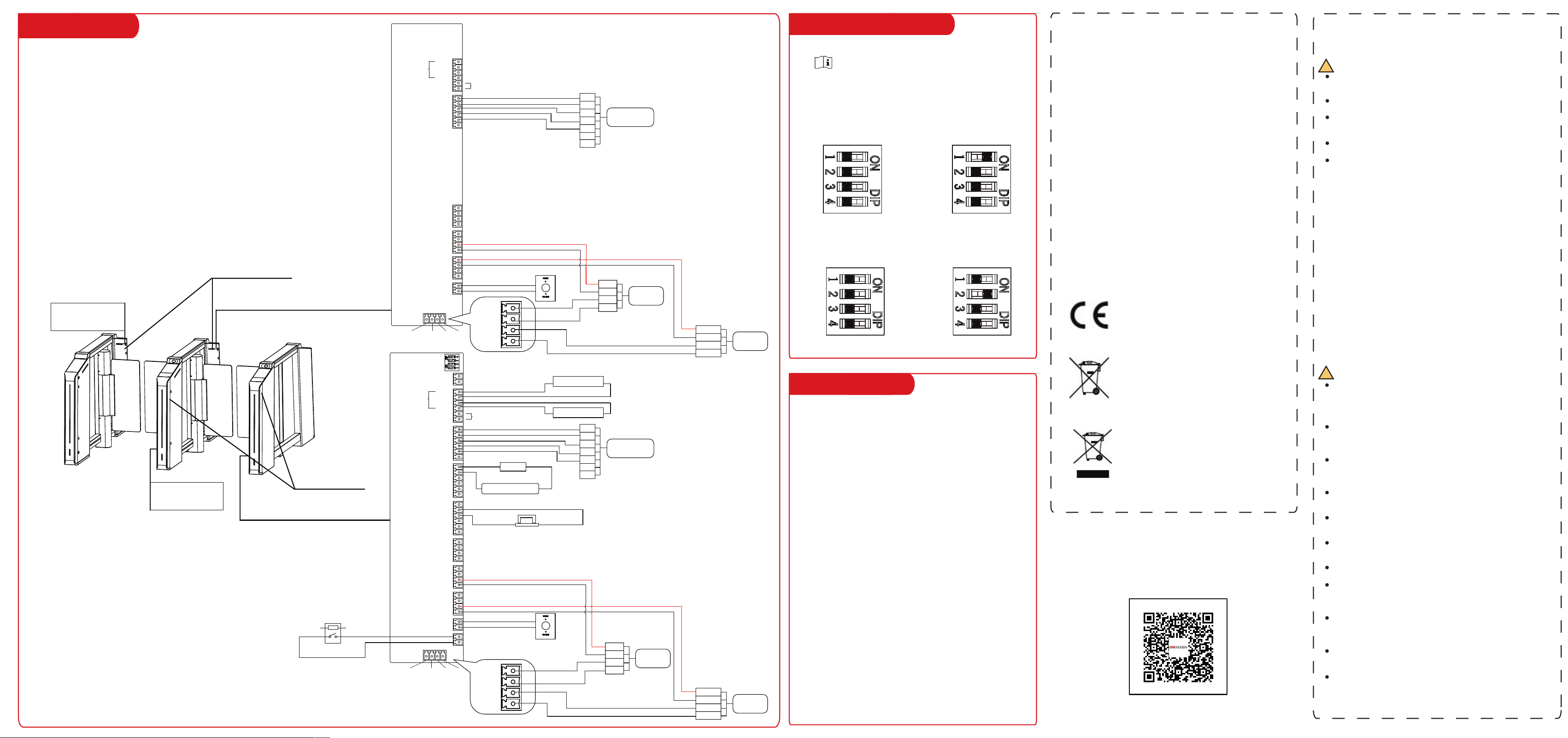
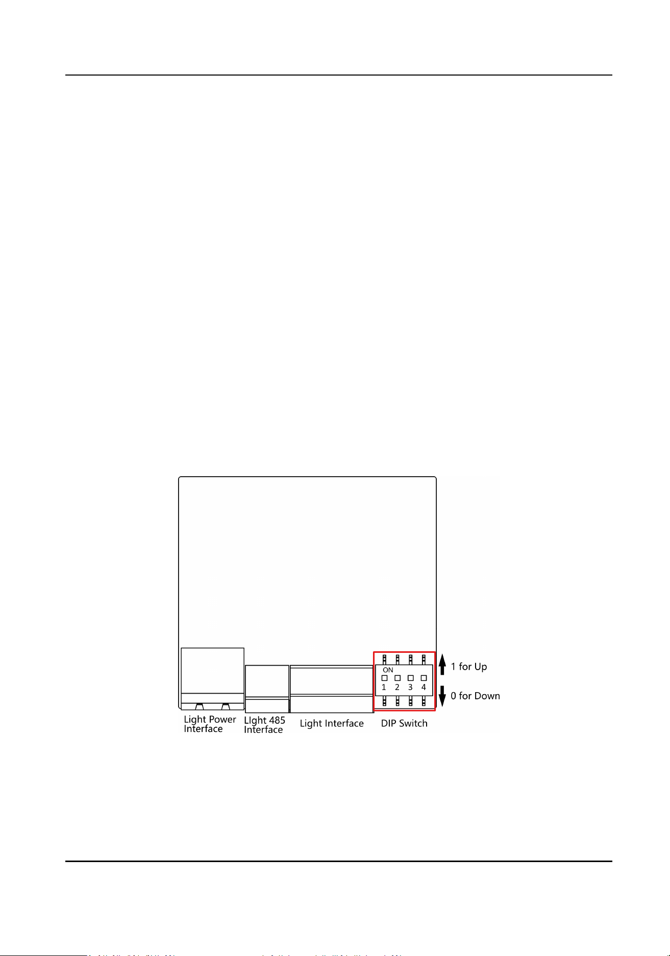
2.2 Side Light Board DIP Switch
Descripon
Congure the DIP switch address of side light.
Figure 2-2 Side Light Board DIP Switch
DS-K3B631TX Series Swing Barrier User Manual
4

Table 2-1 Light Board DIP Switch Descripon
Posion Address Value (Start from Le)
0 65 0 0000
1 81 1 1000
2 97 10 0100
3 113 11 1100
4 129 100 0010
5 130 101 1010
6 131 110 0110
7 132 111 1110
8 133 1000 0001
9 134 1001 1001
10 135 1010 0101
11 136 1011 1101
12 137 1100 0011
13 138 1101 1011
14 139 1110 0111
15 140 1111 1111
DS-K3B631TX Series Swing Barrier User Manual
5
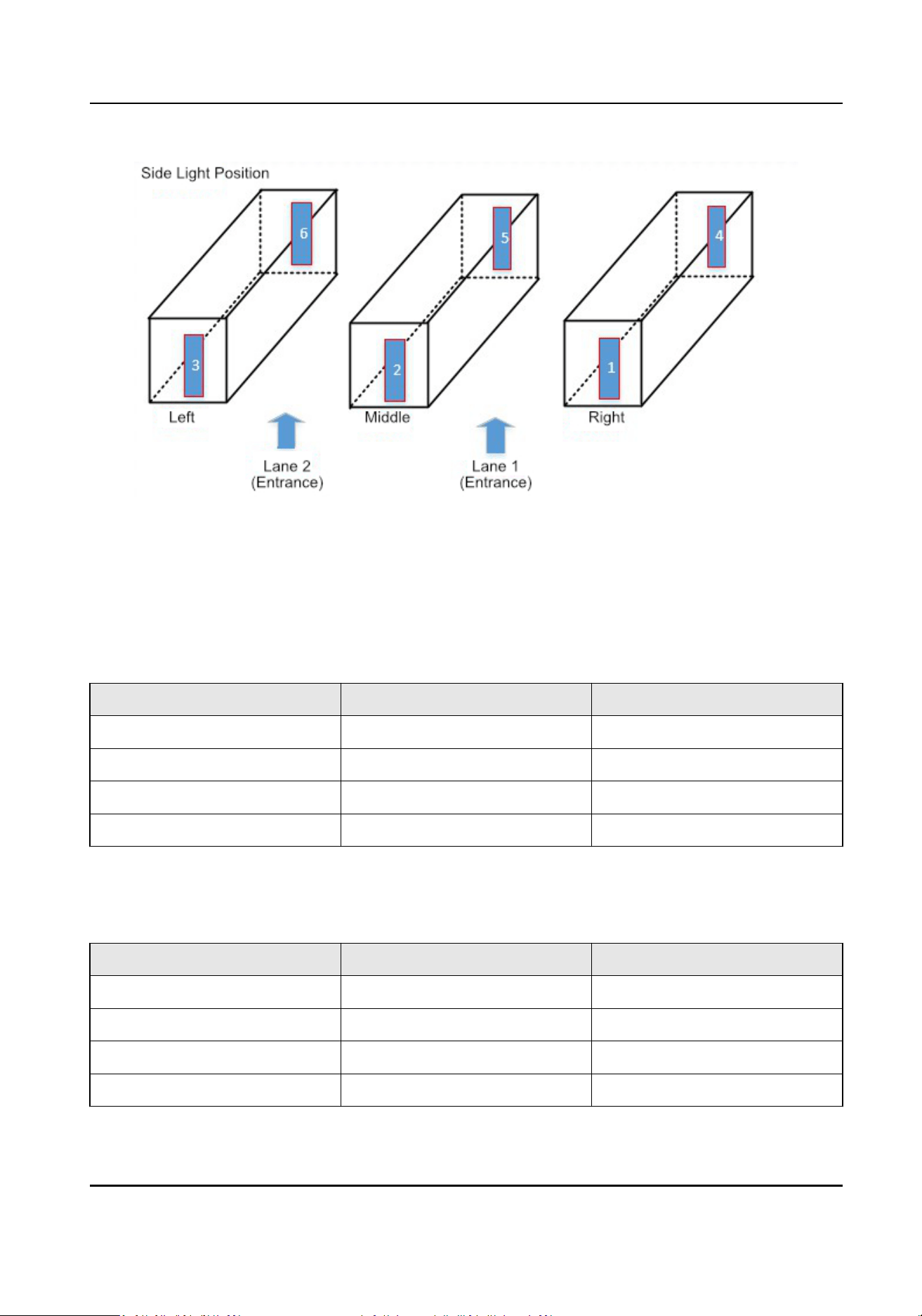
Figure 2-3 Side Light Posion
Single-Lane Scenario
In single-lane scenario, the side lights are located at the posion of NO. 1, 3, 4, 6. Side light No. 1 is
near the main user extended interface board.
Table 2-2 Single-Lane DIP Switch
Descripon
Posion Address Value
No. 1 65 0000
No. 3 113 1100
No. 4 81 1000
No. 6 97 0100
Dual-Lane Scenario
Table 2-3 Dual-Lane DIP Switch Descripon
Posion Address Value
No. 1 65 0000
No. 2 65 0000
No. 3 113 1100
No. 4 81 1000
DS-K3B631TX Series Swing Barrier User Manual
6

Posion Address Value
No. 5 97 0100
No. 6 97 0100
DS-K3B631TX Series Swing Barrier User Manual
7

Chapter 3 System Wiring
The preparaon before installaon and general wiring.
Steps
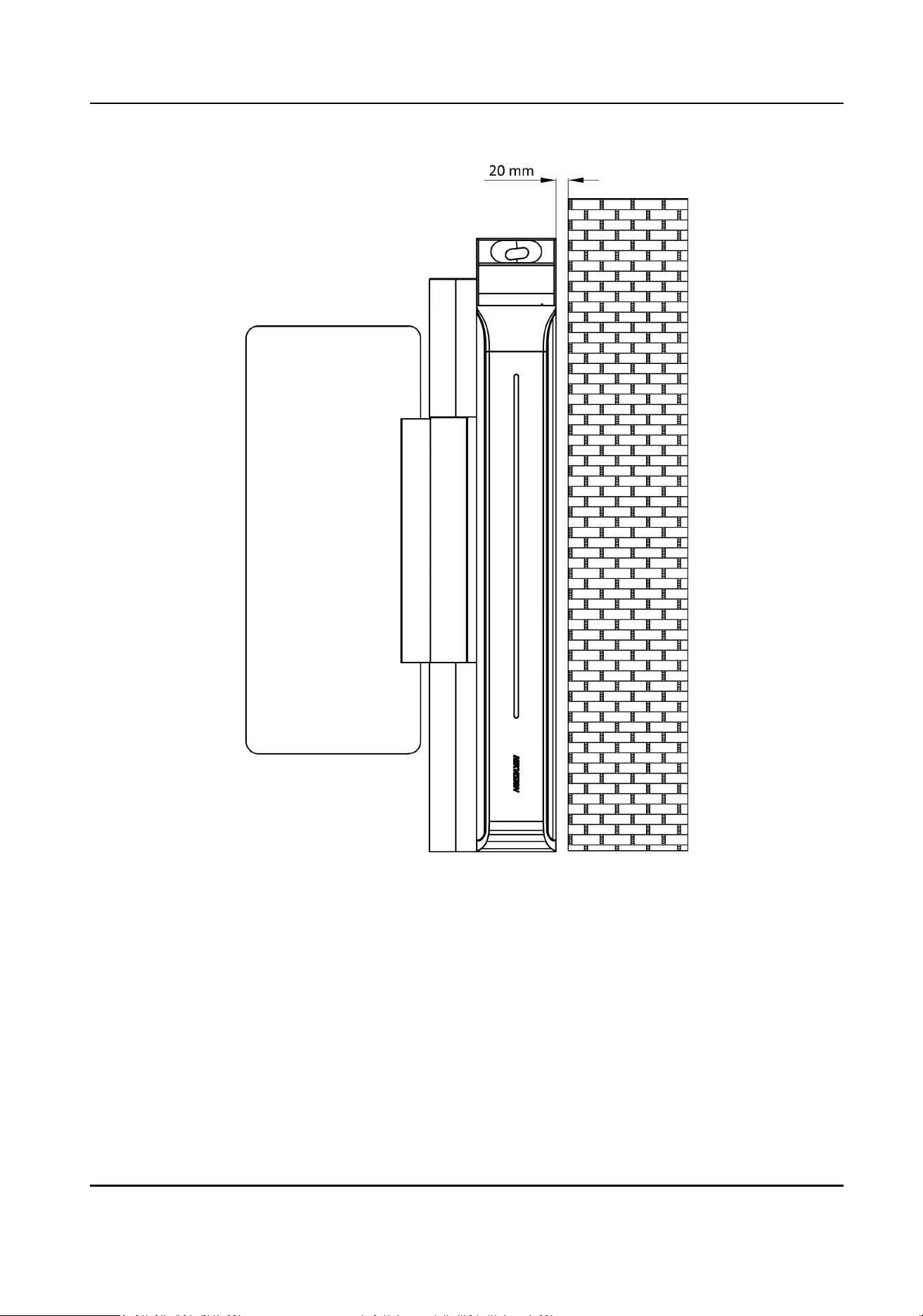
Note
●
The device should be installed on the concrete surface or other non-ammable surfaces.
●
If the installaon area is too close to the wall, make sure the distance between the pedestal and
the wall should be no less than 20 mm, or you cannot open the pedestal's top panel.
DS-K3B631TX Series Swing Barrier User Manual
8
●
The dimension is as follows.
DS-K3B631TX Series Swing Barrier User Manual
9
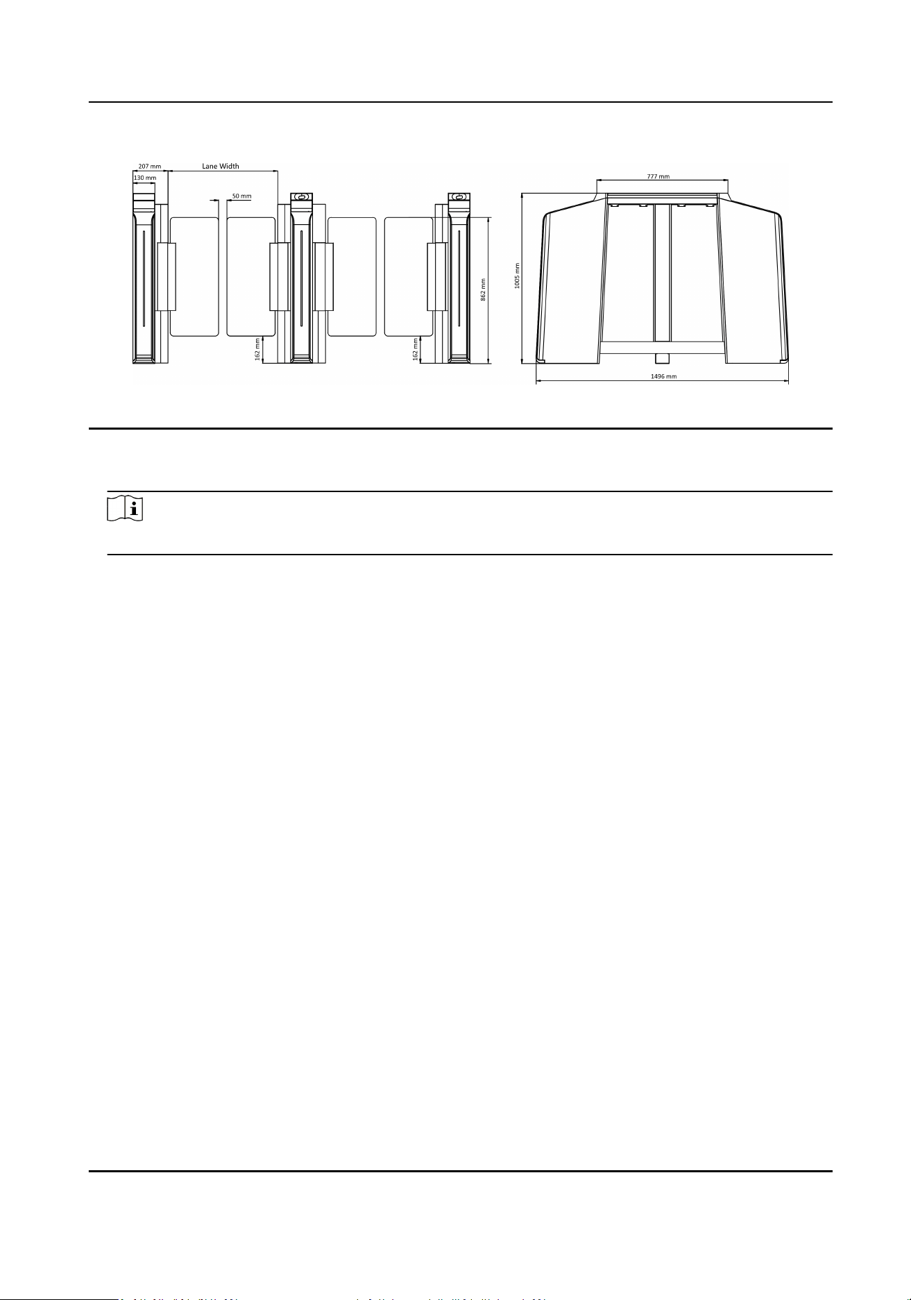
Figure 3-1 Dimension
1.
Draw a central line on the installaon surface of the le or right pedestal.
2.
Draw other parallel lines for installing the other pedestals.
Note
The distance between the nearest two line is L + 284 mm. L represents the lane width.
3.
Slot on the installaon surface and dig installaon holes according to the hole posion diagram.
Use 6 expansion bolts for each pedestal.
DS-K3B631TX Series Swing Barrier User Manual
10
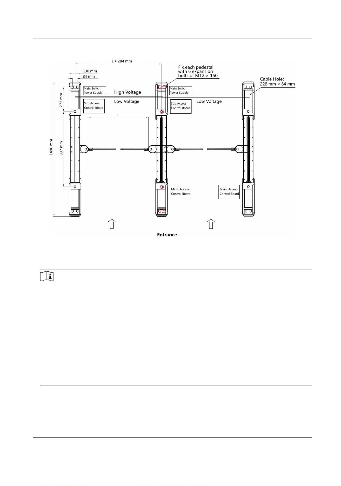
Figure 3-2 Hole Posion Diagram
4.
Bury cables. Each lane buries 1 high voltage cable and 1 low voltage cable. For details, see the
system wiring diagram in step 3.
Note
●
High voltage: AC power input
Low voltage: interconnecng cable (communicaon cable and 24 V power cable) and network
communicaon cable
●
The supplied
interconnecng cable length is 3 m.
●
The suggested inner diameter of the low voltage conduit is larger than 30 mm.
●
If you want to bury both of the AC power cord and the low voltage cable, the two cables
should be in separated conduits to avoid interference.
●
If more peripherals are required to connect, you should increase the conduit diameter or bury
another conduit for the external cables.
●
The external AC power cord should be double-insulated.
●
The
interconnecng cable can be CAT5e and CAT6e network cable is suggested for PC
connecon.
DS-K3B631TX Series Swing Barrier User Manual
11
Chapter 4 Installaon
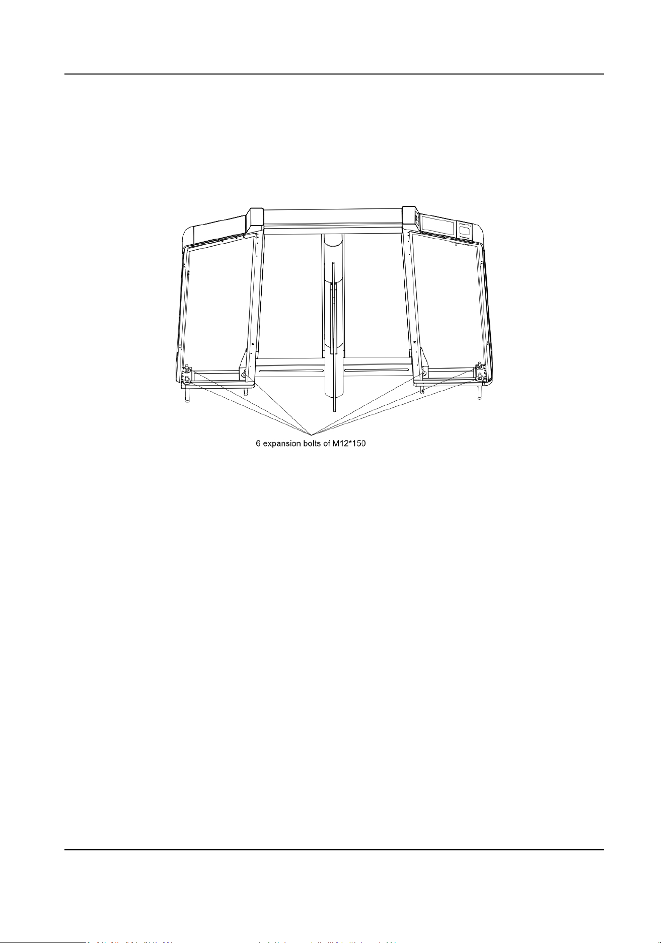
1. Aer system wiring, put the pedestals on the proper posion and x each pedestal with 6
expansion bolts.
Figure 4-1 Expansion Bolts posion
2. Open the side panel with the key for cable wiring or device maintenance.
DS-K3B631TX Series Swing Barrier User Manual
12
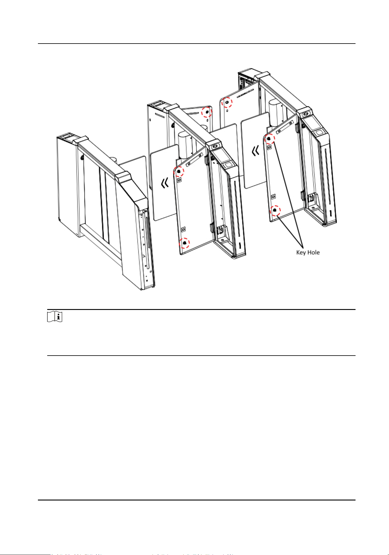
Figure 4-2 Key Hole
Note
For le and right pedestals, both side panels opens toward the passing lane. For middle
pedestals, the side panel at the entrance opens toward the le passing lane, and the other side
panel at the exit opens toward right.
DS-K3B631TX Series Swing Barrier User Manual
13
Chapter 5 General Wiring
Note
●
When you should maintain or disassemble the high voltage modules, you should remove the
enre high voltage modules and maintain it outside the turnsle. You should unplug the cables
that connected to the peripherals before maintenance to avoid destroy of the device.
●
When disassembling the high voltage module, you should disconnect the power to avoid injury.
●
If only wiring is needed without maintenance, do not remove the high voltage modules.
●
The switch and the main lane control board are already connected. The 14 AWG cable to
connect between the AC electric supply and the switch should be purchased separately.
●
2
interconnecng cables are supplied: 24 V Power Cable and Communicaon Cable.
24 V Power Cable: 5 m long, which is in the middle and right pedestal.
Communicaon Cable: 4 m long, CAT5e, which is in the package of middle and right pedestal.
5.1 Components Introducon
By default, basic components of the turnsle are connected well. The pedestals can communicate
by wiring the interconnecng cables. And the turnsle supports wiring the AC electric supply for
the whole system's power supply.
Note
The voltage uctuaon of the electric supply is between 100 VAC and 260 VAC, 50 to 60 Hz.
The picture displayed below describes each component's posion on the turnsle.
Note
The diagram is for reference only.
DS-K3B631TX Series Swing Barrier User Manual
14
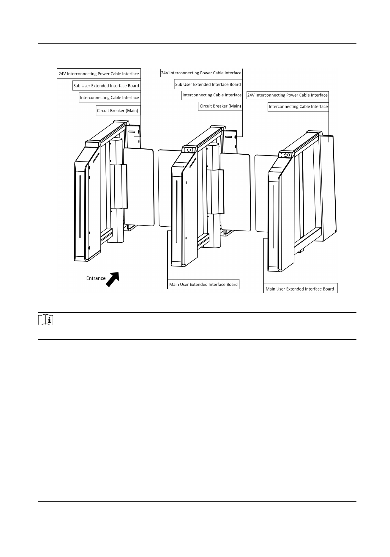
Figure 5-1 Components Diagram
Note
For details about wiring arrangement, refers to the actual device.
The picture displayed below describes the IR adapter and the IR sending/receiving module and
their corresponding number on the pedestal.
DS-K3B631TX Series Swing Barrier User Manual
15
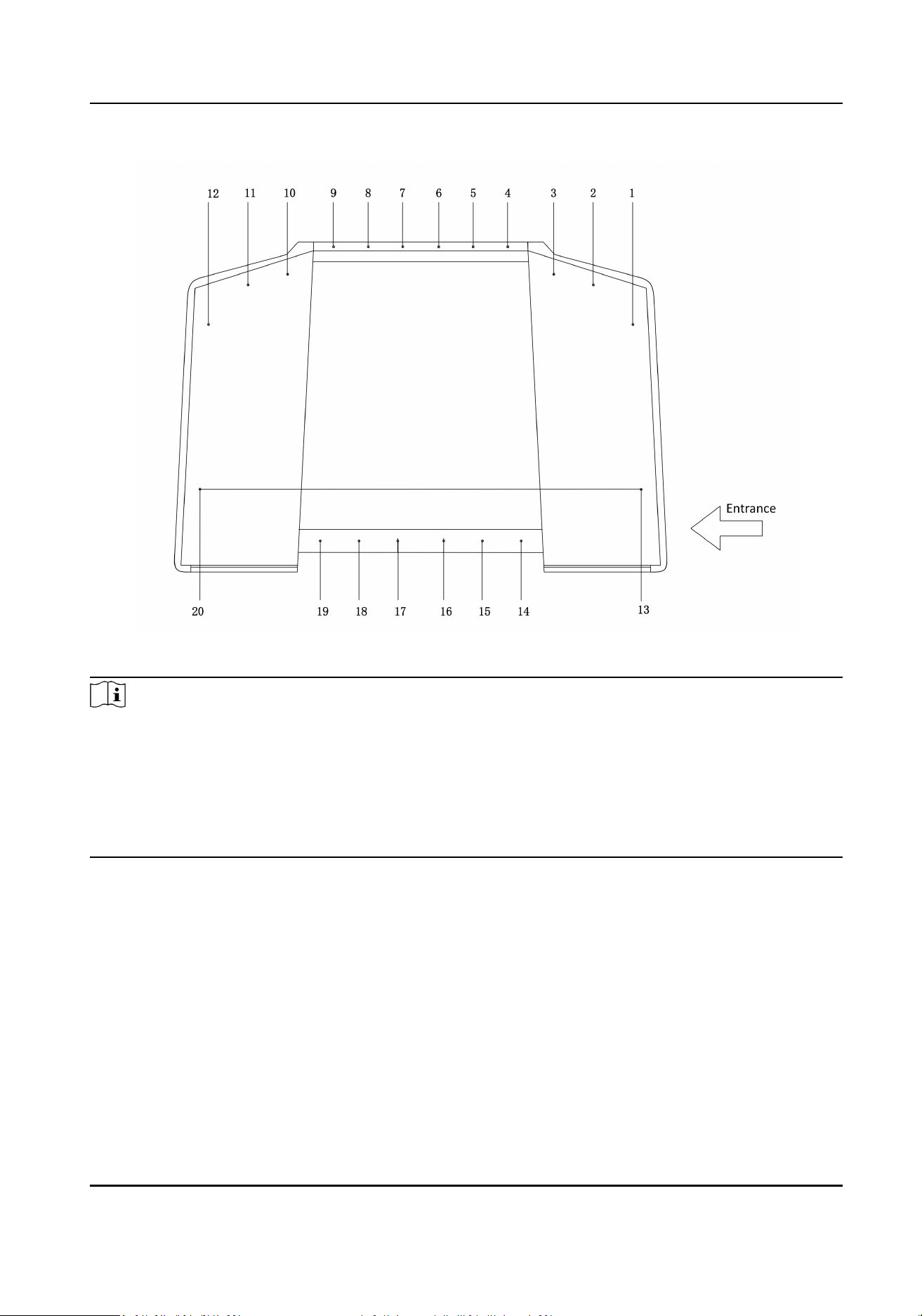
Figure 5-2 IR Modules
Note
●
For details about wiring arrangement, refers to the actual device.
●
If the turnsle contains two lanes, standing at the entrance posion, the IR modules on the le
pedestal are the IR sending modules. The IR modules on the right pedestal are the IR receiving
modules. The IR modules on the
le side of the middle pedestal are the IR receiving modules,
while the IR modules on the right side of the middle pedestal are the IR sending modules.
●
Safety
Instrucons can be viewed on the middle panel inside the pedestal.
5.2 Wiring
3 interconnecng cables are contained in the package:
24 VAC Power
Interconnecng Cable
The 24 VAC Power Interconnecng Cable of 12AWG is placed inside of the right/middle pedestal
at the exit direcon.
Lane Control Interconnecng Cable
DS-K3B631TX Series Swing Barrier User Manual
16
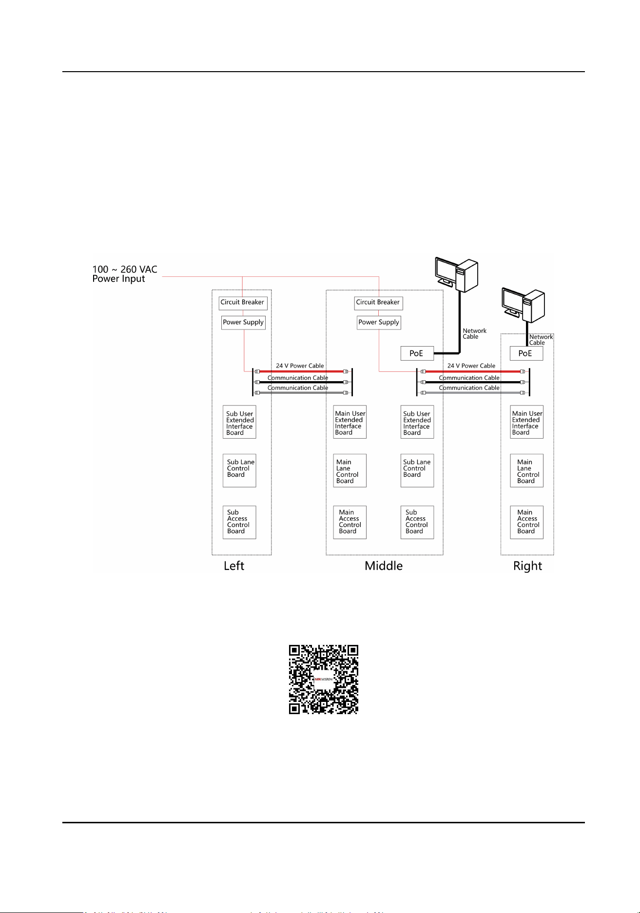
The gray CAT5e cable is used for connecon between main lane control board and sub lane
control board, and is placed inside of the package of the right/middle pedestal. You need to plug
the cable into the gray adaptor.
Access Control Interconnecng Cable
The black CAT5e cable is used for connecon between main access control board and sub access
control board, and is placed inside of the package of the right/middle pedestal. You need to plug
the cable into the black adaptor.
The
interconnecng wiring diagram is as follows:
Figure 5-3 Interconnecng Wiring
Scan the QR code to watch the unboxing and wiring guide video.
DS-K3B631TX Series Swing Barrier User Manual
17
5.3 Terminal Descripon
The lane controller contains main lane controller and sub lane controller, which controls the IR
beams, motor, and other components' work.
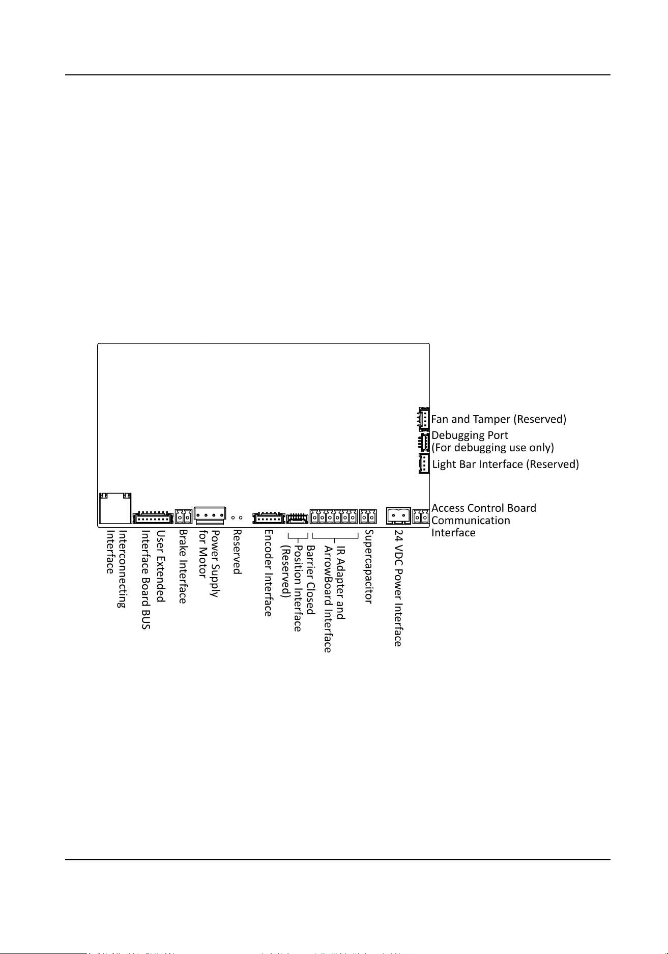
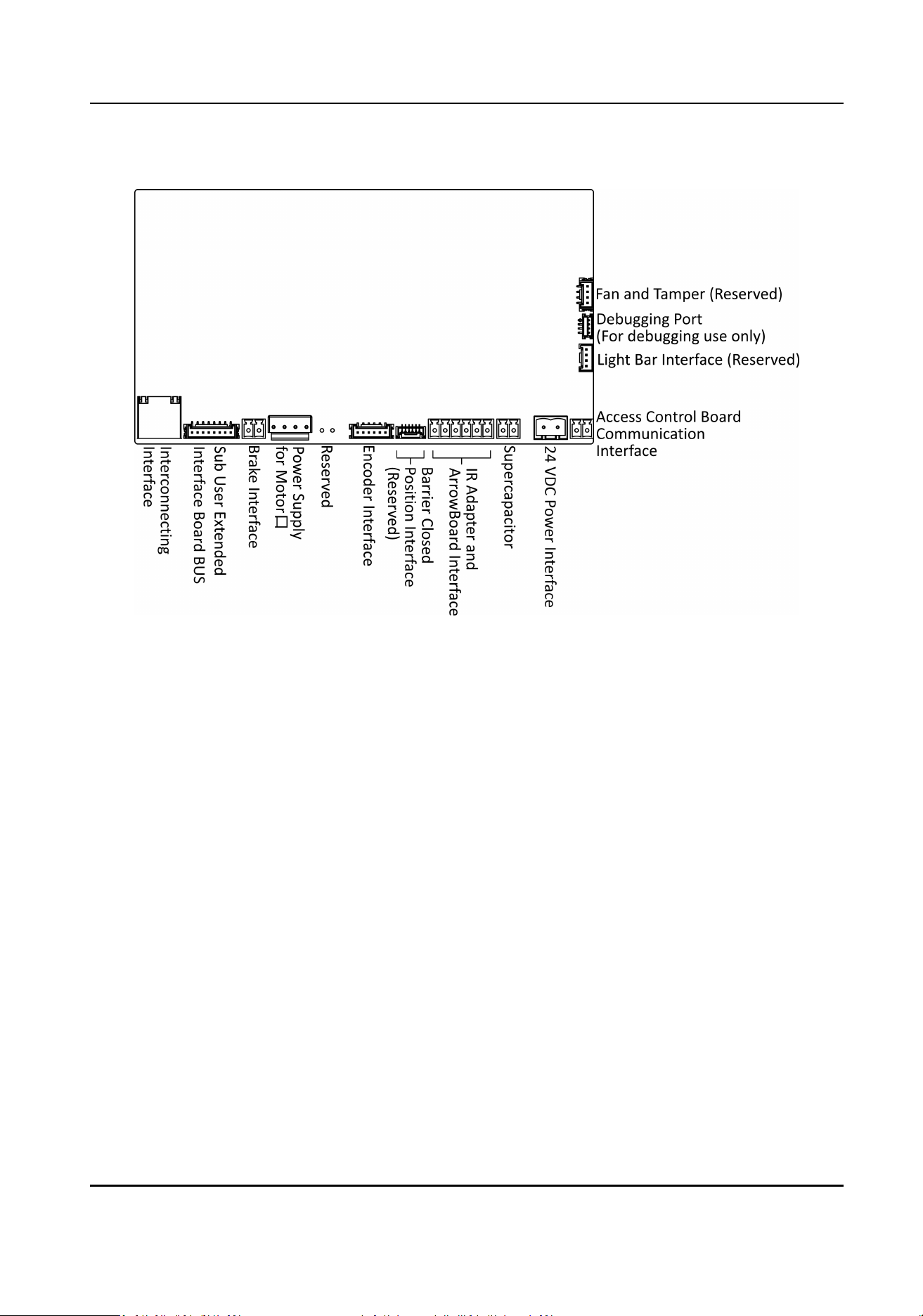
5.3.1 Main Lane Control Board Terminal Descripon
The main lane control board contains debugging port, access control board communicaon
interface, power interface, supercapacitor, IR adapter and ArrowBoard interface, encoder interface,
power supply for motor, brake interface, user extended interface board BUS, and
interconnecng
interface.
The picture displayed below is the main control board diagram.
Figure 5-4 Main Lane Control Board Terminal
5.3.2 Sub Lane Control Board Terminal
Descripon
The sub lane control board contains debugging port, access control board communicaon
interface, power interface, supercapacitor, IR adapter and ArrowBoard interface, encoder interface,
power supply for motor, brake interface, sub user extended interface board BUS and
interconnecng interface.
DS-K3B631TX Series Swing Barrier User Manual
18
The picture displayed below is the sub control board diagram.
Figure 5-5 Sub Lane Control Board Terminal
5.3.3 Main Access Control Board Terminal
Descripon
The main access control board contains screen adapter interface, sensor interface, loudspeaker
interface, IR light interface, user extended interface board and lane control board
communicaon
interface, antenna interface, network switch interface, sub access control board interface, power
interface, card reader board interface, TF card slot,
inializaon buon, debugging port and USB
ash drive interface.
The picture displayed below is the main access control board diagram.
DS-K3B631TX Series Swing Barrier User Manual
19
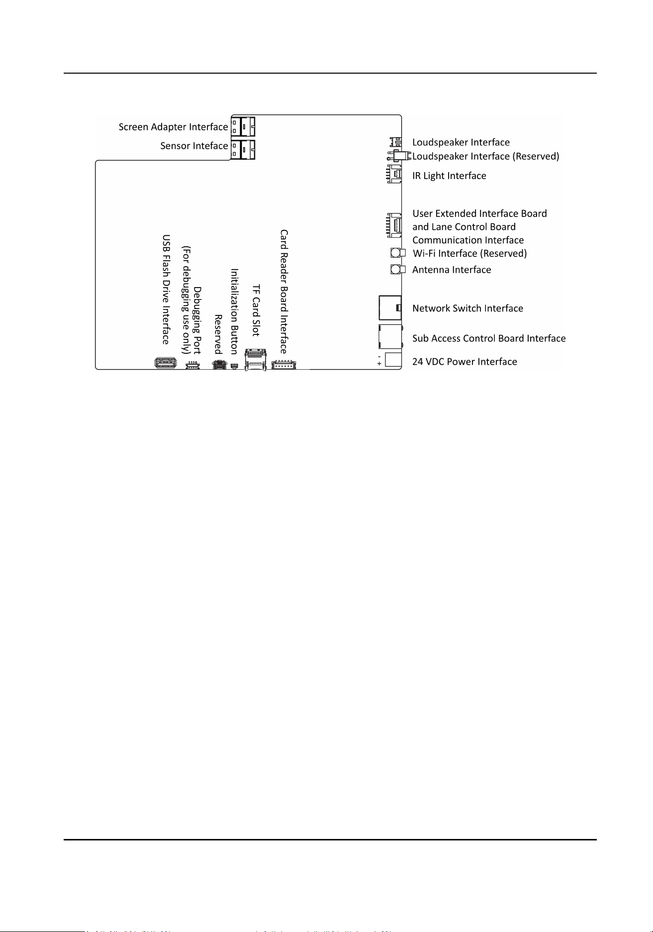
Figure 5-6 Main Access Control Board Terminal
5.3.4 Sub Access Control Board Terminal
Descripon
The sub access control board contains screen adapter interface, sensor interface, loudspeaker
interface, IR light interface, user extended interface board and lane control board
communicaon
interface, sub access control board interface, power interface, card reader board interface, TF card
slot, inializaon buon, debugging port and USB ash drive interface.
The picture displayed below is the sub access control board diagram.
DS-K3B631TX Series Swing Barrier User Manual
20
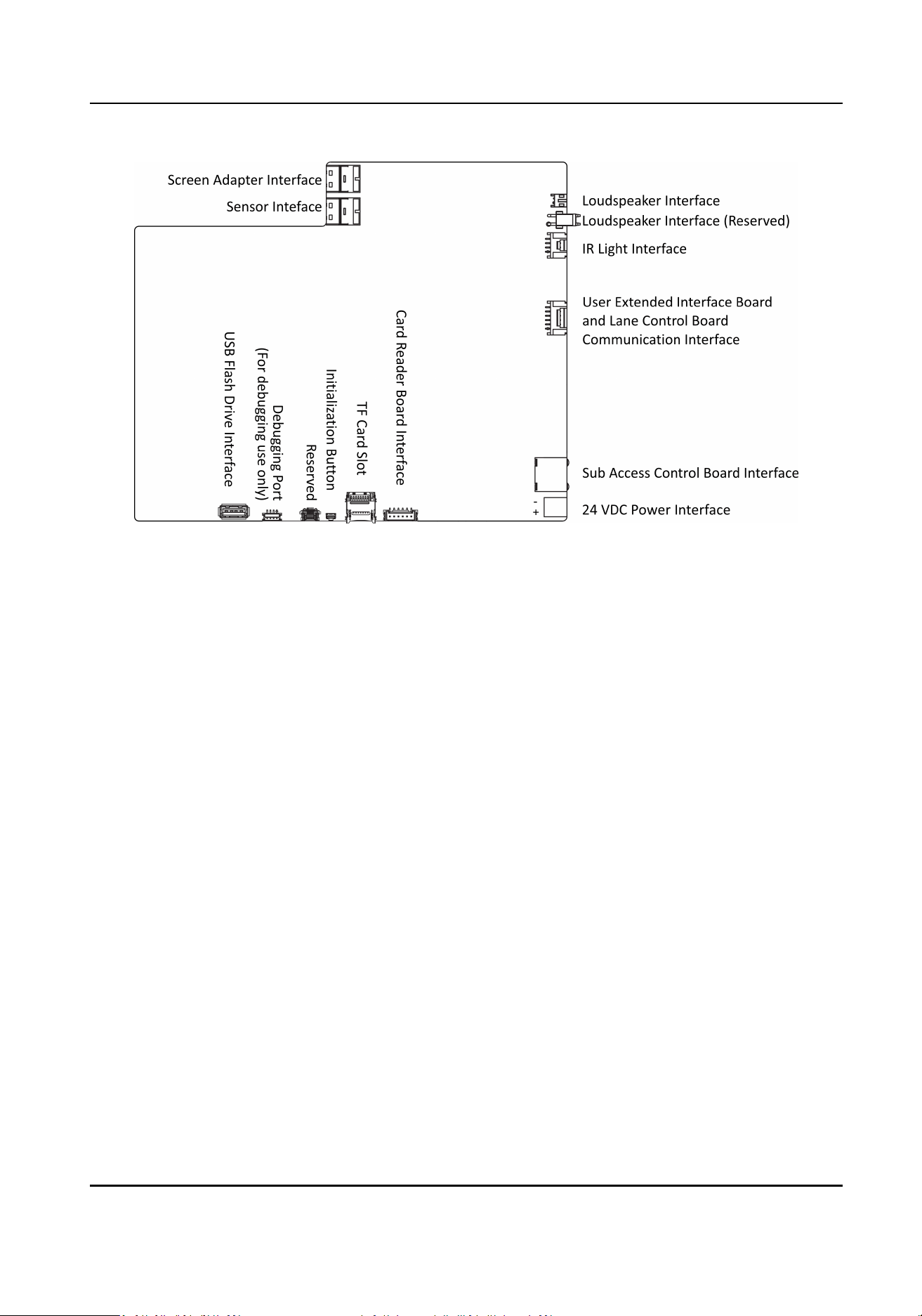
Figure 5-7 Sub Access Control Board Terminal
DS-K3B631TX Series Swing Barrier User Manual
21
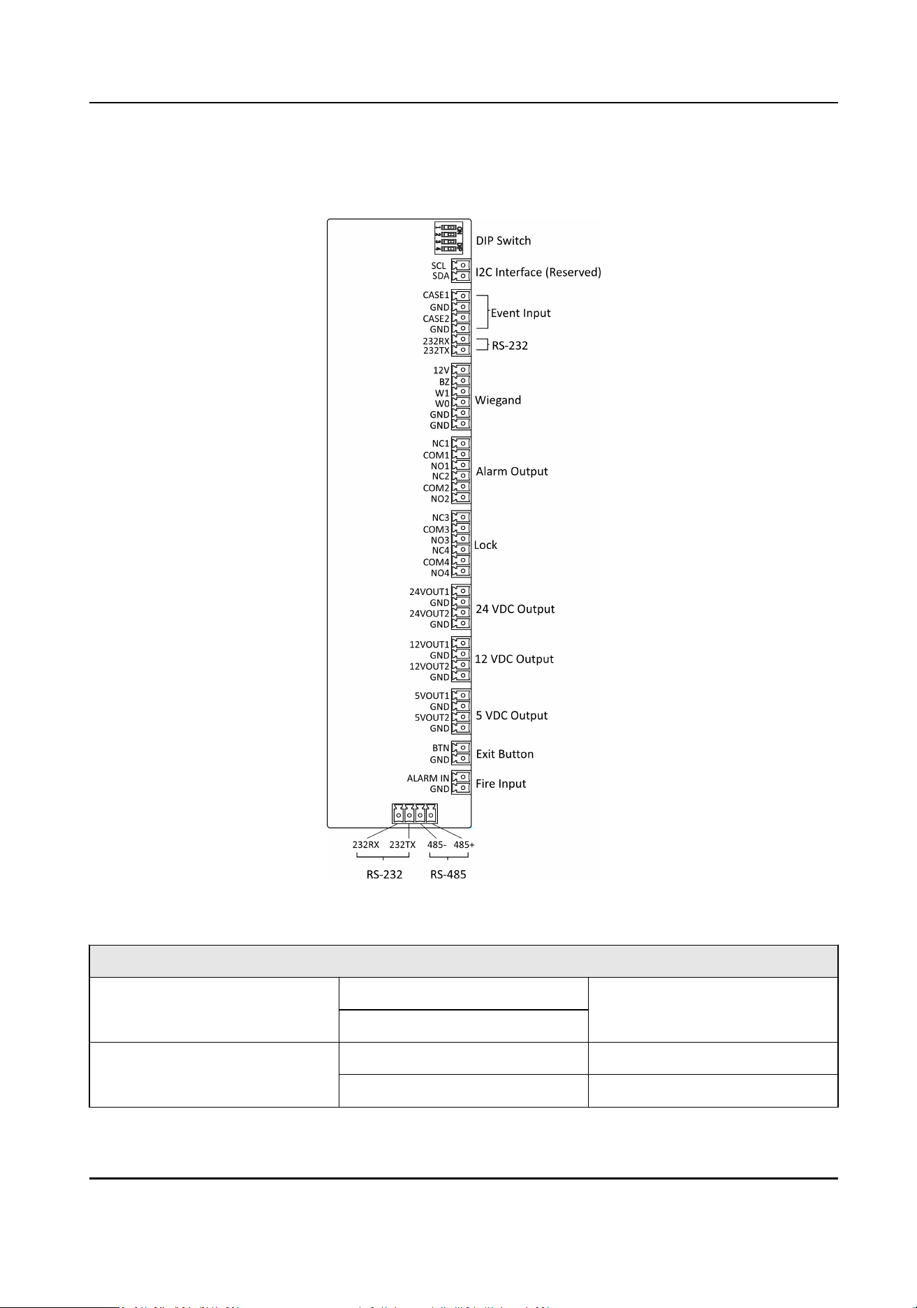
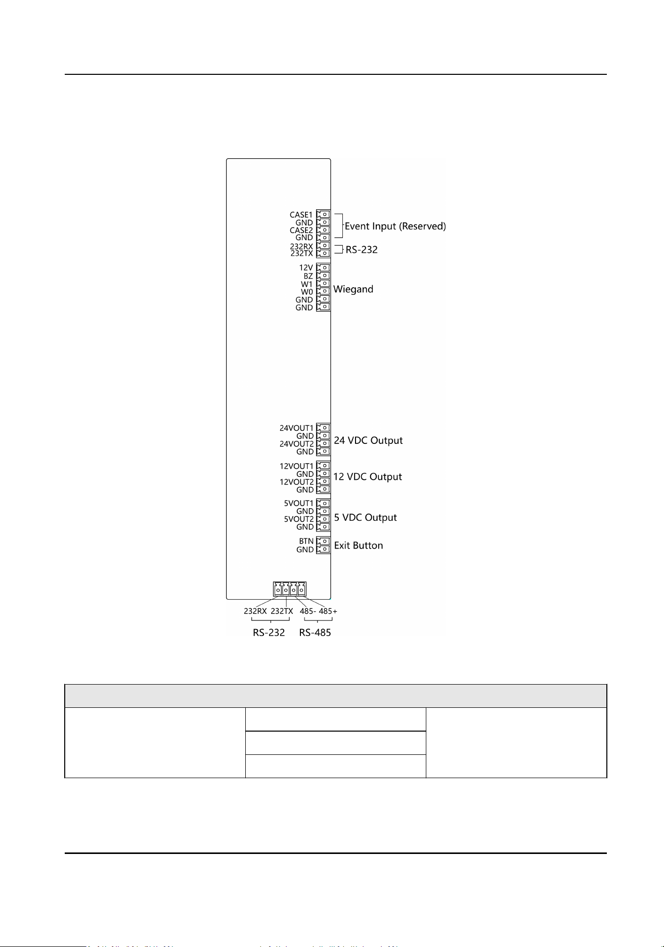
5.3.5 Main User Extended Interface Board
Figure 5-8 Main User Extended Interface
Main User Extended Interface
Descripon
I2C Interface SCL Reserved
SDA
Event Input CASE1 Event Alarm Input 1
CASE2 Event Alarm Input 2
DS-K3B631TX Series Swing Barrier User Manual
22

Main User Extended Interface Descripon
GND Grounding
RS-232 Interface 232RX Connect to Card Reader RS-
232RX
232TX Connect to Card Reader RS-
232TX
RS-485 485- Connect to Card Reader RS485-
485+ Connect to Card Reader
RS485+
Wiegand Card Reader 12 V 12 VDC Power Input
BZ Card Reader Buzzer Control
Output
W0 Wiegand Head Read Data Input
Data0
W1 Wiegand Head Read Data Input
Data1
GND Grounding
Alarm Output NO/NC1 Alarm Output Relay 1 (Dry
Contact)
COM1
NO/NC2 Alarm Output Relay 2 (Dry
Contact)
COM2
Lock NO/NC3 Door Relay Output (Dry
Contact)
COM3
NO/NC4
COM4
Power Output 1 24VOUT1 24 VDC Power Output 1
24VOUT2 24 VDC Power Output 2
GND Grounding
Power Output 2 12VOUT1 12 VDC Power Output 1
12VOUT2 12 VDC Power Output 2
GND Grounding
DS-K3B631TX Series Swing Barrier User Manual
23

Main User Extended Interface Descripon
Power Output 3 5VOUT1 5 VDC Power Output 1
5VOUT1 5 VDC Power Output 2
GND Grounding
Exit Buon BTN Door Signal Input
GND Grounding
Fire Input ALARM IN Fire Alarm Input
GND Grounding
DS-K3B631TX Series Swing Barrier User Manual
24
5.3.6 Sub User Extended Interface Board
Figure 5-9 Sub User Extended Interface
Main User Extended Interface
Descripon
Event Input CASE1 Reserved
CASE2
GND
DS-K3B631TX Series Swing Barrier User Manual
25

Main User Extended Interface Descripon
RS-232 Interface 232RX Connect to Card Reader RS-
232RX
232TX Connect to Card Reader RS-
232TX
RS-485 485- Connect to Card Reader RS485-
485+ Connect to Card Reader
RS485+
Wiegand Card Reader 12 V 12 VDC Power Input
BZ Card Reader Buzzer Control
Output
W0 Wiegand Head Read Data Input
Data0
W1 Wiegand Head Read Data Input
Data1
GND Grounding
Power Output 1 24VOUT1 24 VDC Power Output 1
24VOUT2 24 VDC Power Output 2
GND Grounding
Power Output 2 12VOUT1 12 VDC Power Output 1
12VOUT2 12 VDC Power Output 2
GND Grounding
Power Output 3 5VOUT1 5 VDC Power Output 1
5VOUT1 5 VDC Power Output 2
GND Grounding
Exit Buon BTN Door Signal Input
GND Grounding
DS-K3B631TX Series Swing Barrier User Manual
26
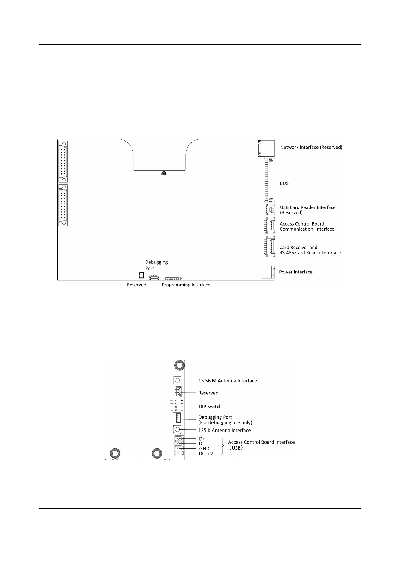
5.3.7 User Core Board Terminal Descripon
The user core board terminal contains network interface, BUS, USB card reader interface, access
control board
communicaon interface, card receiver and RS-485 card reader interface, power
interface, programming interface and debugging port.
The picture displayed below is the user core board diagram.
Figure 5-10 User Core Board Terminal
5.3.8 Card Reader Board Terminal
Descripon
The card reader board can be connected to the access control board via USB interface.
Figure 5-11 Card Reader Board
DS-K3B631TX Series Swing Barrier User Manual
27
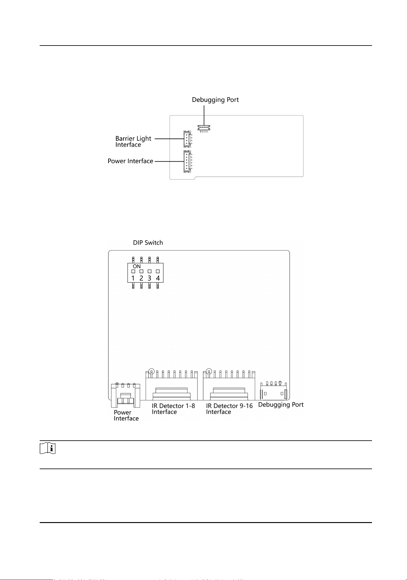
5.3.9 Arrow Light Board Terminal Descripon
Figure 5-12 Arrow Light Board
5.3.10 Upper IR Adapter Board Terminal
Descripon
Figure 5-13 Upper IR Adapter Board
Note
Set DIP switch 1 to ON side.
DS-K3B631TX Series Swing Barrier User Manual
28
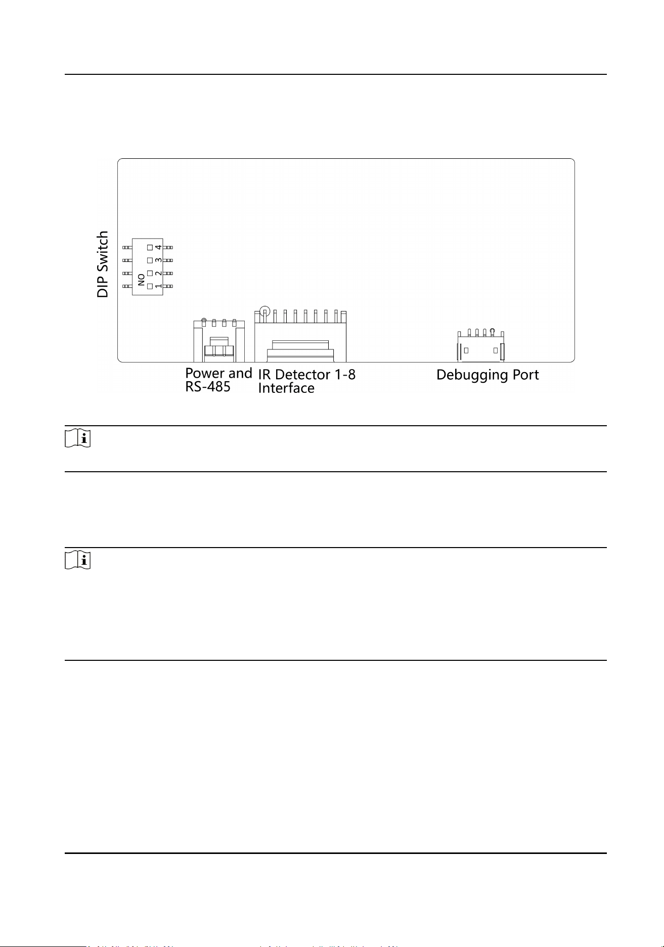
5.3.11 Lower IR Adapter Board Terminal Descripon
Figure 5-14 Lower IR Adapter Board
Note
Set DIP switch 2 to ON side.
5.3.12 RS-485 Wiring
The main and sub user extended interface board each has one RS-485 interface.
Note
●
If connecng the RS-485 with a card reader, by default, the DIP switch of the card reader is: 1 for
entrance, and 4 for exit.
●
If there are other RS-485 devices connecng, the ID of the RS-485 cannot be conicted.
●
The connected 12 V power interface for the face
recognion terminal cannot be connected with
other 12 V devices.
DS-K3B631TX Series Swing Barrier User Manual
29
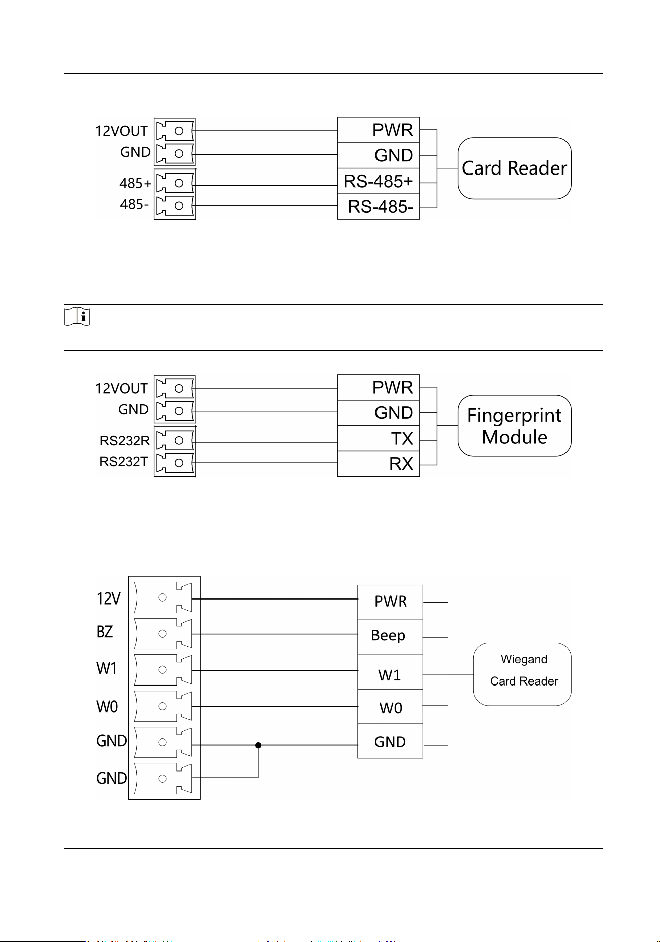
Figure 5-15 RS-485 Wiring
5.3.13 RS-232 Wiring
Note
The main and sub user extended interface board each has two RS-232 interface.
Figure 5-16 RS-232 Wiring
5.3.14 Wiegand Wiring
DS-K3B631TX Series Swing Barrier User Manual
30
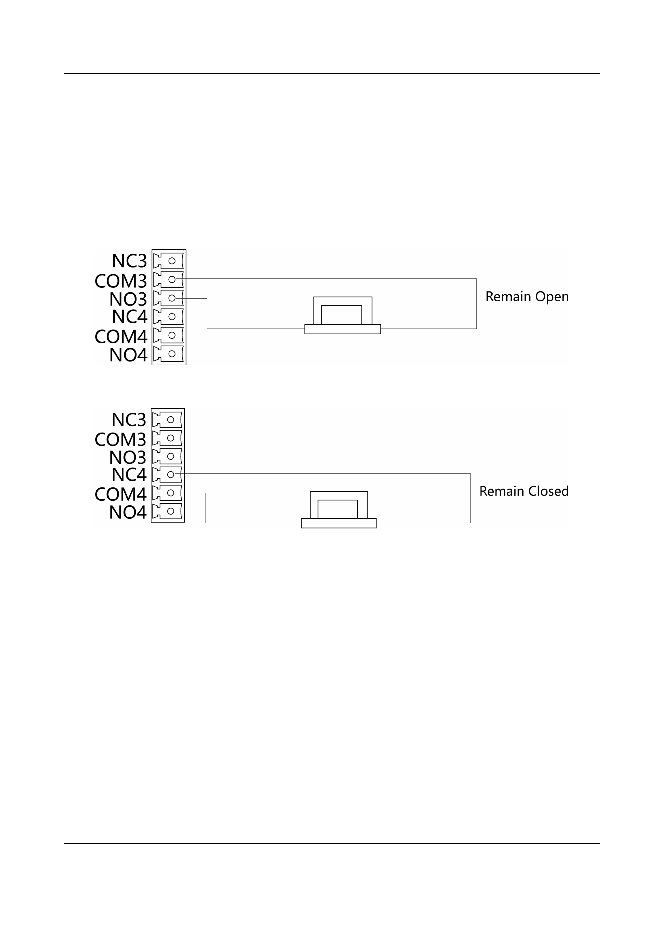
5.3.15 Barrier Control Wiring
According to the barrier control interfaces and the internal relays, the device provides 2 groups of
the barrier control signals on the main user extended interface board, including 1 remaining open
interface and 1 remaining closed interface.
NO: Remaining Open
NC: Remaining Closed
Figure 5-17 Barrier Control Wiring 1
Figure 5-18 Barrier Control Wiring 2
5.3.16 Alarm Output Wiring
On the main user extended interface board, you can wire the alarm output interface.
According to the alarm output interfaces and the internal relays, the device provides 2 groups of
the alarm output control signals, including 1 remaining open interface and 1 remaining closed
interface.
NO: Remaining Open
NC: Remaining Closed
DS-K3B631TX Series Swing Barrier User Manual
31
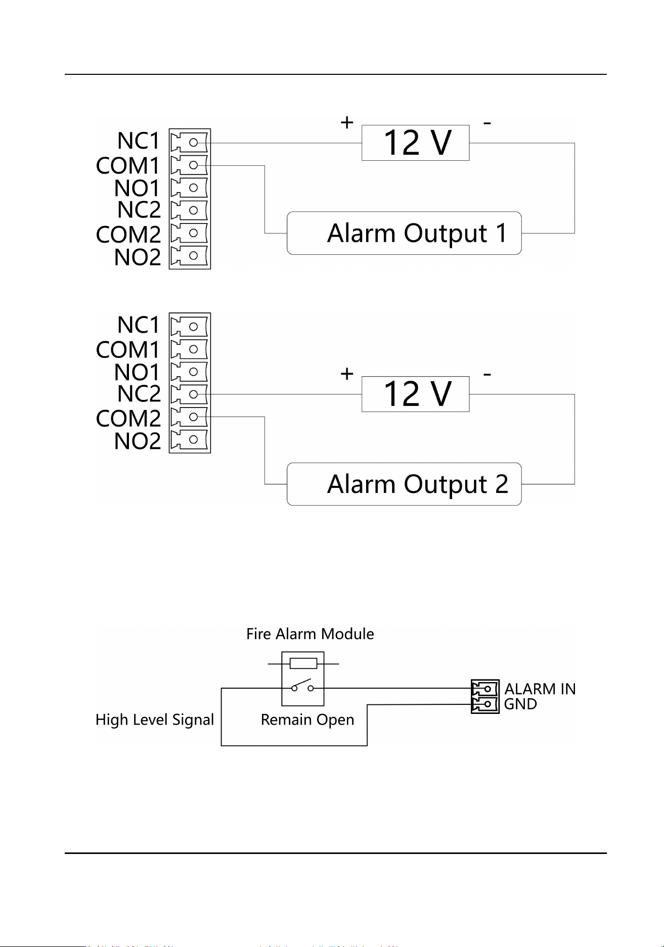
Figure 5-19 Alarm Output Wiring 1
Figure 5-20 Alarm Output Wiring 2
5.3.17 Alarm Input Wiring
On the main user extended interface board, you can wire the re alarm input interface.
Figure 5-21 Remaining Open
DS-K3B631TX Series Swing Barrier User Manual
32
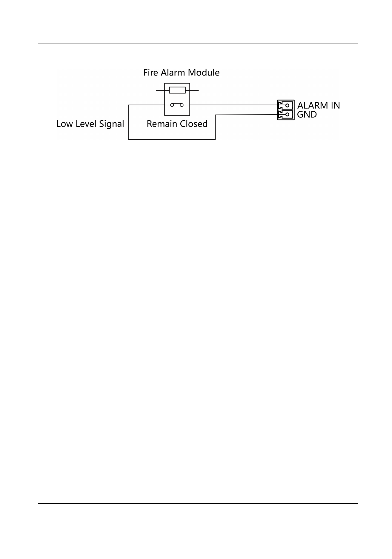
Figure 5-22 Remaining Closed
DS-K3B631TX Series Swing Barrier User Manual
33
Chapter 6 Device Sengs
Aer installaon and wiring completed, the turnsle will study the open and closed posion
automacally.
Aer
the learning, the turnsle is in the normal mode. You can also set the turnsle to study
mode, normal mode, and pair the keyfob, inialize the hardware via the main user extended
interface board (middle/right pedestal).
Study Mode
Study the closed
posion.
Normal Mode
The device will work properly.
Keyfob Pairing
Pair the keyfob and the turnsle.
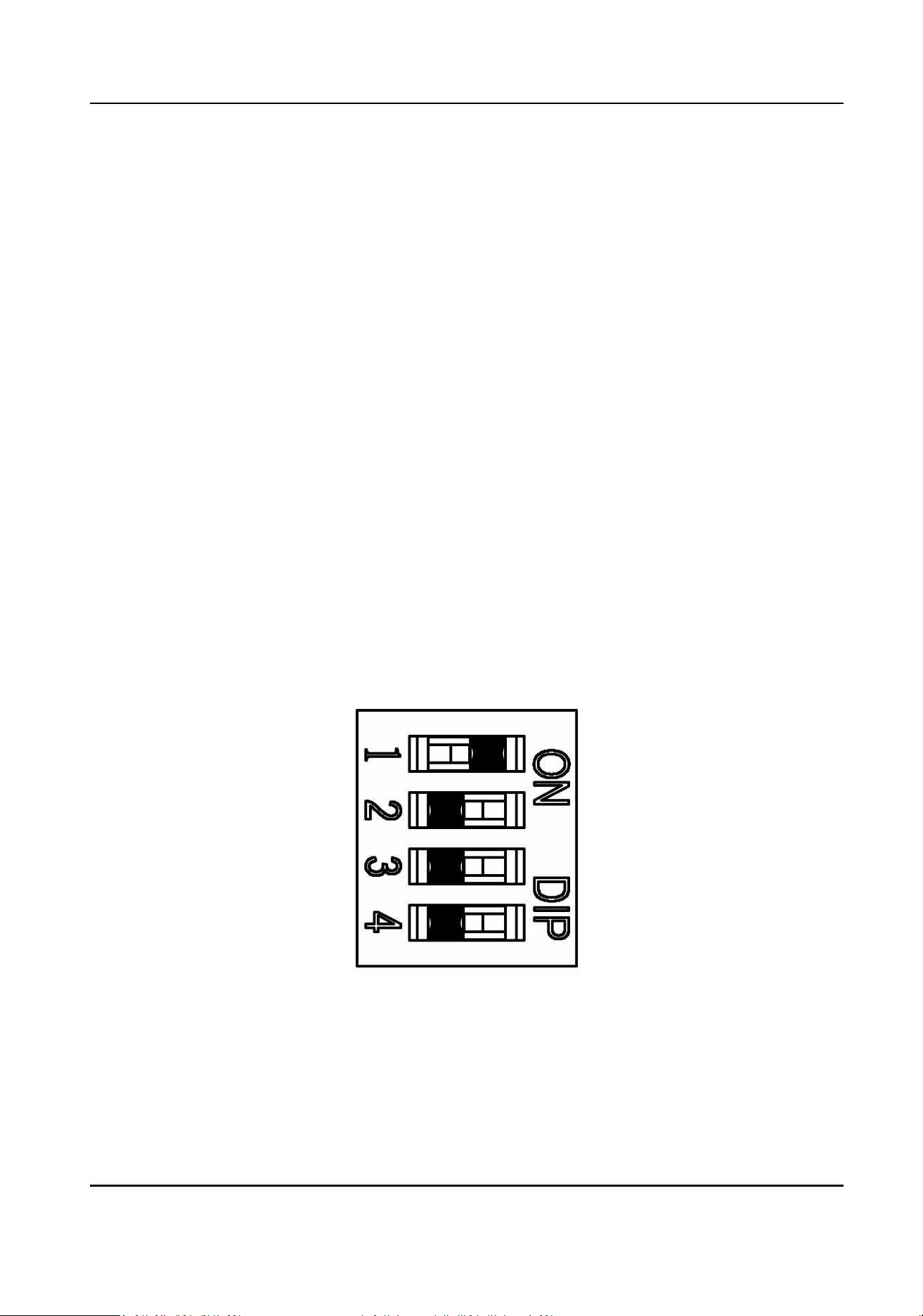
6.1 Set Study Mode
Enter the study mode through DIP switching to set the closed posion of the device barrier.
Steps
1.
Set The No.1 of the 4-digit DIP Switch on the main user extended interface board to ON by
referring the following gure to enter the study mode.
Figure 6-1 Study Mode
2.
Adjust the closed posion of the barrier.
3.
Power on the device.
The device will remember the current
posion (closed posion) automacally.
4.
Power o the device.
DS-K3B631TX Series Swing Barrier User Manual
34
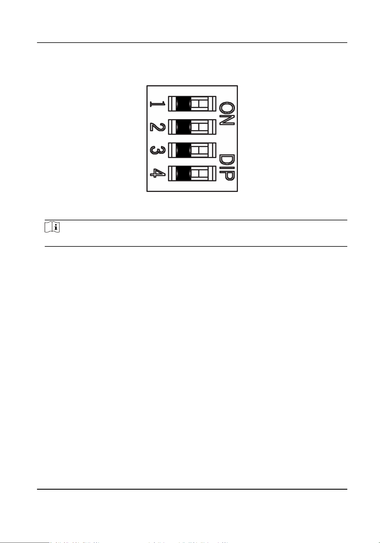
5.
Set the No.1 switches of the 4-digit DIP Switch on the main user extended interface board by
referring to the following gure.
Figure 6-2 Normal Mode
6.
Power on the device again.
Note
For details about the DIP switch value and meaning, see DIP Switch Descripon.
The barrier will open automacally and turns back to the closed posion. At this circumstance,
the device enters the normal mode.
6.2 Pair Keyfob
(Oponal)
Pair the remote control to the device through DIP switch to open/close the barrier remotely.
Before You Start
Ask our technique supports or sales and purchase the keyfob.
Steps
1.
Power o the turnsle.
2.
Set the No.2 switch of the DIP 1 Switch on the access control board to the ON side.
DS-K3B631TX Series Swing Barrier User Manual
35
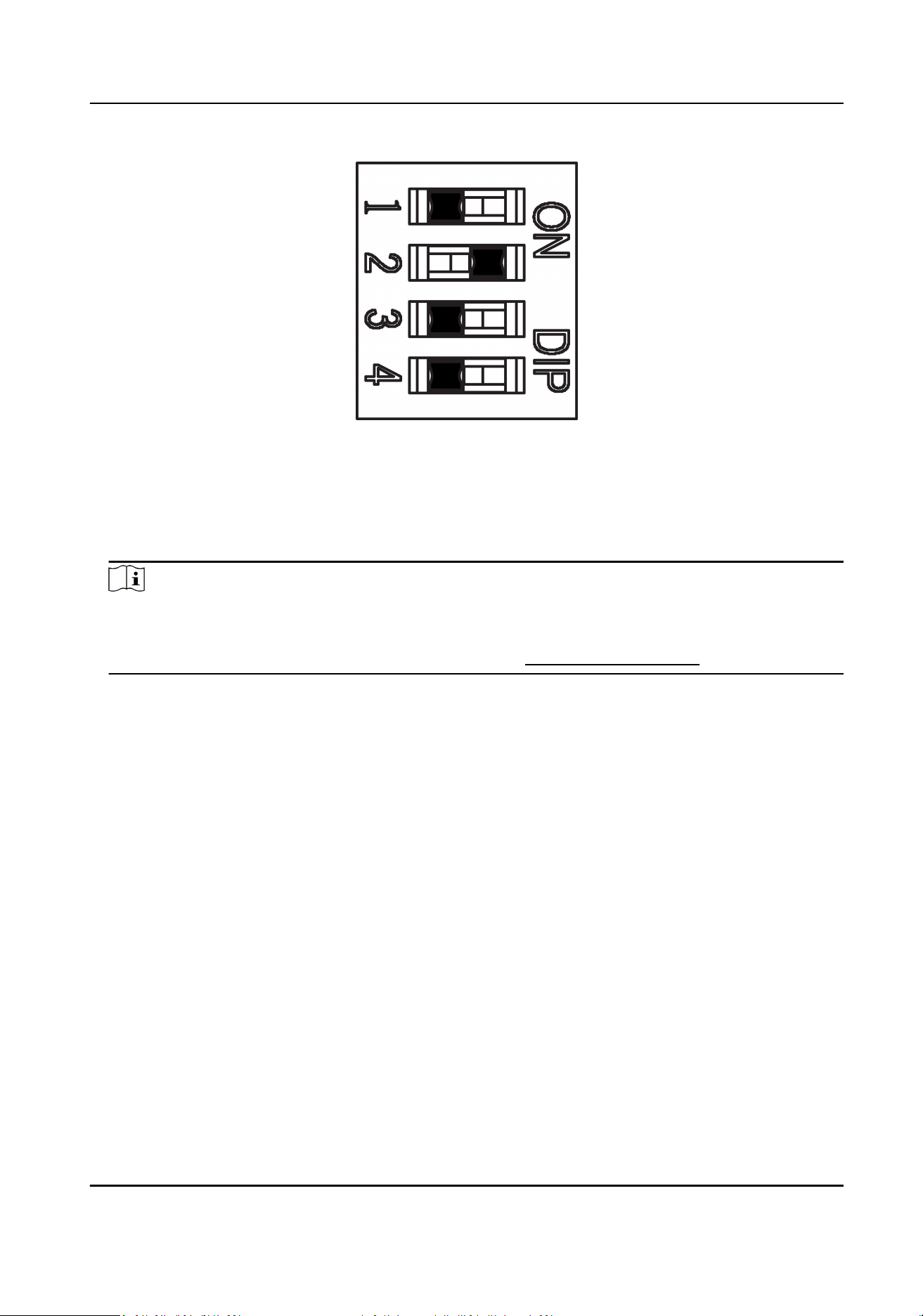
Figure 6-3 Enable Keyfob Paring Mode
3.
Power on the turnsle and it will enter the keyfob pairing mode.
4.
Hold the Close
buon for more than 10 seconds.
The keyfob's indicator of the will ash twice if the pairing is completed.
5.
Set the No.2 switch to the OFF side, and reboot the
turnsle to take eect.
Note
●
Only one turnsle can pair the keyfob. If mulple turnsles are in the pairing mode, the
keyfob will select only one of them to pair.
●
For details about DIP switch value and meaning, see DIP Switch Descripon .
6.
Oponal: Go to System → User → Keyfob User on the remote control page of the client
soware to delete the keyfob.
6.3
Inialize Device
Steps
1.
Hold the
inializaon buon.
DS-K3B631TX Series Swing Barrier User Manual
36
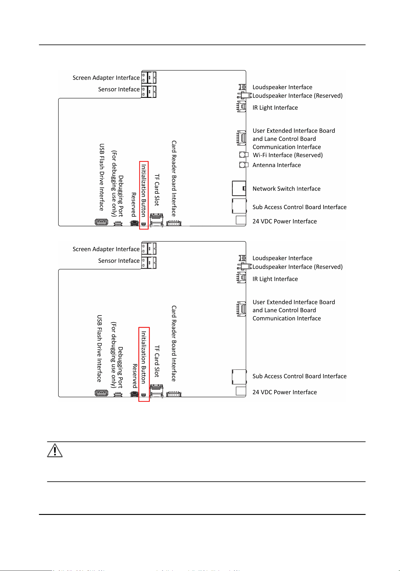
Figure 6-4 Inializaon Buon Posion
2.
Power o and reboot the device. The device buzzer buzzes a long beep.
3.
When the beep stopped, release the
inializaon buon.
Cauon
The inializaon of the device will restore all the parameters to the default seng and all the
device events are deleted.
DS-K3B631TX Series Swing Barrier User Manual
37

Note
Make sure no persons are in the lane when powering on the device.
The inializaon is completed.
DS-K3B631TX Series Swing Barrier User Manual
38

Chapter 7 Acvaon
You should acvate the device before the rst login. Aer powering on the device, the system will
switch to Device
Acvaon page.
Acvaon via the device, SADP tool and the client soware are supported.
The default values of the device are as follows:
●
The default IP address: 192.0.0.64
●
The default port No.: 80
●
The default user name: admin
7.1
Acvate via Device
If the device is not acvated, you can acvate the device aer it is powered on.
On the Acvate Device page, create a password and conrm the password. Tap Acvate and the
device will acvated.
DS-K3B631TX Series Swing Barrier User Manual
39
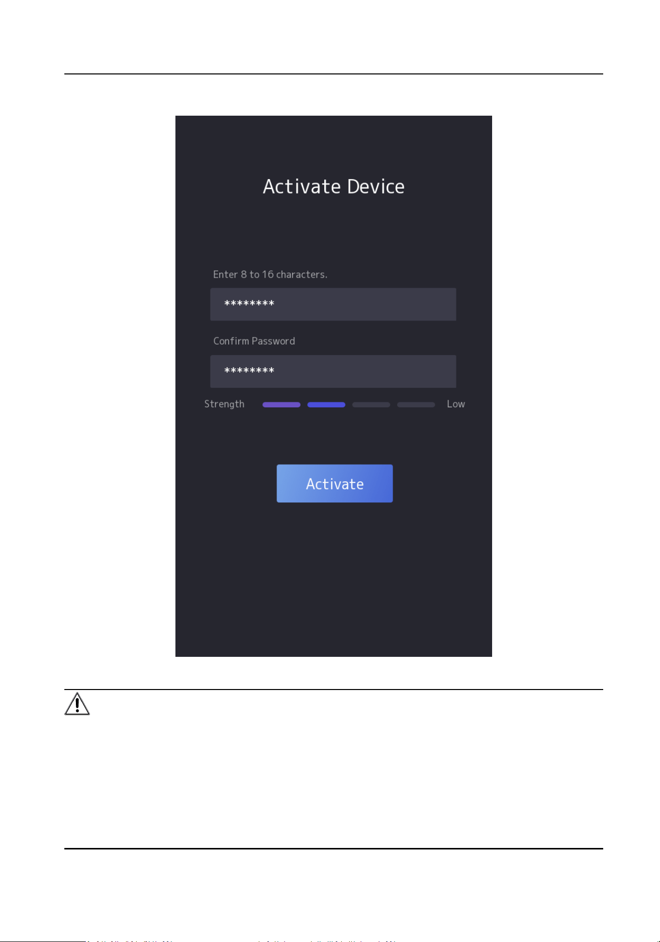
Figure 7-1 Acvaon Page
Cauon
The password strength of the device can be automacally checked. We highly recommend you
change the password of your own choosing (using a minimum of 8 characters, including at least
three kinds of following categories: upper case leers, lower case leers, numbers, and special
DS-K3B631TX Series Swing Barrier User Manual
40
characters) in order to increase the security of your product. And we recommend you change your
password regularly, especially in the high security system, changing the password monthly or
weekly can beer protect your product.
Proper
conguraon of all passwords and other security sengs is the responsibility of the
installer and/or end-user.
Note
Characters containing admin and nimda are not supported to be set as acvaon password.
Aer acvaon, you should select language, set password change type, set applicaon mode, set
network, set
plaorm parameters, set privacy parameters, and set administrator.
7.2
Acvate via Web Browser
You can acvate the device via the web browser.
Steps
1.
Enter the device default IP address (192.0.0.64) in the address bar of the web browser, and press
Enter.
Note
Make sure the device IP address and the computer's should be in the same IP segment.
2.
Create a new password (admin password) and conrm the password.
Cauon
STRONG PASSWORD RECOMMENDED-We highly recommend you create a strong password of
your own choosing (using a minimum of 8 characters, including upper case leers, lower case
leers, numbers, and special characters) in order to increase the security of your product. And
we recommend you reset your password regularly, especially in the high security system,
reseng the password monthly or weekly can beer protect your product.
3.
Click Acvate.
4.
Edit the device IP address. You can edit the IP address via the SADP tool, the device, and the
client
soware.
7.3
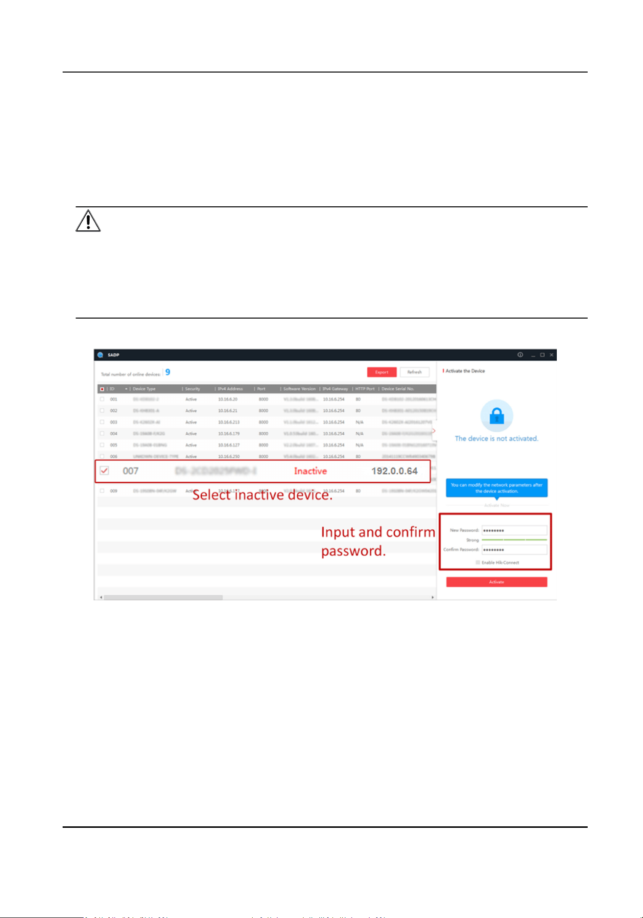
Acvate via SADP
SADP is a tool to detect, acvate and modify the IP address of the device over the LAN.
Before You Start
●
Get the SADP
soware from the supplied disk or the ocial website hp://
www.hikvision.com/en/ , and install the SADP according to the prompts.
●
The device and the PC that runs the SADP tool should be within the same subnet.
DS-K3B631TX Series Swing Barrier User Manual
41
The following steps show how to acvate a device and modify its IP address. For batch acvaon
and IP addresses modicaon, refer to User Manual of SADP for details.
Steps
1.
Run the SADP
soware and search the online devices.
2.
Find and select your device in online device list.
3.
Input new password (admin password) and conrm the password.
Cauon
STRONG PASSWORD RECOMMENDED-We highly recommend you create a strong password of
your own choosing (using a minimum of 8 characters, including upper case leers, lower case
leers, numbers, and special characters) in order to increase the security of your product. And
we recommend you reset your password regularly, especially in the high security system,
reseng the password monthly or weekly can beer protect your product.
4.
Click Acvate to start acvaon.
Status of the device becomes
Acve aer successful acvaon.
5.
Modify IP address of the device.
1) Select the device.
2) Change the device IP address to the same subnet as your computer by either modifying the IP
address manually or checking Enable DHCP.
3) Input the admin password and click Modify to
acvate your IP address modicaon.
DS-K3B631TX Series Swing Barrier User Manual
42
7.4 Acvate Device via iVMS-4200 Client Soware
For some devices, you are required to create the password to acvate them before they can be
added to the iVMS-4200 soware and work properly.
Steps
Note
This funcon should be supported by the device.
1.
Enter the Device Management page.
2.
Click on the right of Device Management and select Device.
3.
Click Online Device to show the online device area.
The searched online devices are displayed in the list.
4.
Check the device status (shown on Security Level column) and select an
inacve device.
5.
Click
Acvate to open the Acvaon dialog.
6.
Create a password in the password eld, and conrm the password.
Cauon
The password strength of the device can be automacally checked. We highly recommend you
change the password of your own choosing (using a minimum of 8 characters, including at least
three kinds of following categories: upper case leers, lower case leers, numbers, and special
characters) in order to increase the security of your product. And we recommend you change
your password regularly, especially in the high security system, changing the password monthly
or weekly can
beer protect your product.
Proper conguraon of all passwords and other security sengs is the responsibility of the
installer and/or end-user.
Note
Characters containing admin and nimda are not supported to be set as acvaon password.
7.
Click OK to acvate the device.
DS-K3B631TX Series Swing Barrier User Manual
43

Chapter 8 Quick Operaon
8.1 Set Device Hotspot
When the device hotspot is enabled, you can connect to the device via hotspot and acvate
remotely.
Click to enable the device hotspot Name and Password.
Note
The default hotspot password is the device serial number.
Click Next and scan the QR code to log in to mobile web.
DS-K3B631TX Series Swing Barrier User Manual
44
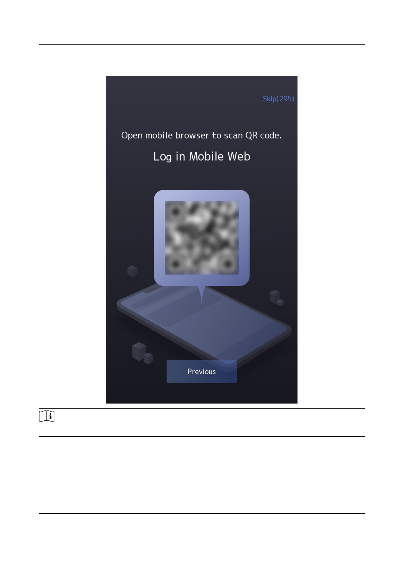
Note
You need to enter the hotspot password for mobile web log-in.
8.2 Acvate via Device
If the device is not acvated, you can acvate the device aer it is powered on.
DS-K3B631TX Series Swing Barrier User Manual
45
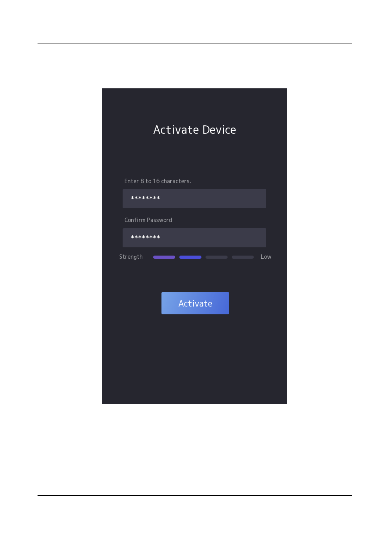
On the Acvate Device page, create a password and conrm the password. Tap Acvate and the
device will acvated.
Figure 8-1 Acvaon Page
DS-K3B631TX Series Swing Barrier User Manual
46
Cauon
The password strength of the device can be automacally checked. We highly recommend you
change the password of your own choosing (using a minimum of 8 characters, including at least
three kinds of following categories: upper case leers, lower case leers, numbers, and special
characters) in order to increase the security of your product. And we recommend you change your
password regularly, especially in the high security system, changing the password monthly or
weekly can
beer protect your product.
Proper conguraon of all passwords and other security sengs is the responsibility of the
installer and/or end-user.
Note
Characters containing admin and nimda are not supported to be set as acvaon password.
Aer acvaon, you should select language, set password change type, set applicaon mode, set
network, set plaorm parameters, set privacy parameters, and set administrator.
8.3 Set
Applicaon Mode
Aer acvang the device, you should select an applicaon mode for beer device applicaon.
Steps
1.
On the Welcome page, select Indoor or Others from the drop-down list.
DS-K3B631TX Series Swing Barrier User Manual
47
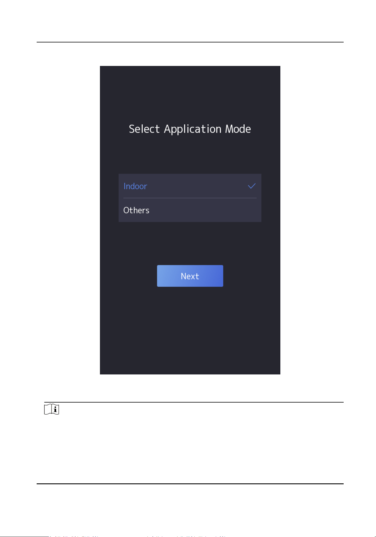
Figure 8-2 Welcome Page
2.
Tap OK to save.
Note
●
You can also change the sengs in System Sengs.
●
If you install the device indoors near the window or the face recognion funcon is not
working well, select Others.
DS-K3B631TX Series Swing Barrier User Manual
48

●
If you do not congure the applicaon mode and tap Next, the system will select Indoor by
default.
●
If you acvate the device via other tools remotely, the system will select Indoor as the
applicaon mode by default.
8.4 Set Network Parameters
Aer
acvaon and select applicaon mode, you can set the network for the device
Steps
1.
Set the wired network parameters.
-
If enable DHCP, the system will assign the IP address and other parameters automacally.
-
If disable DHCP, you should set the IP address, the subnet mask, and the gateway.
Note
●
Make sure the device has connected to a network.
●
When the IP address, the subnet mask, and the gateway are assigned automacally, the DHCP
will be disabled.
DS-K3B631TX Series Swing Barrier User Manual
49
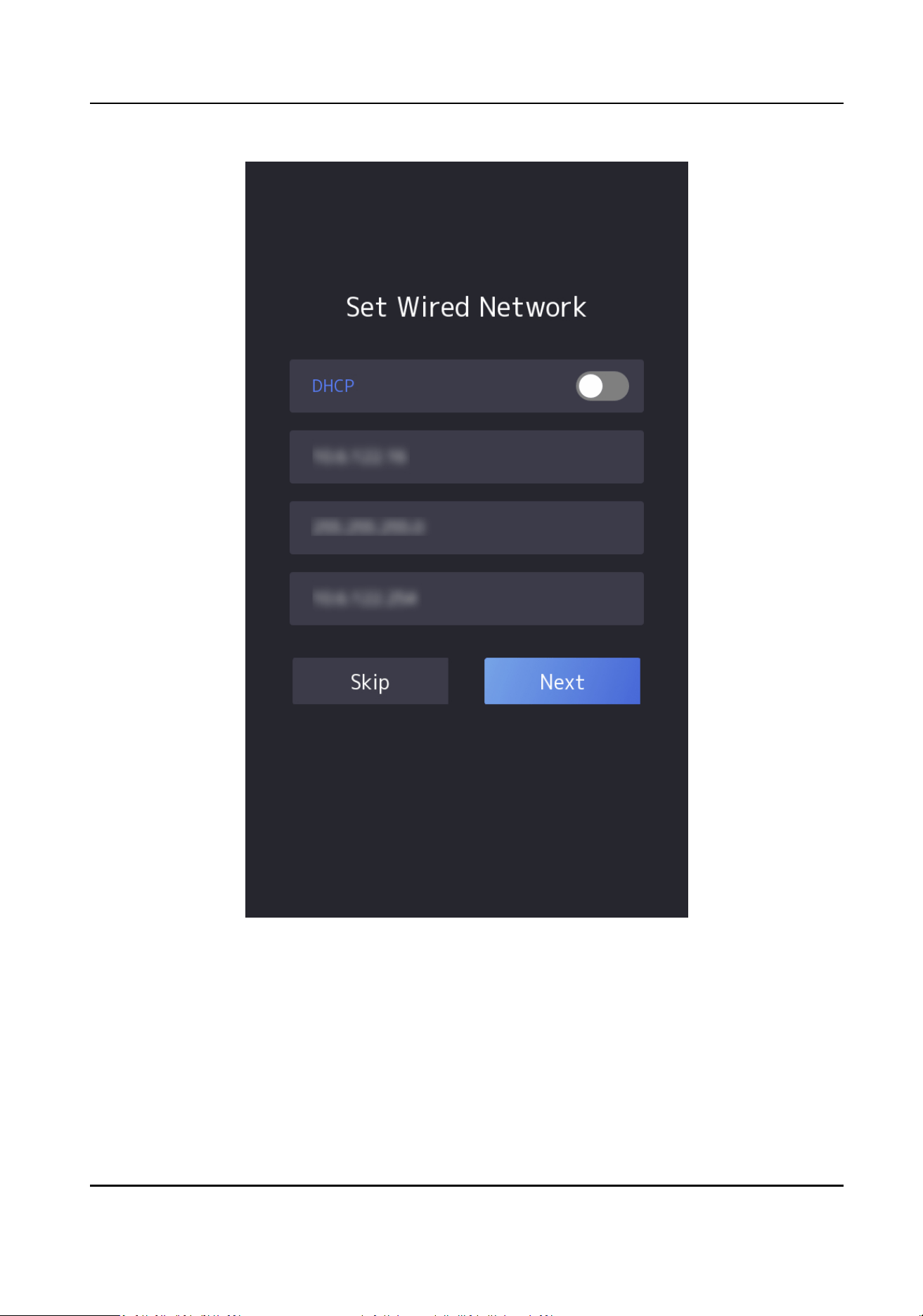
Figure 8-3 Wired Network
2.
Tap Next.
3.
Oponal: Tap Skip to skip network sengs.
8.5 Privacy
Sengs
Set the privacy parameters, including the picture uploading and storage.
DS-K3B631TX Series Swing Barrier User Manual
50

Select parameters according to your actual needs.
Upload Pic. Aer Linked Capture (Upload Picture Aer Linked Capture)
Upload the pictures captured by linked camera to the plaorm automacally.
Save Pic. Aer Linked Capture (Save Pictures Aer Linked Capture)
If you enable this funcon, you can save the picture captured by linked camera to the device.
Tap Next to complete the sengs.
8.6 Keyfob Sengs
Set the keyfob working mode and add keyfob.
DS-K3B631TX Series Swing Barrier User Manual
51
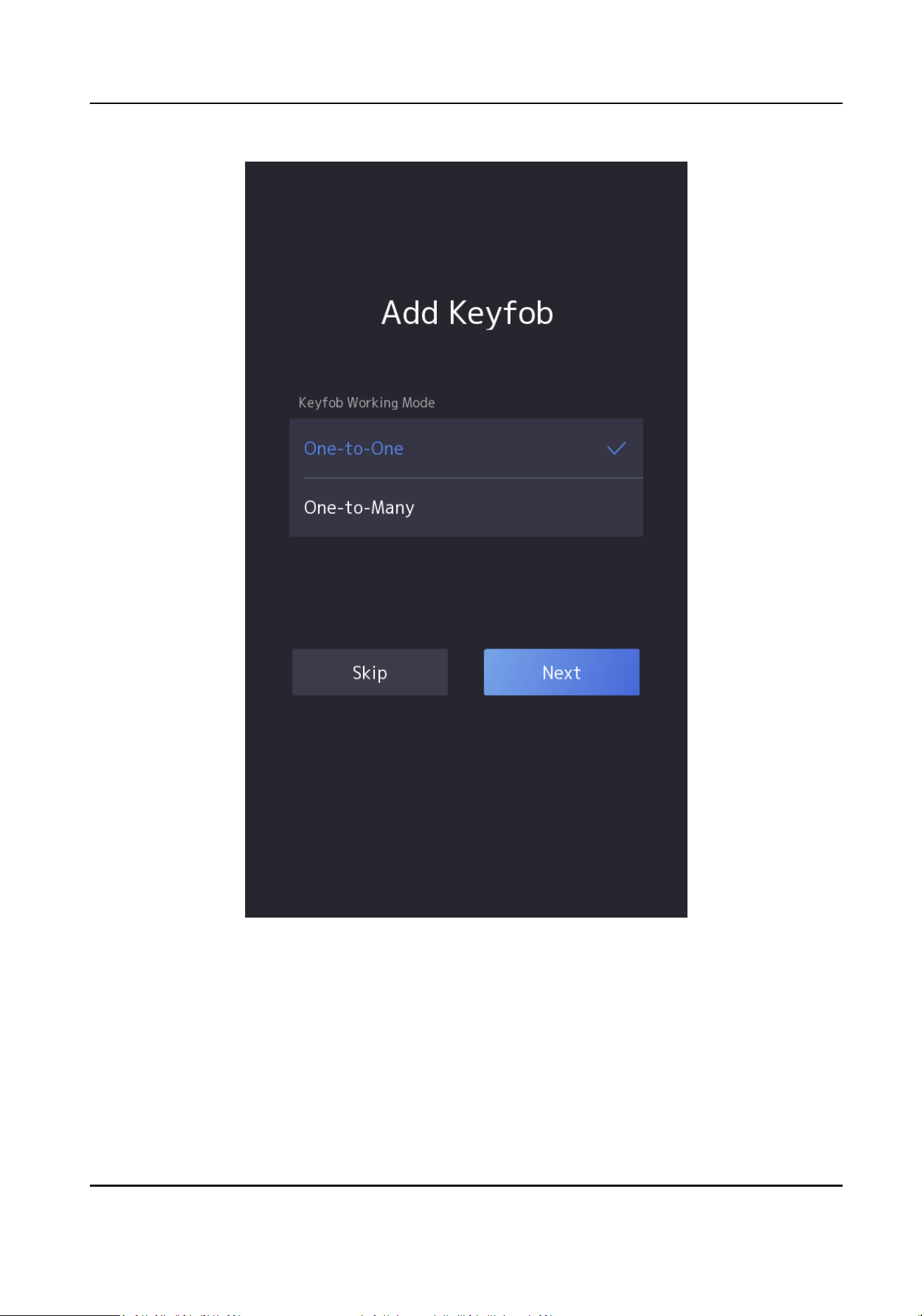
Figure 8-4 Keyfob Sengs
Set Working Mode as One-to-One or One-to-Many. Tap Next.
Set keyfob name and serial No..
Tap Skip or Next.
DS-K3B631TX Series Swing Barrier User Manual
52

8.7 Set Administrator
Aer device acvaon, you can add an administrator to manage the device parameters.
Before You Start
Acvate the device and select an applicaon mode.
Steps
1.
Oponal: Tap Skip to skip adding administrator if required.
2.
Enter the administrator's name
(oponal) and tap Next.
DS-K3B631TX Series Swing Barrier User Manual
53
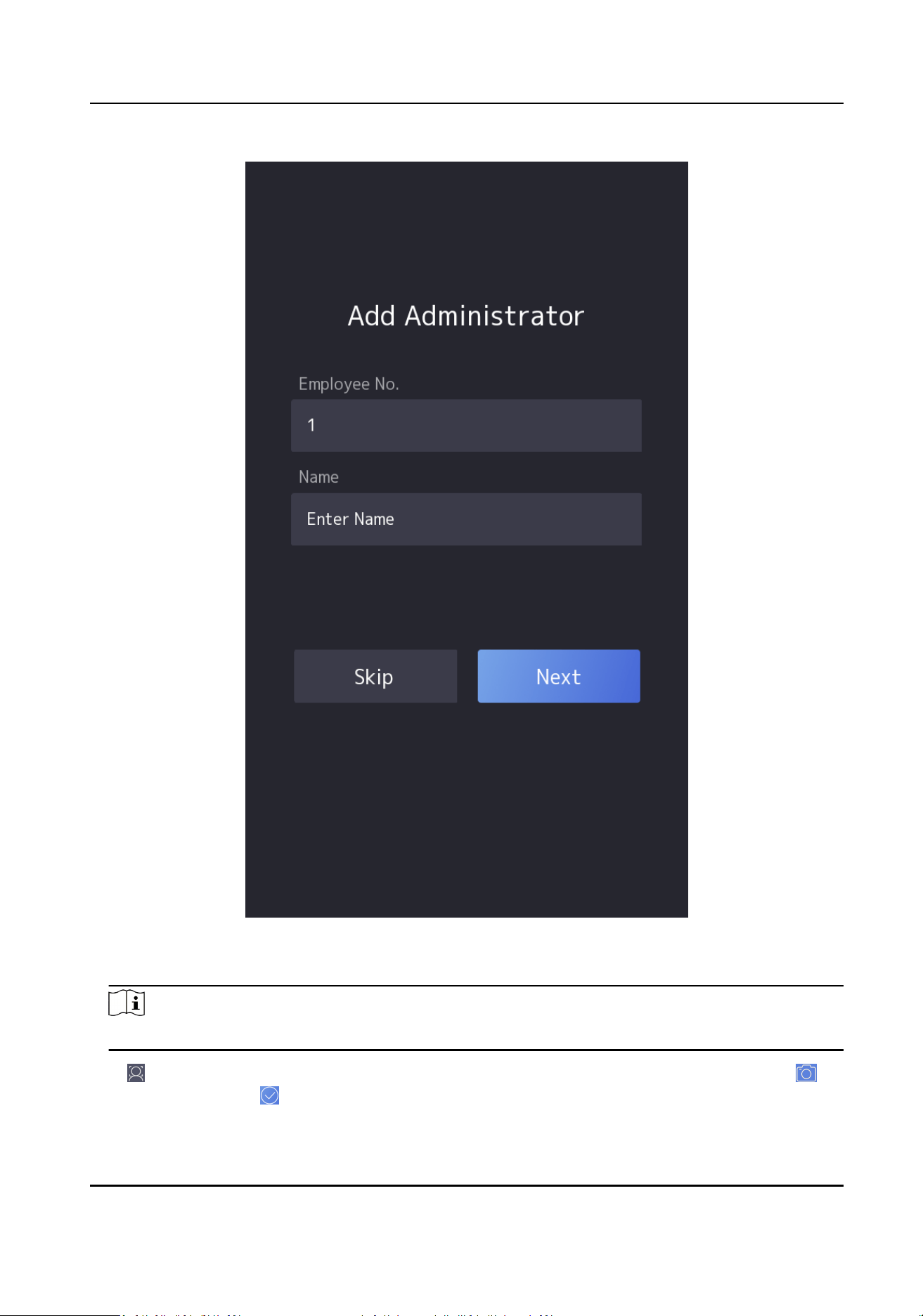
Figure 8-5 Add Administrator Page
3.
Select a credenal to add.
Note
Up to one credenal should be added.
-
: Face forward at the camera. Make sure the face is in the face recognion area. Click to
capture and click to conrm.
DS-K3B631TX Series Swing Barrier User Manual
54

-
-
: Enter the card No. Click OK.
4.
Click OK.
You will enter the
authencaon page.
Status Icon
Descripon
/
Device is armed/not armed.
/ /
The device wired network is connected/not connected/connecng failed.
3G/4G is enabled.
DS-K3B631TX Series Swing Barrier User Manual
55

Chapter 9 Quick Operaon via Web Browser
9.1 Time Sengs
Click in the top right of the web page to enter the wizard page.
Time Zone
Select the device located me zone from the drop-down list.
Time Sync.
NTP
You should set the NTP server's IP address, port No., and interval.
Manual
By default, the device me should be synchronized manually. You can set the device me
manually or check Sync. with Computer Time to synchronize the device me with the
computer's me.
Server Address/NTP Port/Interval
You can set the server address, NTP port, and interval.
DST
You can view the DST start me, end me and bias me.
Click Next to save the sengs and go to the next parameter. Or click Skip to skip me sengs.
9.2 Environment
Sengs
Aer acvang the device, you should select an applicaon mode for beer device applicaon.
Steps
1.
Click in the top right of the web page to enter the wizard page. Aer seng me, you can
click Next to enter the Environment
Sengs page.
2.
Select Indoor or Other.
Note
●
If you install the device indoors near the window or the face recognion funcon is not
working well, select Others.
●
If you do not congure the applicaon mode and tap Next, the system will select Indoor by
default.
Click Next to save the sengs and go to the next parameter. Or click Skip to skip environment
sengs.
DS-K3B631TX Series Swing Barrier User Manual
56

9.3 Privacy Sengs
Set the picture uploading and storage parameters.
Click in the top right of the web page to enter the wizard page. Aer seng me and
environment, you can click Next to enter the Privacy Sengs page.
Picture Uploading and Storage
Save Picture When Auth.
Save picture when authencang automacally.
Upload Picture When Auth.
Upload the pictures when authencang to the plaorm automacally.
Save Registered Picture
The registered face picture will be saved to the system if you enable the funcon.
Upload Picture Aer Linked Capture
Upload the pictures captured by linked camera to the plaorm automacally.
Save Pictures Aer Linked Capture
If you enable this funcon, you can save the picture captured by linked camera to the device.
Click Next to save the sengs and go to the next parameter. Or click Skip to skip environment
sengs.
9.4 Administrator
Sengs
Steps
1.
Click
in the top right of the web page to enter the wizard page. Aer seng previous
parameters, you can click Next to enter the Administrator Sengs page. Or you can click Skip to
enter the Administrator
Sengs page directly.
2.
Enter the employee ID and name of the administrator.
3.
Select a
credenal to add.
1) Click Add Card to enter the Card No. and select the property of the card.
Note
Up to 50 cards can be supported.
4.
Click Complete to complete the sengs.
DS-K3B631TX Series Swing Barrier User Manual
57

Chapter 10 Operaon via Web Browser
10.1 Login
You can login via the web browser or the remote conguraon of the client soware.
Note
Make sure the device is acvated. For detailed informaon about acvaon, see Acvaon .
Login via Web Browser
Enter the device IP address in the address bar of the web browser and press Enter to enter the
login page.
Enter the device user name and the password. Click Login.
Login via Remote
Conguraon of Client Soware
Download and open the client soware. Aer adding the device, click to enter the Conguraon
page.
10.2 Overview
You can view the device component status, real-me event, person informaon, network status,
basic
informaon, and device capacity. You can also control the barrier remotely.
Funcon Descripons:
Device Component Status
You can check if the device is working properly. Click View More to view the detailed
component status.
Remote Control
/ / /
The door is opened/closed/remaining open/remaining closed.
Real-Time Event
You can view the event Employee ID, Name, Card No., Event Type, Time, and Operaon. You can
also click View More to enter the search condions, including the event type, employee ID, the
name, the card No., the start
me, and the end me, and click Search. The results will be
displayed on the right panel.
Person Informaon
You can view the added and not added informaon of person and card.
Network Status
DS-K3B631TX Series Swing Barrier User Manual
58

You can view the network connecon status.
Basic Informaon
You can view the model, serial No. and rmware version.
Device Capacity
You can view the person, face, card and event capacity.
10.3 Person Management
Click Add to add the person's informaon, including the basic informaon, cercate, and
authencaon sengs.
Add Basic
Informaon
Click Person Management → Add to enter the Add Person page.
Add the person's basic
informaon, including the employee ID, the person's name, etc.
Click Save to save the sengs.
Set Permission Time
Click Person Management → Add to enter the Add Person page.
Enable Long-Term Eecve User, or set Start Time and End Time and the person can only has the
permission within the
congured me period according to your actual needs.
Click Save to save the sengs.
Authencaon
Sengs
Click Person Management → Add to enter the Add Person page.
Set the
authencaon type.
Click Save to save the sengs.
Add Card
Click Person Management → Add to enter the Add Person page.
Click Add Card, enter the Card No. and select the Property, and click Save to add the card.
Click Save to save the
sengs.
Import/Export Person Data
Export Person Data
You can export added person data for back-up or imporng to other devices.
Click Export Person Data, set an
encrypon password and conrm it. Click OK.
Note
●
The person data will be downloaded to your PC.
●
The password you set will be required for imporng the data le.
DS-K3B631TX Series Swing Barrier User Manual
59

Imporng Person Data
Click Imporng Person Data and select the le. Click Import.
Enter the
encrypon password to import and synchronize the person data to devices.
Note
●
Please ensure the name of the imported le is "UserDataFile".
10.4 Search Event
Click Event Search to enter the Search page.
Select event types, major type and sub type. Enter the search
condions, including the employee
ID, the name, the card No., the start me, and the end me, and click Search.
The results will be displayed on the right panel.
10.5 Device Management
You can manage the linked device on the page.
Steps
1.
Click Device Management to enter the
sengs page.
2.
You can view the Device Type, Card Reader ID, Acvaon Status, Registraon Status, IP
Address, Gateway Address, Mask Address, Communicaon Port, Serial No., MAC and PoE Port.
3.
Click
to view the device network sengs.
4.
Click Refresh to get the device informaon.
5.
Oponal: Other operaons.
View Device
Informaon Click to edit device informaon.
Reboot Device Click to reboot the selected device.
10.6 Conguraon
10.6.1 Set Local Parameters
Set the live view parameters, picture and clip sengs.
Set Live View Parameters
Click Conguraon → Local to enter the Local page. Congure the stream type, the play
performance, auto start Live View and click Save.
DS-K3B631TX Series Swing Barrier User Manual
60

Record File Sengs
Click Conguraon → Local to enter the Local page. Select a record le size and select a saving
path from your local computer and click Save.
You can also click Open to open the
le folder to view details.
Picture and Clip Sengs
Click Conguraon → Local to enter the Local page. Select image format, saving path and click
Save.
You can also click Open to open the le folder to view details.
10.6.2 View Device Informaon
View the device name, device No., language, model, serial No., version, number of channels, IO
input, IO output, lock, alarm input, alarm output, and device capacity, etc.
Click
Conguraon → System → System Sengs → Basic Informaon to enter the conguraon
page.
You can view the language, model, serial No., version, IO input, IO output, local RS-485, alarm input
and alarm output number.
You can change Device Name and click Save.
Click Upgrade to upgrade the
rmware version.
You can view the device capacity, including person, card, face and event.
10.6.3 Set Time
Set the device's me zone, synchronizaon mode, server address, NTP port, and interval.
Click Conguraon → System → System Sengs → Time Sengs .
Click Save to save the
sengs aer the conguraon.
Time Zone
Select the device located me zone from the drop-down list.
Time Sync.
Manual
By default, the device
me should be synchronized manually. You can set the device me
manually or check Sync. with Computer Time to synchronize the device me with the
computer's me.
Server IP Address/NTP Port/Interval
You can set the server IP address, NTP port, and interval.
DS-K3B631TX Series Swing Barrier User Manual
61

10.6.4 Set DST
Steps
1.
Click
Conguraon → System → System Sengs → Time Sengs .
2.
Enable DST.
3.
Set the DST start me, end me and bias me.
4.
Click Save to save the sengs.
10.6.5 Change Administrator's Password
Steps
1.
Enter the password change page.
-
Click
Conguraon → System → User Management and click .
-
Click admin → Modify Password at the upper right corner of the page.
2.
Enter the old password and create a new password.
3.
Conrm the new password.
4.
Click Save.
Cauon
The password strength of the device can be automacally checked. We highly recommend you
change the password of your own choosing (using a minimum of 8 characters, including at least
three kinds of following categories: upper case leers, lower case leers, numbers, and special
characters) in order to increase the security of your product. And we recommend you change
your password regularly, especially in the high security system, changing the password monthly
or weekly can
beer protect your product.
Proper conguraon of all passwords and other security sengs is the responsibility of the
installer and/or end-user.
10.6.6 Online Users
The informaon of users logging into the device is shown.
Go to Conguraon → System → User Management → Online Users to view the list of online
users.
10.6.7 View Device Arming/Disarming
Informaon
View device arming type and arming IP address.
Click
Conguraon → System → User Management → Arming/Disarming Informaon .
You can view the device arming/disarming informaon. Click Refresh to refresh the page.
DS-K3B631TX Series Swing Barrier User Manual
62

10.6.8 Network Sengs
Set Basic Network Parameters
Click Conguraon → Network → Network Sengs → TCP/IP .
You can view the mac address and MTU.
Set the parameters and click Save to save the sengs.
NIC Type
Select a NIC type from the drop-down list. By default, it is Self-Adapve.
DHCP
If you disable DHCP, you should manually set the IPv4 address, IPv4 subnet mask, IPv4 default
gateway, preferred DNS server, and alternate DNS server.
If you enable DHCP, the system will automacally allocate the IPv4 address, IPv4 subnet mask,
the IPv4 default gateway preferred DNS server and alternate DNS server.
DNS Server
Set the preferred DNS server and the Alternate DNS server according to your actual need.
Device Hotspot
Set the device hotspot.
Click
Conguraon → Network → Network Sengs → Device Hotspot .
Click to Enable Device Hotspot. Set hotspot Name and Password.
Click Save.
Set Port Parameters
Set the HTTP, HTTPS, HTTP Listening and RTSP parameters.
Click
Conguraon → Network → Network Service → HTTP(S) .
DS-K3B631TX Series Swing Barrier User Manual
63
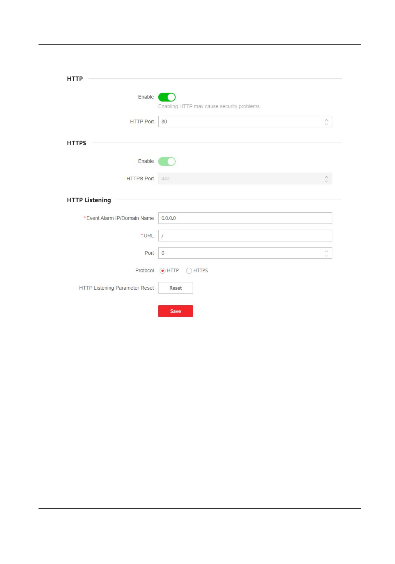
Figure 10-1 Set Port
HTTP
It refers to the port through which the browser accesses the device. For example, when the
HTTP Port is modied to 81, you need to enter hp://192.0.0.65:81 in the browser for login.
HTTPS
Set the HTTPS for accessing the browser.
Cercate is required when accessing.
HTTP Listening
The device can send alarm informaon to the event alarm IP address or domain name via HTTP
protocol/HTTPS protocol. Edit the event alarm IP address or domain name, URL, port, and
protocol.
DS-K3B631TX Series Swing Barrier User Manual
64
Note
The event alarm IP address or domain name should support the HTTP protocol/HTTPS protocol
to receive the alarm informaon.
You can also click Reset to reset the HTTP listening parameters.
Click
Conguraon → Network → Network Service → RTSP .
RTSP
It refers to the port of real-me streaming protocol.
10.6.9 Set Video and Audio Parameters
Set the image quality and resoluon.
Set Video Parameters
Click Conguraon → Video/Audio → Video .
Choose a video channel and set the camera name, stream type,
resoluon and the video encoding.
Click Save to save the sengs aer the conguraon.
Note
Video type, bitrate type, video quality, Max. bitrate, and I Frame Interval are read-only.
Set Audio Parameters
Click Conguraon → Video/Audio → Audio .
Choose an audio channel and drag the block or enter value to adjust the device output volume.
Click to enable Voice Prompt.
Click Save to save the
sengs aer the conguraon.
Note
The funcons vary according to dierent models. Refers to the actual device for details.
10.6.10 Set Image Parameters
You can adjust the image parameters.
Steps
1.
Click Conguraon → Image .
2.
Select channel.
3.
Congure the parameters to adjust the image.
Image Adjustment
DS-K3B631TX Series Swing Barrier User Manual
65

Drag the block or enter the value to adjust the live video's brightness, contrast, saturaon,
and sharpness.
LED Light
Set the light type from the drop down list and select the mode to enable or disable it.
If you select Open, you can set the light brightness.
If you select Disable, the funcon will be disabled.
Backlight
Enable or disable WDR.
When there are both very bright and very dark areas simultaneously in the view, WDR
balances the brightness level of the whole image and provide clear images with details.
Video Adjust(Video Standard)
Set the video frame rate when performing live view remotely.
Aer changing the standard,
you should reboot the device to take eect.
PAL
25 frames per second. Suitable for mainland China, Hong Kong (China), the Middle East
countries, Europe countries, etc.
NTSC
30 frames per second. Suitable for the USA, Canada, Japan, Taiwan (China), Korea, the
Philippines, etc.
Beauty
Click to enable Beauty and set whiten and smooth value for the face appeared on the device
live view page.
4.
Click Restore Default
Sengs to restore the parameters to the default sengs.
10.6.11 Event Linkage
Set linked acons for events.
Steps
1.
Click Conguraon → Event → Event Detecon → Linkage Sengs to enter the page.
2.
Set event source.
-
If you choose Linkage Type as Event Linkage, you need to select event types from the drop-
down list.
-
If you choose Linkage Type as Card Linkage, you need to enter the card No. and select the
card reader.
-
If you choose Linkage Type as Employee ID Linkage, you need to enter the employee ID and
select the card reader.
3.
Set linkage acon.
Linked Buzzer
DS-K3B631TX Series Swing Barrier User Manual
66

Enable Linked Buzzer and select Start Buzzing or Stop Buzzing for the target event.
Linked Door
Enable Linked Door, check Door 1 or Door 2, and set the door status for the target event.
Linked Alarm Output
Enable Linked Alarm Output, check Alarm Output 1 or Alarm Output 2, and set the alarm
output status for the target event.
Linked Audio Prompt
Enable Linked Audio Prompt and select the play mode.
●
If you choose TTS, you need to set language and enter the prompt content.
●
If you choose Audio File, you need to select an available audio
le from the drop-down list
or click General Linkage
Sengs to add a new audio le.
Linked Capture
Enable Linked Capture and select entrance or exit to capture for the target event.
10.6.12 Access Control
Sengs
Set Authencaon Parameters
Click Conguraon → Access Control → Authencaon Sengs .
Note
The funcons vary according to dierent models. Refers to the actual device for details.
Click Save to save the sengs aer the conguraon.
Terminal
Choose Entrance or Exit for sengs.
Enable Authencaon Device
Enable the authencaon funcon.
Authencaon
Select an authencaon mode according to your actual needs from the drop-down list.
Connuous Face Recognion Interval
You can set the interval between 2 connuous recognion of a same person during the
authencaon. In the congured interval, Person A can only recognized once. If another person
(Person B) has recognized during the interval, Person A can recognized again.
Note
The recognion internal value ranges from 1 to 10.
DS-K3B631TX Series Swing Barrier User Manual
67

Authencaon Interval
You can set the authencaon interval of the same person when authencang. The same
person can only
authencate once in the congured interval. A second authencaon will be
failed.
Alarm of Max. Failed Aempts
Enable to report alarm when the card reading aempts reach the set value.
Max. Authencaon Failed Aempts
Enable to report alarm when the card reading aempts reach the set value.
Communicaon with Controller Every
When the access control device cannot connect with the card reader for longer than the set
me, the card reader will turn oine automacally.
Note
The authencaon interval value ranges from 2 s to 255 s.
Set Door Parameters
Click Conguraon → Access Control → Door Parameters .
Click Save to save the sengs aer the conguraon.
Door No.
Select Entrance or Exit for sengs.
Door Name
You can create a name for the door.
Open Duraon
Set the door unlocking duraon. If the door is not opened for the set me, the door will be
locked.
Note
The open duraon ranges from 5 s to 60 s.
Exit Buon Type
You can set the exit buon as Remain Open or Remain Closed according to your actual needs.
By default, it is Remain Open.
Door Remain Open Duraon with First Person
Set the door open duraon when rst person is in. Aer the rst person is authorized, it allows
mulple persons access the door or other authencaon acons.
DS-K3B631TX Series Swing Barrier User Manual
68
Note
The duraon ranges from 1 s to 1440 s.
Serial Port Sengs
Set serial port parameters.
Steps
1.
Click Conguraon → Access Control → Serial Port Conguraon .
2.
Select the serial port posion.
3.
Select a serial port No., and the corresponding serial port type will display automacally.
4.
Set Baud Rate, Data Bit, Stop Bit and Parity.
5.
Set the Peripheral Type as Card Reader, Card Receiver, QR Code Scanner, or Disable.
6.
You can view the connected device model and peripheral
soware version.
7.
Click Save.
Set Wiegand Parameters
You can set the Wiegand transmission direcon.
Steps
Note
Some device models do not support this funcon. Refer to the actual products when conguraon.
1.
Click Conguraon → Access Control → Wiegand Sengs .
2.
Select Entrance or Exit.
3.
Enable Wiegand
funcon.
4.
The wiegand transmission direcon is set Input by default.
Note
Input: the device can connect a Wiegand card reader.
5.
Select Wiegand Mode.
6.
Click Save to save the
sengs.
Note
If you change the peripheral, and aer you save the device parameters, the device will reboot
automacally.
DS-K3B631TX Series Swing Barrier User Manual
69
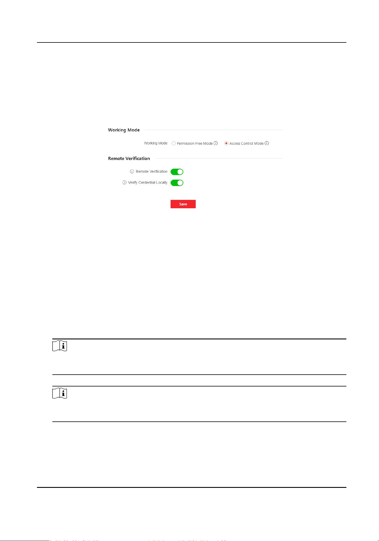
Set Terminal Parameters
Set the working mode and remote vericaon.
Steps
1.
Click Conguraon → Access Control → Terminal Parameters to enter the page.
Figure 10-2 Terminal Parameters
2.
Set the device working mode.
Permission Free Mode
The device will not verify the person's permission, but only the person's validity period. If the
person is in the validity period, the barrier will open.
You can enable Verify
Credenal Locally. Aer enabling the funcon, the device will only
verify the person's permission without the schedule template, etc.
Access Control Mode
The device works normally and will verify the person's permission to open the barrier.
3.
Set remote
vericaon.
1) Enable Remote Vericaon.
Note
The device will upload the person's authencaon informaon to the plaorm. The plaorm
will judge to open the barrier or not.
2) Oponal: Enable Verify Credenal Locally.
Note
Aer enabling the funcon, the device will only verify the person's permission without the
schedule template, etc.
4.
Click Save to complete terminal parameter sengs.
DS-K3B631TX Series Swing Barrier User Manual
70
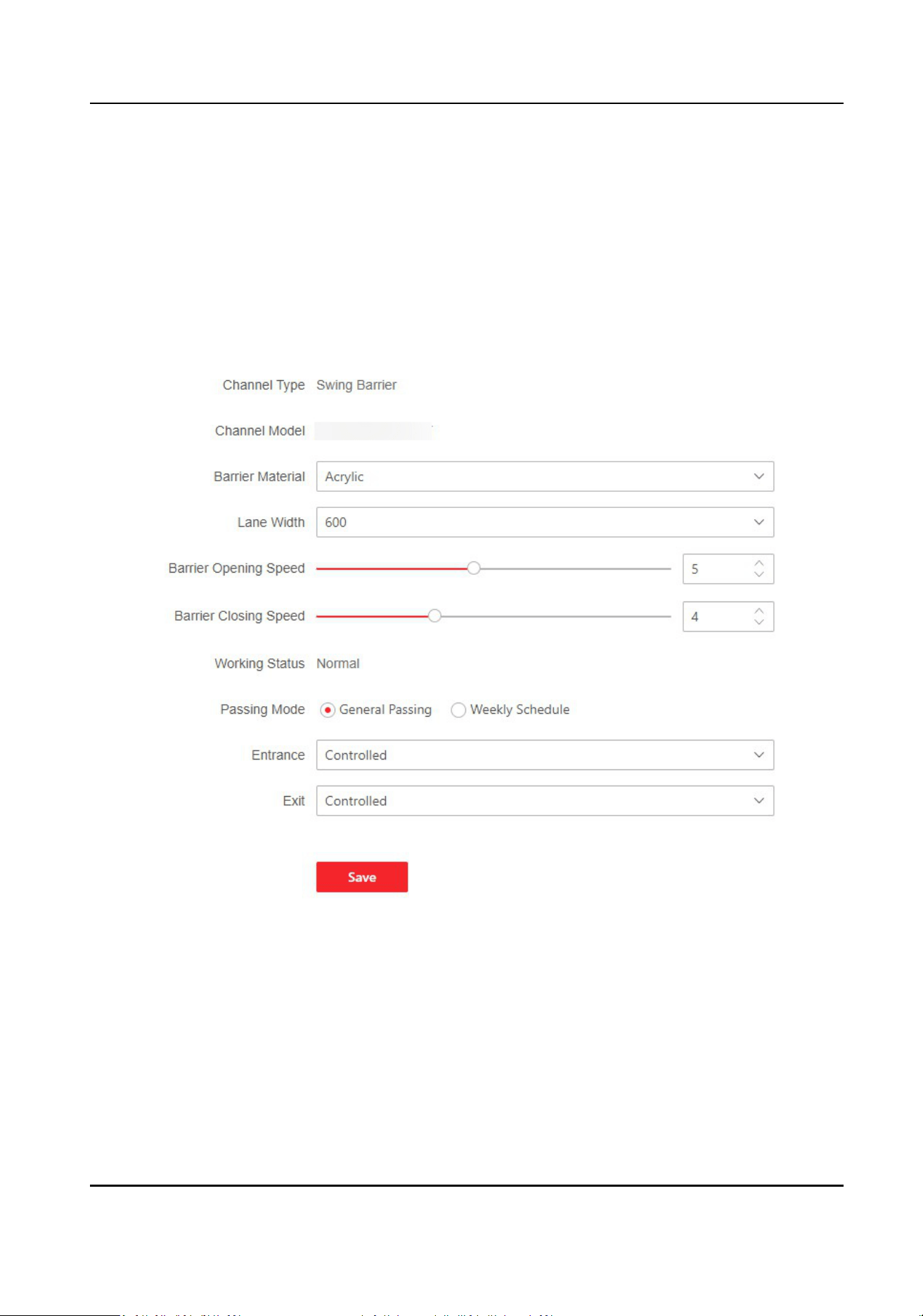
10.6.13 Turnsle
Basic Parameters
Set turnsle basic parameters.
Steps
1.
Click Conguraon → Turnsle Conguraon → Basic Sengs to enter the page.
Figure 10-3 Basic Sengs
2.
View the Channel Type and Channel Model and Working Status.
3.
Set Barrier Material, Lane Width, Barrier Opening Speed and Barrier Closing Speed.
4.
Set the passing mode.
-
If you choose General Passing, you can select the barrier status for the entrance and exit from
the drop-down list.
DS-K3B631TX Series Swing Barrier User Manual
71
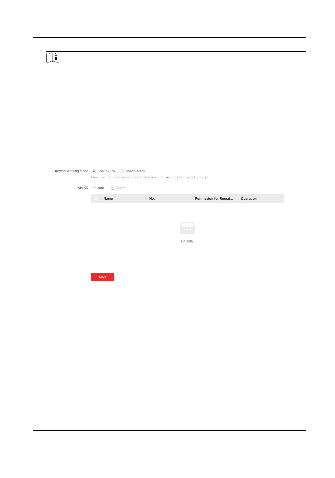
Note
If you set barrier-free mode, the barrier remains open and will close when authencaon
fails.
-
If you choose Weekly Schedule, you can set a weekly schedule for entrance and exit barriers.
5.
Click Save.
keyfob
Set keyfob parameters.
Steps
1.
Click Conguraon → Turnsle Conguraon → Keyfob Conguraon to enter the page.
Figure 10-4 keyfob
2.
Set Working Mode as One-to-One or One-to-Many.
3.
Add keyfob.
1) Click Add and the keyfob adding window will pop up.
2) Enter the Name and Serial No..
3) Check to enable Permission for Remaining Open at your actual needs.
4) Click Add to add the keyfob.
4.
Oponal: Select a keyfob and click Delete to delete the keyfob.
5.
Click Save.
IR Detector
Set IR detector.
DS-K3B631TX Series Swing Barrier User Manual
72
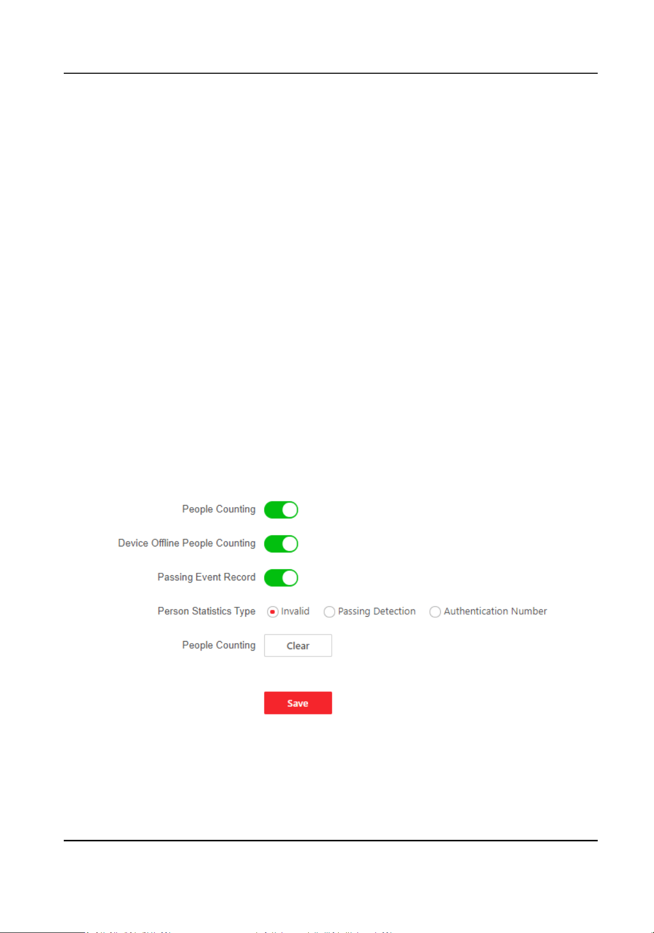
Steps
1.
Click Conguraon → Turnsle Conguraon → IR Detector Sengs to enter the page.
2.
Set the entrance and exit inducve mode as Single Trigger or Trigger Simultaneously.
3.
Set custom IR detector mode.
Enable IR Emergency Mode
If some IR beams do not work properly, you can shield those IR beams to restore the lane. But
this
acon may hit person and cause injury.
Enable Custom An-pinch for Door Closing
An-pinch for door closing refers that the barrier will not close if the device has detected
person in the lane. Only
aer the person walks out of the lane, the barrier will close. If you
enable the funcon, you can shield parts of the IR beams for closing barrier in advance. But
this acon may hit person and cause injury.
It is recommended to enable custom
an-pinch for door closing funcon for the
recommended detector.
4.
Click Save.
People
Counng
Set people counng.
Steps
1.
Click Conguraon → Turnsle Conguraon → People Counng Sengs to enter the page.
Figure 10-5 People Counng
2.
Enable People Counng.
3.
Enable Device Oine People Counng, the device will count people numbers even if it is oine.
DS-K3B631TX Series Swing Barrier User Manual
73

4.
Select People Stascs Type.
Invalid
Disable people counng.
Passing Detecon
The number of all passing people.
Authencaon Number
The number of passing people veried through card swiping, face recognion, etc.
5.
Oponal: Click Clear to clear all the people counng informaon.
Set Light
Set the light for the device.
Steps
1.
Click Conguraon → Turnsle Conguraon → Light Sengs to enter the page.
2.
Set lane status indicator.
1) Set Light Brightness as Auto or Fixed Brightness. If you choose Fixed Brightness, you can drag
the block or enter the value to adjust the light brightness manually.
2) Set
inducve/remain open, remain closed and controlled/barrier-free light color.
3.
Set
decoraon light.
1) Check to enable Light on When on Standby at your actual needs.
2) Set the light color.
4.
Set barrier light.
1) Check to enable Light on When on Standby at your actual needs.
2) Set the barrier light color.
5.
Click Save.
Other
Sengs
Set other parameters.
Steps
1.
Click Conguraon → Turnsle Conguraon → Other Sengs to enter the page.
2.
Set parameters.
Alarm Output
Duraon
The alarm output duraon ranges from 0 s to 3599 s. 0 indicates connuous output.
Temperature Unit
Select unit.
Do Not Open Barrier When Lane is Not Clear
When enabled, the barrier will not open when people is authencated in the lane.
DS-K3B631TX Series Swing Barrier User Manual
74

Light Board Brightness
Drag the block or enter the value to adjust the brightness. The larger the value, the brighter
the light becomes.
Alarm Buzzing Duraon
Set the duraon of alarm sound.
Barrier Closing Delay
Aer a person passes through the lane, the barrier will close aer the set me period.
Inducve Passing Mode
When enabled, the arm will rotate automacally when the infrared detector on one side of
the turnsle is triggered.
Intrusion Duraon
If a person mistakenly enters the lane for more than the set me, or if the person passes
longer than the set me, the device will start alarming.
Overstaying Duraon
If someone or something is detected to be stuck in the lane for more than the set me, the
device will start alarming.
IR Obstructed
Duraon
If the infrared target is obstructed for more than the set me, the device will start alarming. 0
indicates that the funcon is not enabled.
Memory Mode
Mulple cards presenng for mulple person passing is allowable when enabling the memory
mode. When the passing person's number exceeds the card
presenng number, or aer the
latest person passing with no other person passing within the door open duraon, the door
will close
automacally.
Control Mode
So Mode: The barrier will be closed aer the person has passed through the barrier when
there are tailgang, forced accessing, etc.
Guard Mode:The barrier will be closed immediately when there are
tailgang, forced
accessing, etc.
Fire Input Type
In the normally open state, closing triggers re protecon. In the normally closed state,
disconnecon triggers re protecon.
3.
Click More to adjust Barrier Open Angle.
4.
Click Save.
DS-K3B631TX Series Swing Barrier User Manual
75

10.6.14 Card Sengs
Set Card Security
Click Conguraon → Card Sengs → Card Type to enter the sengs page.
Set the parameters and click Save.
Enable NFC Card
In order to prevent the mobile phone from geng the data of the access control, you can
disable NFC card to increase the security level of the data.
Enable M1 Card
Enable M1 card and
authencang by presenng M1 card is available.
M1 Card Encrypon
Sector
M1 card encrypon can improve the security level of authencaon.
Enable the funcon and set the encrypon sector. By default, Sector 13 is encrypted. It is
recommended to encrypt sector 13.
Enable EM Card
Enable EM card and
authencang by presenng EM card is available.
Note
If the peripheral card reader supports presenng EM card, the funcon is also supported to
enable/disable the EM card funcon.
Enable DESFire Card
The device can read the data from DESFire card when enabling the DESFire card funcon.
DESFire Card Read Content
Aer enable the DESFire card content reading funcon, the device can read the DESFire card
content.
Enable FeliCa Card
The device can read the data from FeliCa card when enabling the FeliCa card funcon.
Set Card No.
Authencaon Parameters
Set the card reading content when authencate via card on the device.
Go to Conguraon → Card Sengs → Card No. Auth. Sengs .
Select a card
authencaon mode and enable reversed card No. at your actual needs. Click Save.
DS-K3B631TX Series Swing Barrier User Manual
76

10.6.15 Set Privacy Parameters
Click Conguraon → Security → Privacy Sengs
Event Storage Sengs
The event storage type is overwring by default. The earliest 5% events will be deleted when the
system detects the stored events has been over 95% of the full space.
Authencaon Result Sengs
Display Authencaon Result
You can check Face Picture, Name, and Employee ID, to display the authencaon result.
Name De-idencaon
You can click to enable Name De-idencaon, and the whole name will not be displayed.
ID De-idencaon
You can click to enable ID De-idencaon, and the whole ID will not be displayed.
Picture Uploading and Storage
Save Picture When Auth.
Save picture when authencang automacally.
Upload Picture When Auth.
Upload the pictures when
authencang to the plaorm automacally.
Save Registered Picture
The registered face picture will be saved to the system if you enable the funcon.
Save Pictures Aer Linked Capture
If you enable this funcon, you can save the picture captured by linked camera to the device.
Upload Picture Aer Linked Capture
Upload the pictures captured by linked camera to the plaorm automacally.
Clear All Pictures in Device
Note
All pictures cannot be restored once they are deleted.
Clear Registered Face Pictures
All registered pictures in the device will be deleted.
Clear Captured Pictures
All captured pictures in the device will be deleted.
DS-K3B631TX Series Swing Barrier User Manual
77

10.6.16 Set Biometric Parameters
Set Basic Parameters
Click Conguraon → Smart → Smart .
Note
The funcons vary according to dierent models. Refers to the actual device for details.
Click Save to save the sengs aer the conguraon.
Terminal
Select a direcon.
Face Recognion
Aer enabling, the device will support face recognion.
Face An-Spoong
Enable or disable the live face detecon funcon. If enabling the funcon, the device can
recognize whether the person is a live one or not.
Note
Biometric recognion products are not absolutely applicable to an-spoong environments. If
you require a higher security level, use mulple authencaon modes.
An-Spoong Detecon Level
Aer enabling the face an-spoong funcon, you can set the matching security level when
performing live face authencaon.
Recognion Distance
Select the distance between the authencang user and the device camera.
Applicaon Mode
Select either other or indoor according to actual environment.
Pitch Angle
The maximum pitch angle when starng face authencaon.
Yaw Angle
The maximum yaw angle when starng face authencaon.
1:1 Matching Threshold
Set the matching threshold when authencang via 1:1 matching mode. The larger the value,
the smaller the false accept rate and the larger the false
rejecon rate.
1:N Matching Threshold
Set the matching threshold when authencang via 1:N matching mode. The larger the value,
the smaller the false accept rate and the larger the false rejecon rate.
DS-K3B631TX Series Swing Barrier User Manual
78

Face Recognion Timeout Value
Set the meout value when face recognizing. If the face recognion me is longer than the
congured value, the system will pop up a prompt.
Face with Mask Detecon
Aer enabling the face without mask detecon, the system will recognize the captured face
with mask picture or not. You can set face with mask1:N matching threshold, it's ECO mode, and
the strategy.
None
The
funcon is disabled. The device will not detect whether a person is wearing a face mask
or not.
Reminder of Wearing Face Mask
If the person do not wear the face mask when authencang, the device will pop up a
prompt and the door will open.
Must Wear Face Mask
If the person do not wear the face mask when
authencang, the device will pop up a
prompt and the door will keep closed.
Face with Mask & Face (1:1)
Set the matching value when authencang with face mask via 1:1 matching mode. The larger
the value, the smaller the false accept rate and the larger the false rejecon rate.
Face with Mask 1:N Matching Threshold
Set the matching threshold when
authencang with face mask via 1:N matching mode. The
larger the value, the smaller the false accept rate and the larger the false rejecon rate.
Set
Recognion Area
Click Conguraon → Smart → Area Conguraon .
Select terminal at entrance or exit, and enter values for the le, right, top, and boom margin to
adjust the
recognion area. Only the face within the area can be recognized by the system.
Click Save to save the sengs.
10.6.17 Screen Display
You can set the display mode and the sleep me for the device.
Click Conguraon → Preference → Screen Display .
Click Entrance or Exit to set theme, Click Save.
Sleep
Enable Sleep and the device will enter the sleep mode when no
operaon within the congured
sleep me.
DS-K3B631TX Series Swing Barrier User Manual
79
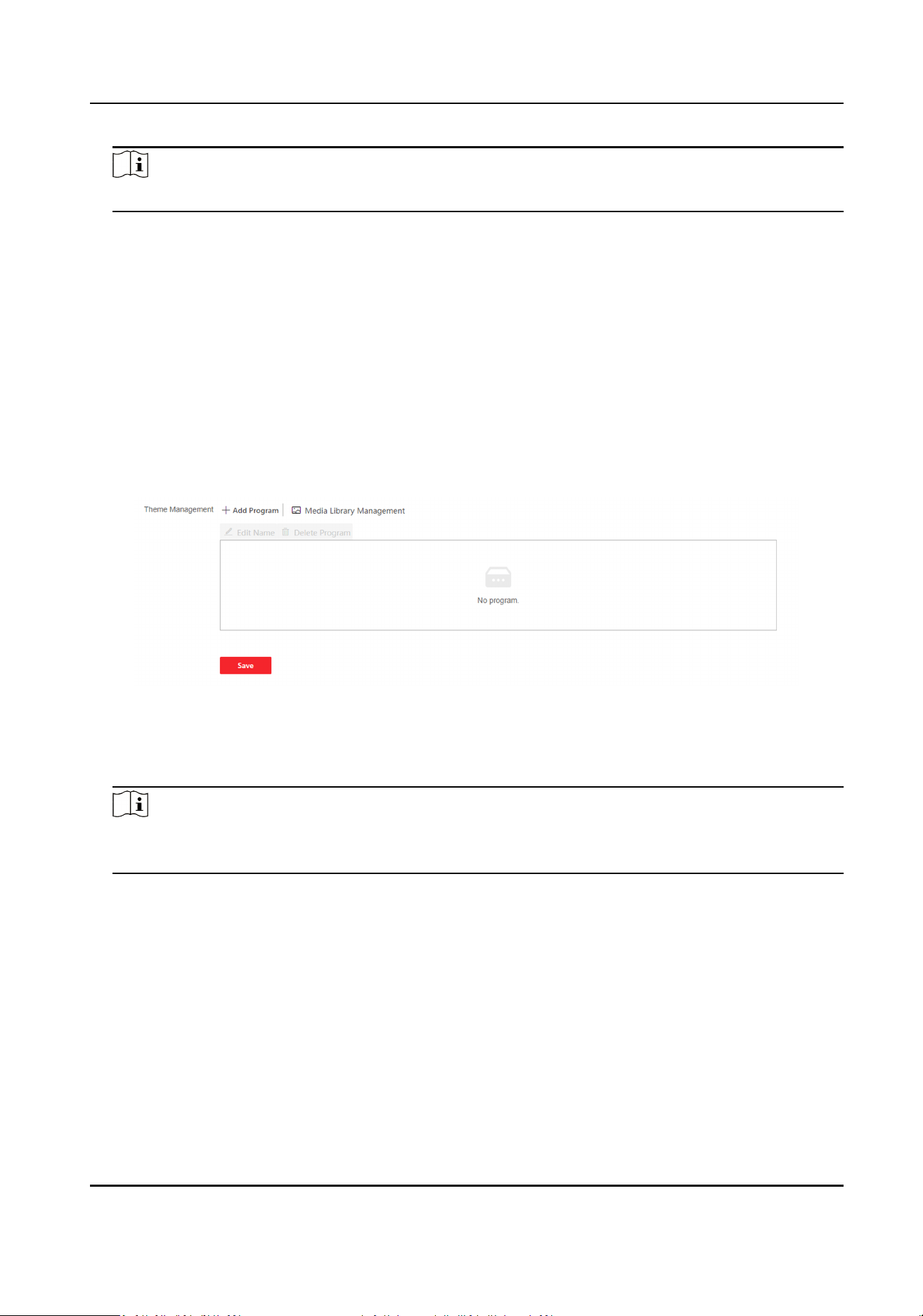
Note
The sleep me ranges from 20 s to 999 s.
Display Mode
You can select display theme for device authencaon. You can select Display Mode as Simple,
Authencaon Mode, or Adversement Mode. When you select Simple, the informaon of
name, ID, face picture will be not displayed. When you select
Adversement, the adversement
will be displayed in the screen.
10.6.18 Noce Publicaon
You can set the noce publicaon for the device.
Click Conguraon → Preference → Noce Publicaon .
Figure 10-6 Noce
Theme Management
Click Media Library Management → + to upload the picture from the local PC.
Note
Only the format of JPG and JPEG is supported. Each picture should be smaller than 1 MB with
resoluon up to 1920*1280.
Add Program
Click + Add Program. You can set the program name and select program type.
Picture
If you select picture, you can click + to add picture.
Welcome Message
If you select welcome message, you can set the template, content, font size and color of
main and sub tle. You can also custom the background picture.
Slide Show Interval
DS-K3B631TX Series Swing Barrier User Manual
80
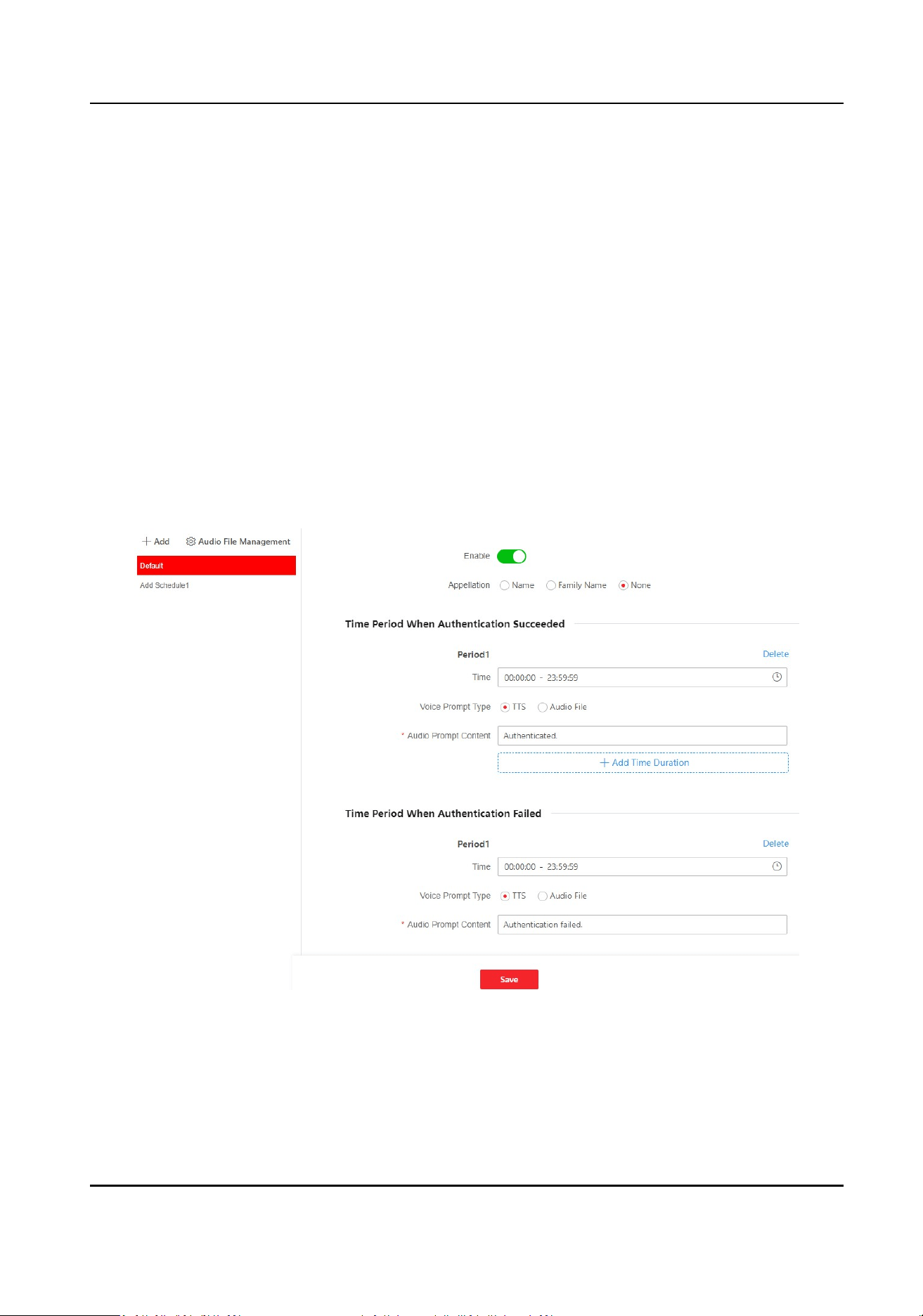
Drag the block or enter the number to set the slide show interval. The picture and video will be
changed according to the interval.
Schedule Management
Aer you have created a theme, click + Add on the schedule management panel. Select the
drawn schedule, and you can edit the exact start and end me.
Select the drawn schedule and you can click Clear or Clear All to delete the schedule.
Click Releasing Record to view task name, releasing status, etc.
Click View Terminal Schedule Info. to view terminal name, schedule name, etc.
10.6.19 Customize Audio Content
Customize the output audio content when authencaon succeeded and failed.
Steps
1.
Click
Conguraon → Preference → Prompt Schedule .
Figure 10-7 Customize Audio Content
2.
Click + Add to add a new schedule. Or select added me schedule.
3.
Enable the
funcon.
4.
Set the appellaon.
5.
Set the me period when authencaon succeeded.
DS-K3B631TX Series Swing Barrier User Manual
81
1) Click Add Time Duraon.
2) Set the me duraon.
Note
If authencaon is succeeded in the congured me duraon, the device will broadcast the
congured content.
3) Set the audio content.
TTS
If you choose TTS, you need to set the language and enter the prompt content of
authencaon success.
Audio File
If you choose audio le, you need to select an available audio le from the drop-down list
or click Audio File Management to add a new le.
Note
The audio le's format should be wav, and the size should be within 200 KB.
4) Oponal: Repeat substep 1 to 3.
5)
Oponal: Click Delete to delete the congured me duraon.
6.
Set the me duraon when authencaon failed.
1) Click Add Time
Duraon.
2) Set the me duraon.
Note
If authencaon is failed in the congured me duraon, the device will broadcast the
congured content.
3) Set the audio content.
TTS
If you choose TTS, you need to set the language and enter the prompt content of
authencaon failure.
Audio File
If you choose audio le, you need to select an available audio le from the drop-down list
or click Audio File Management to add a new le.
Note
The audio le's format should be wav, and the size should be within 200 KB.
4) Oponal: Repeat substep 1 to 3.
5)
Oponal: Click Delete to delete the congured me duraon.
7.
Click Save to save the sengs.
DS-K3B631TX Series Swing Barrier User Manual
82
10.6.20 Upgrade and Maintenance
Reboot device, restore device parameters, and upgrade device version.
Reboot Device
Click Maintenance and Security → Maintenance → Restart .
Click Restart to reboot the device.
Upgrade
Click Maintenance and Security → Maintenance → Upgrade .
Select an upgrade type from the drop-down list. Click and select the upgrade le from your
local PC. Click Upgrade to start upgrading.
If the device has been connected to Hik-Connect and network, when there is a new
installaon
package in Hik-Connect, you can click Upgrade aer Online Update to upgrade the device system.
Note
Do not power o during the upgrading.
Restore Parameters
Click Maintenance and Security → Maintenance → Backup and Reset .
Restore All
All parameters will be restored to the factory
sengs. You should acvate the device before
usage.
Restore
The device will restore to the default sengs, except for the network parameters and the user
informaon.
Import and Export Parameters
Click Maintenance and Security → Maintenance → Backup and Reset .
Export
Click Export to export the device parameters.
Note
You can import the exported device parameters to another device.
Import
Click and select the le to import. Click Import to start import conguraon le.
DS-K3B631TX Series Swing Barrier User Manual
83

10.6.21 Device Debugging
You can set device debugging parameters.
Steps
1.
Click Maintenance and Security → Maintenance → Device Debugging .
2.
You can set the following parameters.
Enable SSH
To raise network security, disable SSH service. The
conguraon is only used to debug the
device for the professionals.
Motor Study & Self-Test
Select the lane and click Start, the motor will test the
operaon status automacally.
Print Log
You can click Export to export log.
Capture Network Packet
You can set the Capture Packet Duraon, Capture Packet Size, and click Start to capture.
10.6.22 Component Status
Main Lane Status
Device Component
You can view the status of boards, IR adaptors and camera.
Peripheral
You can view the status of the card reader and tamper input.
Temperature
You can view the pedestal temperature.
Movement
You can view the working status of motor encoder.
Sub Lane Status
Device Component
You can view the status of boards, IR adaptors and camera.
Peripheral
You can view the status of the card reader and tamper input.
Temperature
You can view the pedestal temperature.
DS-K3B631TX Series Swing Barrier User Manual
84

Movement
You can view the working status of motor encoder.
Others
Passing Mode
You can view the entrance and exit mode.
IR Detector Status
You can view the status of each pair of the IR beam sensors.
Input and Output Status
You can view the status of the event input, alarm output and
re protecon alarm.
Other Status
You can view the status of the barrier and the keyfob receiving module.
10.6.23 Log Query
You can search and view the device logs.
Go to Maintenance and Security → Maintenance → Log .
Set the major and minor type of the log type. Set the start
me and end me for searching, and
click Search.
The results will be displayed below, which including the No.,
me, the major type the minor type,
the channel No., the local/remote user
informaon, the remote host IP, etc.
10.6.24 Advanced
Sengs
You can congure face parameters and view version informaon.
Go to Maintenance and Security → Maintenance → Advanced Sengs .
Select Entrance or Exit to congure parameters.
Face Parameter
Enable Lock Face for Authencaon, and set Lock Duraon. The face will be locked for the set lock
duraon aer the failed aempt limit of an-spoong detecon has been reached.
Click Unlock to cancel locking face.
Click Save.
Version
Informaon
You can see the dierent version informaon here.
DS-K3B631TX Series Swing Barrier User Manual
85

10.6.25 Cercate Management
It helps to manage the server/client cercates and CA cercate.
Note
The funcon is only supported by certain device models.
Create and Import Self-signed Cercate
Steps
1.
Go to Maintenance and Security → Security → Cercate Management .
2.
In the
Cercate Files area, select a Cercate Type from the drop-down list.
3.
Click Create.
4.
Input
cercate informaon.
5.
Click OK to save and install the cercate.
The created cercate is displayed in the Cercate Details area.
The
cercate will be saved automacally.
6.
Download the cercate and save it to an asking le in the local computer.
7.
Send the asking
le to a cercaon authority for signature.
8.
Import the signed cercate.
1) Select a cercate type in the Import Key area, and select a cercate from the local, and
click Import.
2) Select a cercate type in the Import Communicaon Cercate area, and select a cercate
from the local, and click Import.
Import Other Authorized
Cercate
If you already has an authorized cercate (not created by the device), you can import it to the
device directly.
Steps
1.
Go to Maintenance and Security → Security → Cercate Management .
2.
In the Import Key and Import Communicaon Cercate areas, select cercate type and
upload
cercate.
3.
Click Import.
Import CA
Cercate
Before You Start
Prepare a CA cercate in advance.
DS-K3B631TX Series Swing Barrier User Manual
86

Steps
1.
Go to Maintenance and Security → Security → Cercate Management .
2.
Create an ID in the Import CA Cercate area.
Note
The input cercate ID cannot be the same as the exisng ones.
3.
Upload a
cercate le from the local.
4.
Click Import.
DS-K3B631TX Series Swing Barrier User Manual
87

Chapter 11 Congure the Device via the Mobile
Browser
11.1 Login
You can login via mobile browser.
Note
Make sure the device is acvated.
Enter the device IP address in the address bar of the mobile browser and tap Enter to enter the
login page.
When the device hotpot is enabled, you can also scan the QR code and the login page will pop up.
Enter the user name and the password. Tap Login.
11.2 Overview
You can view the device status, conduct remote control, etc.
You can view the device status. If there is excepon, you can tap to view the component details.
You can remotely control barrier by tap the icons.
DS-K3B631TX Series Swing Barrier User Manual
88
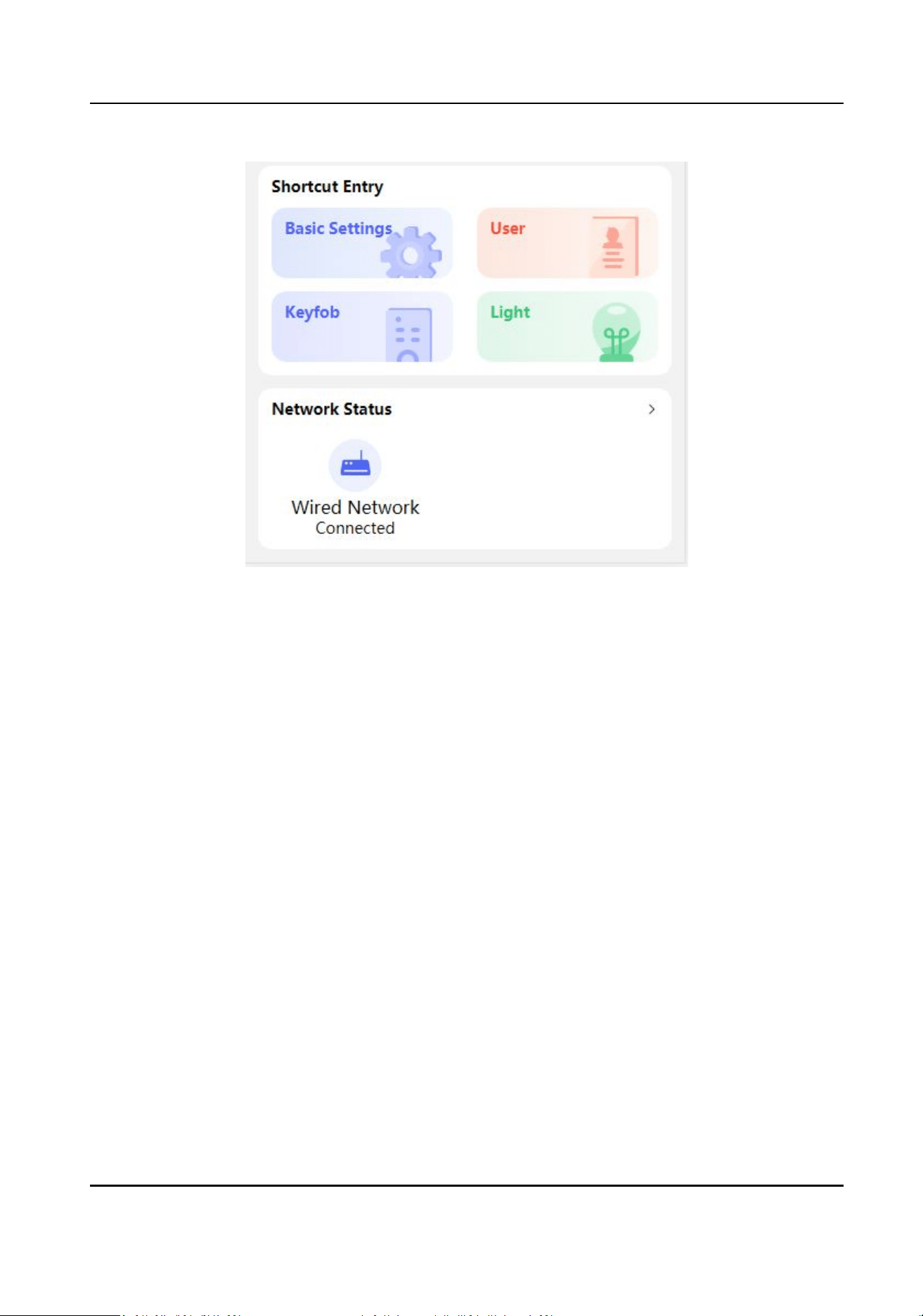
Figure 11-1 Shortcut Entry and Network Status
You can tap to fast enter the basic sengs page, user page, keyfob page, light page and network
page.
11.3
Conguraon
11.3.1 Turnsle Basic Parameters
You can set the basic parameters of the turnsle.
Tap Basic Sengs of the shortcut entry on the overview page.
DS-K3B631TX Series Swing Barrier User Manual
89
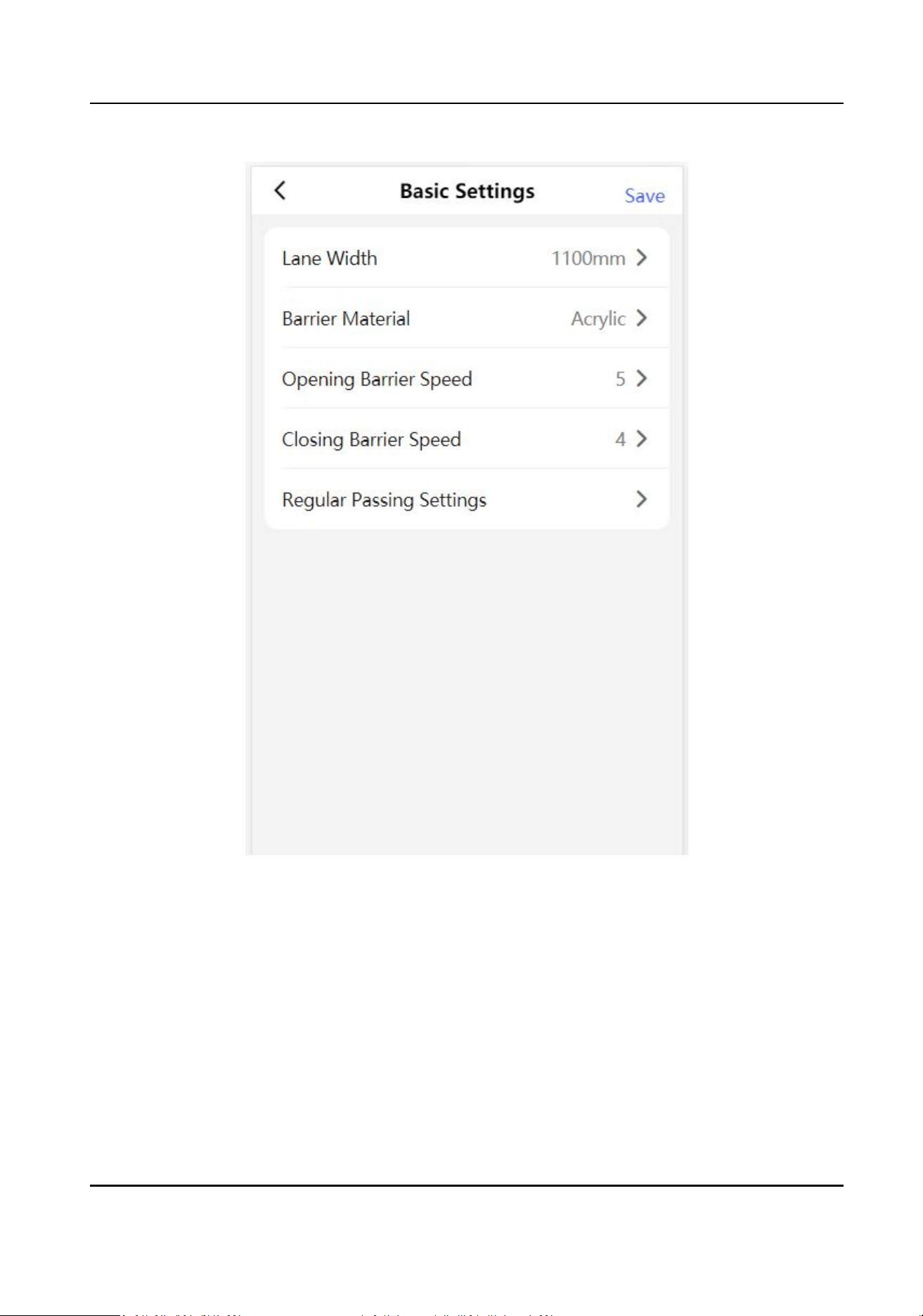
Figure 11-2 Turnsle Basic Parameters
Set Barrier Material, Lane Width, Barrier Opening Speed and Barrier Closing Speed.
Set the regular passing mode for the entrance and exit.
Tap Save.
11.3.2 User Management
You can add, edit, delete, and search users via mobile Web browser.
DS-K3B631TX Series Swing Barrier User Manual
90
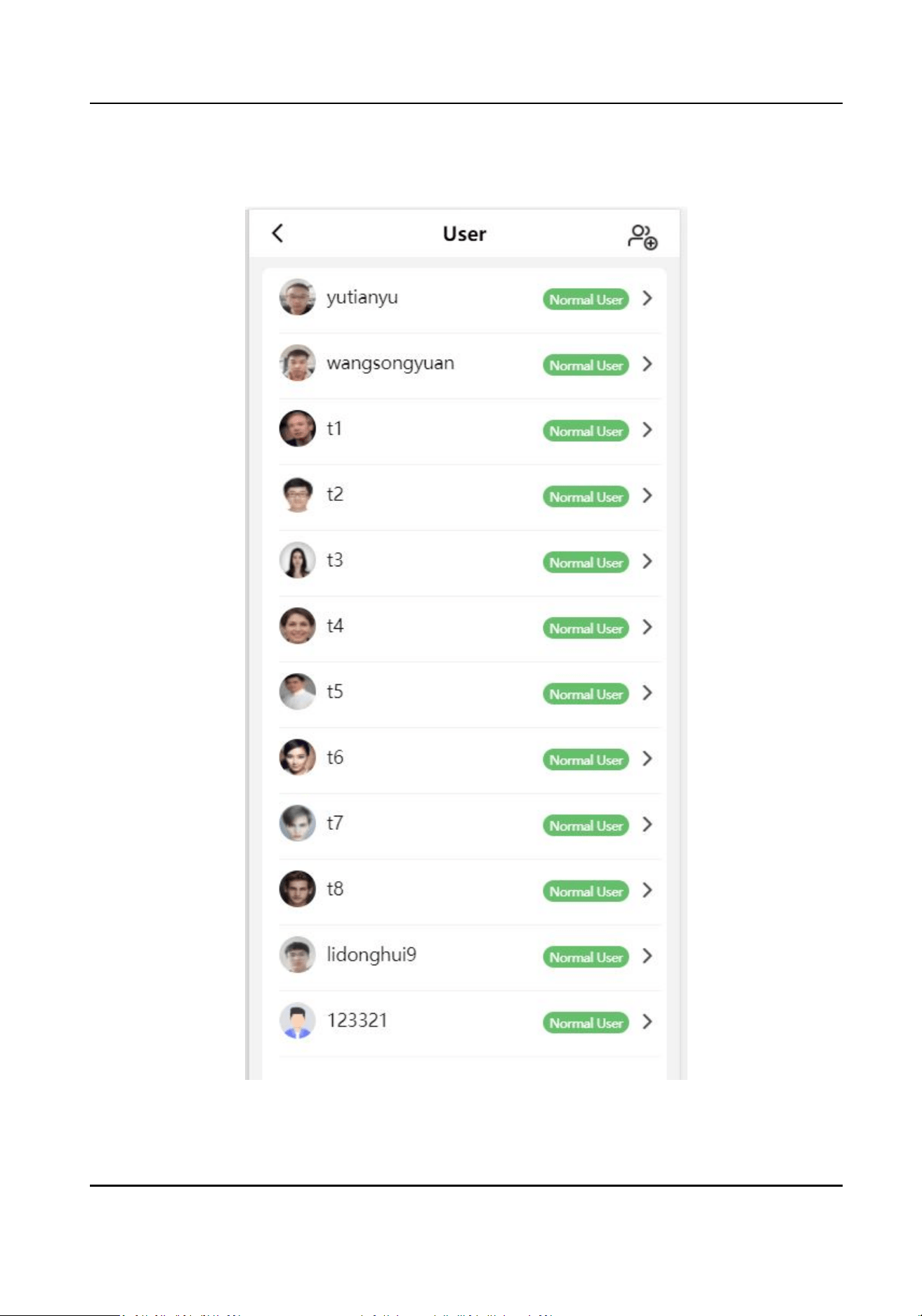
Steps
1.
Tap User to enter the sengs page.
Figure 11-3 Add User
DS-K3B631TX Series Swing Barrier User Manual
91

2.
Add user.
1) Tap .
2) Set the following parameters.
Employee ID
Enter the employee ID. The Employee ID cannot be 0 or exceed 32 characters. It can be a
combinaon of uppercase, lowercase leers and numbers.
Name
Enter your name. The name supports numbers, uppercase and lowercase English, and
characters. The name is recommended to be within 32 characters.
User Role
Select your user role.
Face
Add Face picture. Tap Face, and take a photo or choose picture from album to add.
Card
Add card. Tap Card → Add Card , enter the card No. and select the card type.
3) Tap Save.
3.
Tap the user that needs to be edited in the user list to edit the
informaon.
11.3.3 Keyfob
Sengs
Tap Keyfob of the shortcut entry on the overview page.
DS-K3B631TX Series Swing Barrier User Manual
92
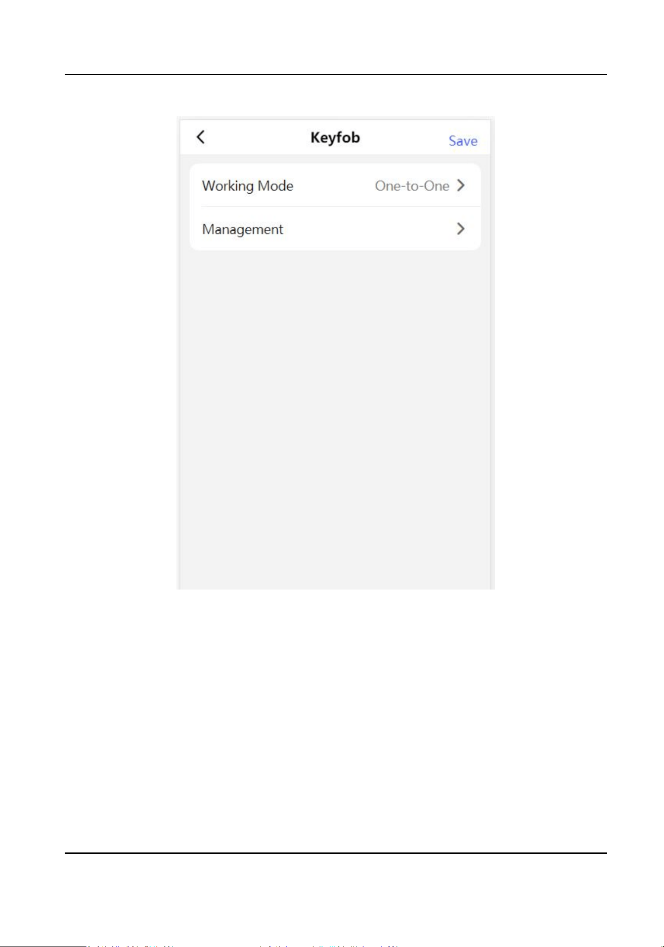
Figure 11-4 Keyfob Sengs
Set Working Mode as One-to-One or One-to-Many.
Tap Management to enter the page. Tap + to add keyfob. Set keyfob name, serial No. and remain
open permission.
11.3.4 Light
Sengs
Tap Light of the shortcut entry on the overview page.
DS-K3B631TX Series Swing Barrier User Manual
93
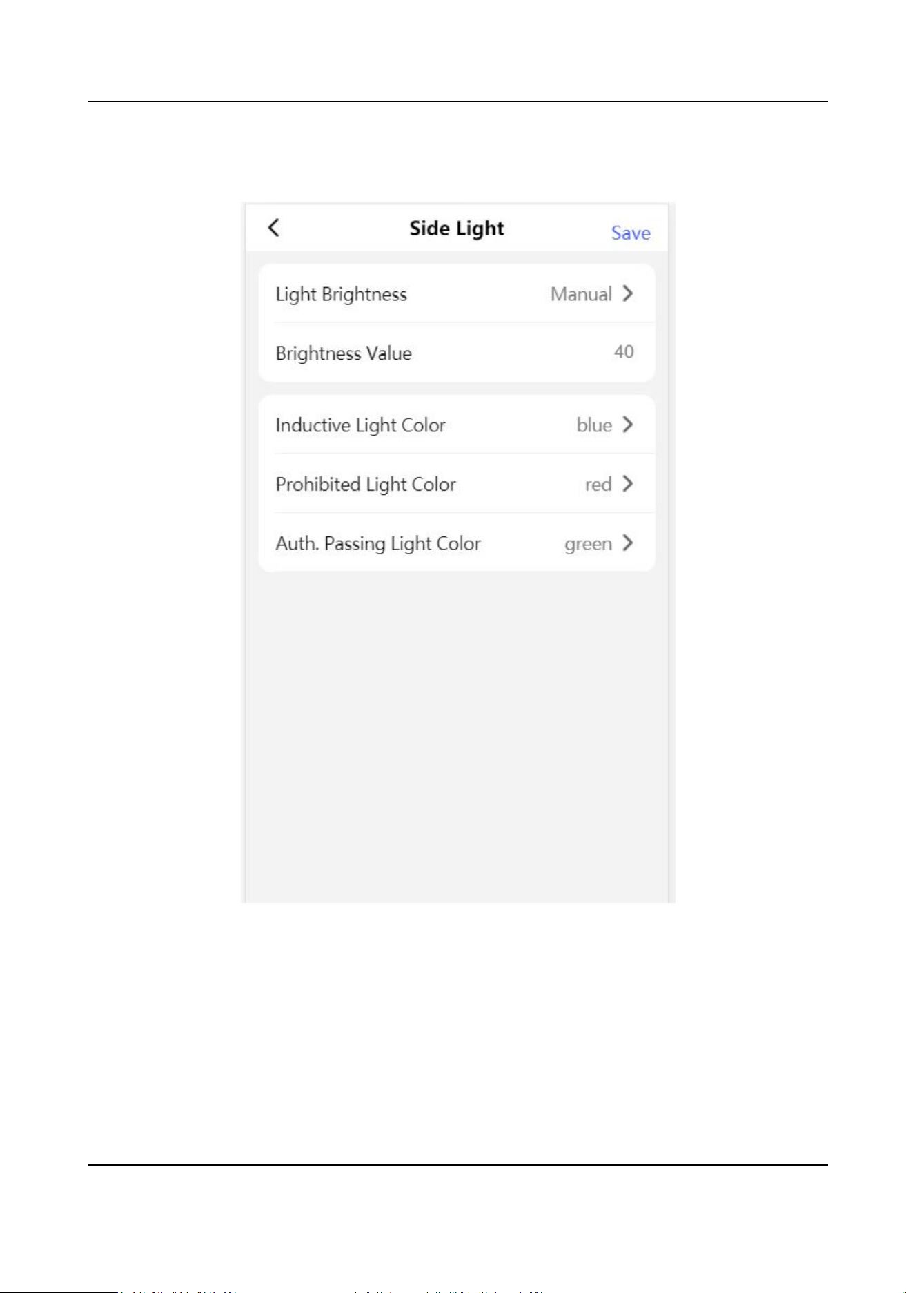
Side Light
Figure 11-5 Side Light Sengs
Set Light Brightness as Auto or Fixed Brightness. If you choose Fixed Brightness, you can enter the
value to adjust the light brightness manually.
Set
inducve, prohibited and Auth. passing light color.
DS-K3B631TX Series Swing Barrier User Manual
94
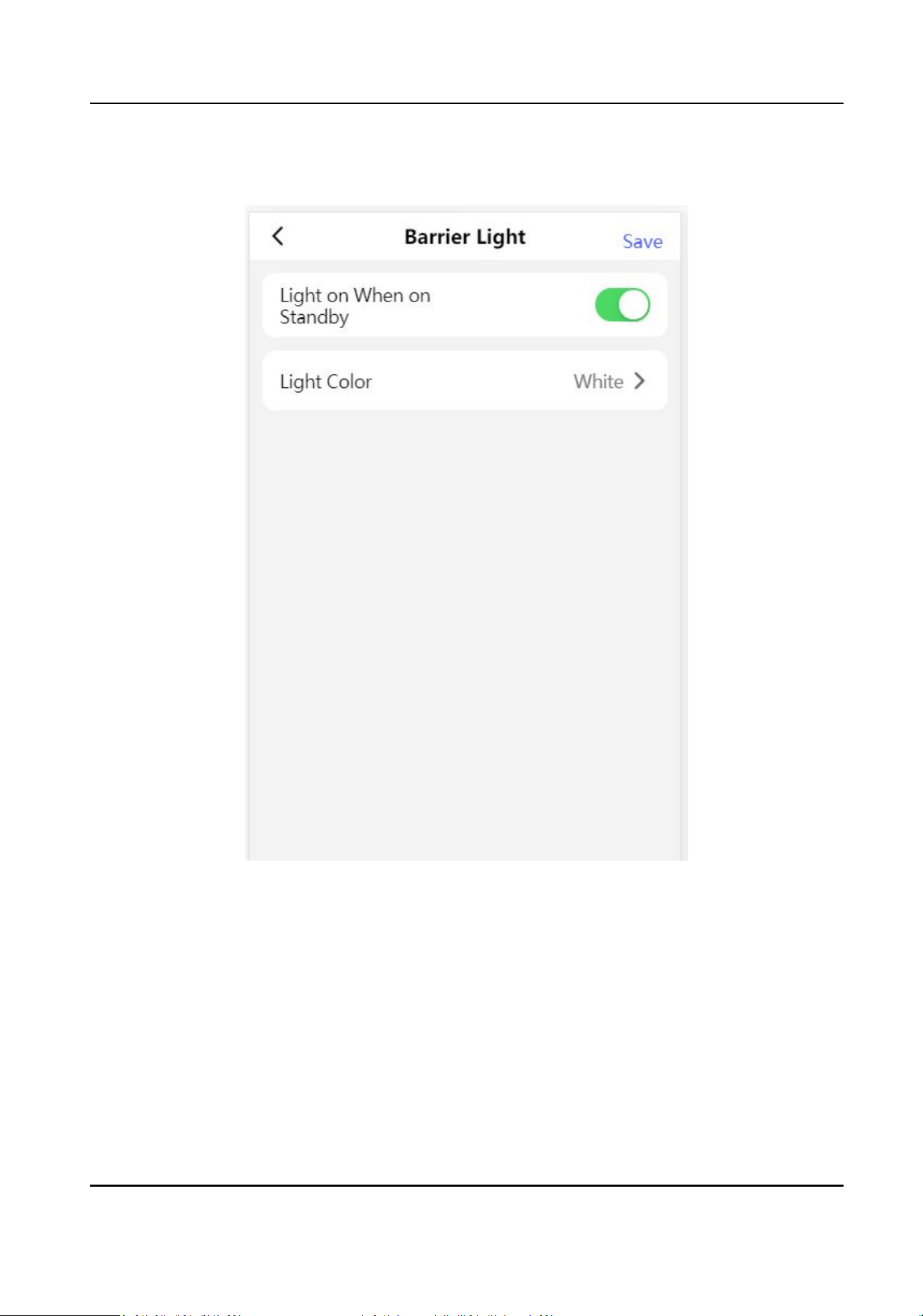
Barrier Light
Figure 11-6 Barrier Light Sengs
Tap to enable Light on When on Standby at your actual needs and set the barrier light color.
DS-K3B631TX Series Swing Barrier User Manual
95
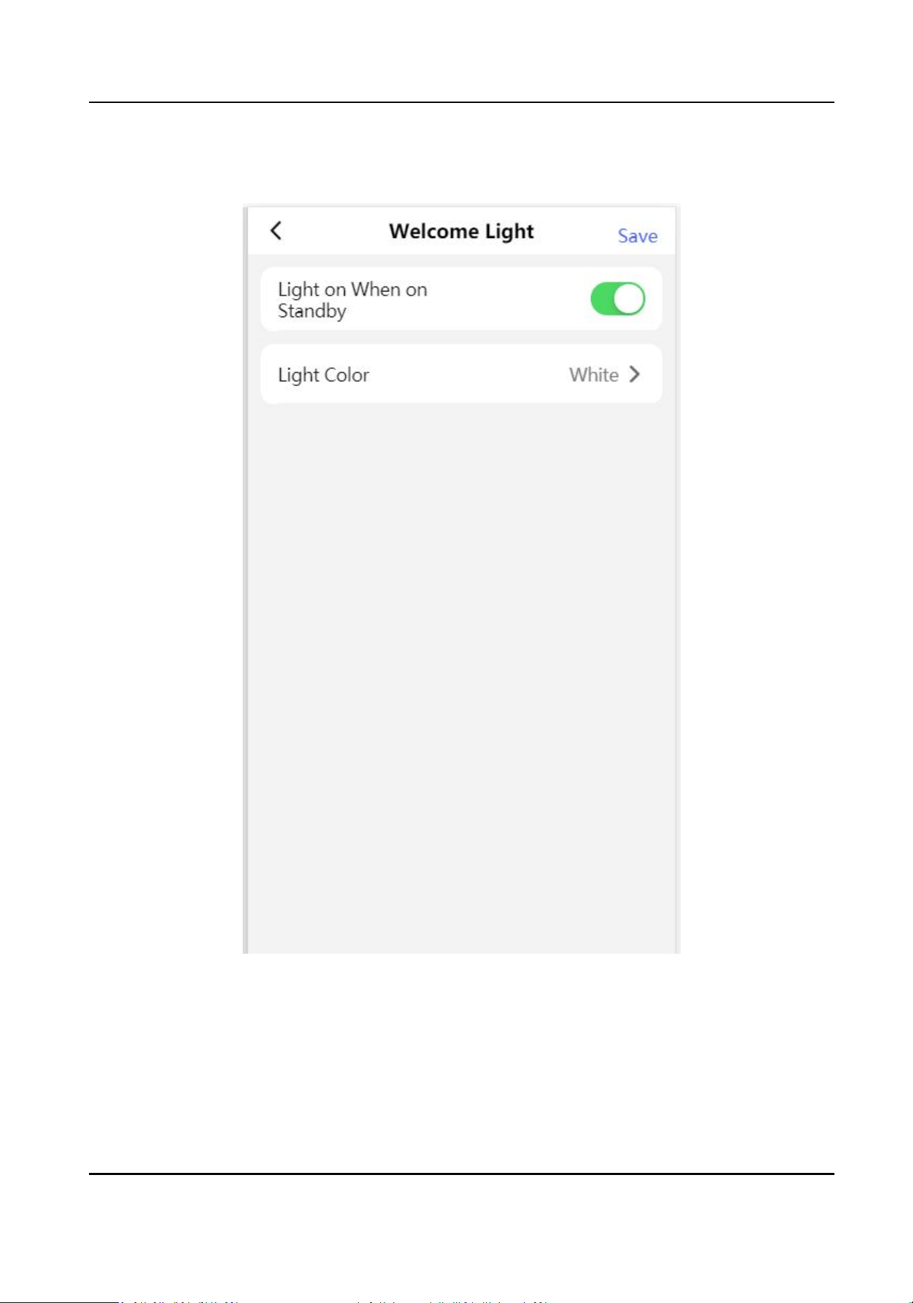
Welcome Light
Figure 11-7 Welcome Light Sengs
Tap to enable Light on When on Standby at your actual needs and set the welcome light color.
DS-K3B631TX Series Swing Barrier User Manual
96
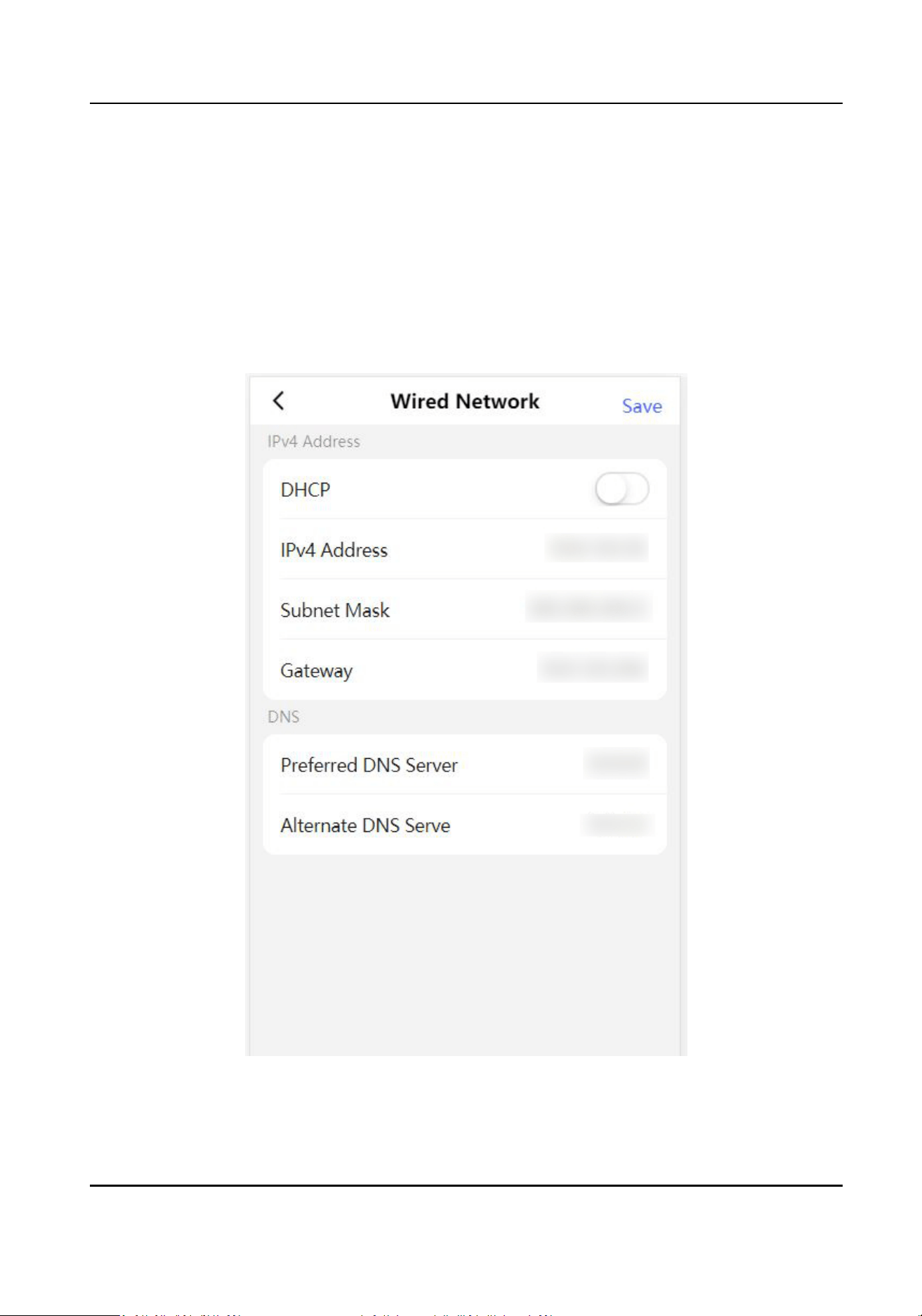
11.3.5 Network Sengs
You can set the wired network, device hotspot and port.
Wired Network
Set wired network.
Tap Conguraon → Communicaon Sengs → Wired Network to enter the conguraon page.
Figure 11-8 Wired Network
DS-K3B631TX Series Swing Barrier User Manual
97

DHCP
If you disable the funcon, you should set the IPv4 address, IPv4 subnet mask, IPv4 default
gateway, Mac address, and MTU.
If you enable the
funcon, the system will allocate the IPv4 address, IPv4 subnet mask, the IPv4
default gateway automacally.
DNS Server
Set the preferred DNS server and the Alternate DNS server according to your actual need.
Device Hotspot
Set device hotspot.
Tap Conguraon → Communicaon Sengs → Device Hotspot to enter the conguraon page.
DS-K3B631TX Series Swing Barrier User Manual
98
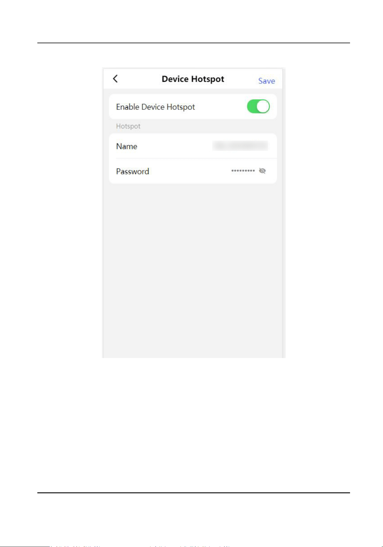
Figure 11-9 Device Hotspot
Tap to Enable Device Hotspot. Set hotspot Name and Password.
Click Save.
Serial Port
Conguraon
Set serial port.
Tap
Conguraon → Communicaon Sengs → Serial Port Conguraon to enter the
conguraon page.
DS-K3B631TX Series Swing Barrier User Manual
99
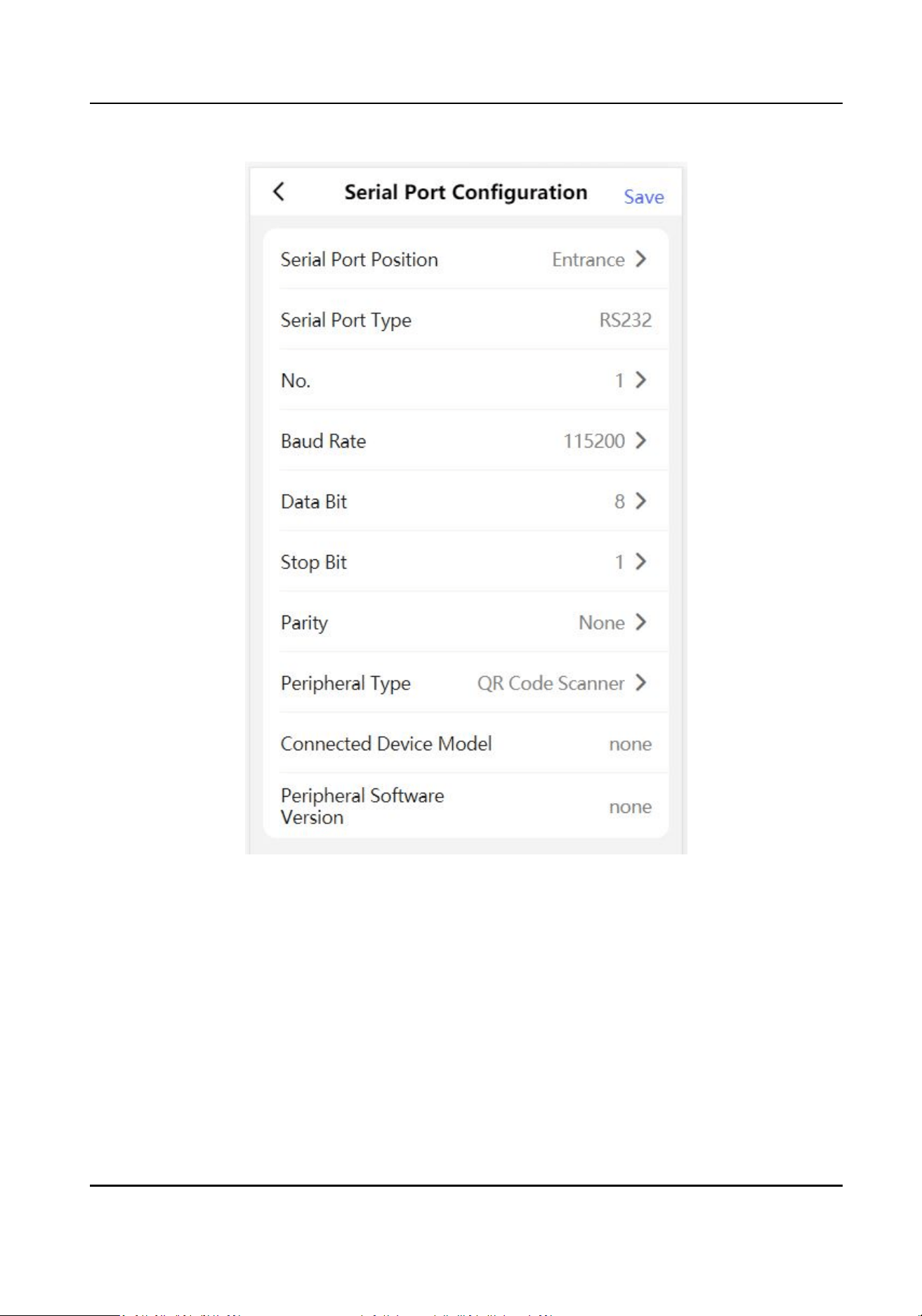
Figure 11-10 Serial Port Conguraon
Set Serial Port Posion as Entrance or Exit.
Select the port No., and set Baud Rate, Data Bit, Stop Bit and Parity.
Set the Peripheral Type as Card Receiver, QR Code Scanner or Disable.
Tap Save.
11.3.6 Device Basic
Sengs
Set audio, me, sleep me and privacy.
DS-K3B631TX Series Swing Barrier User Manual
100
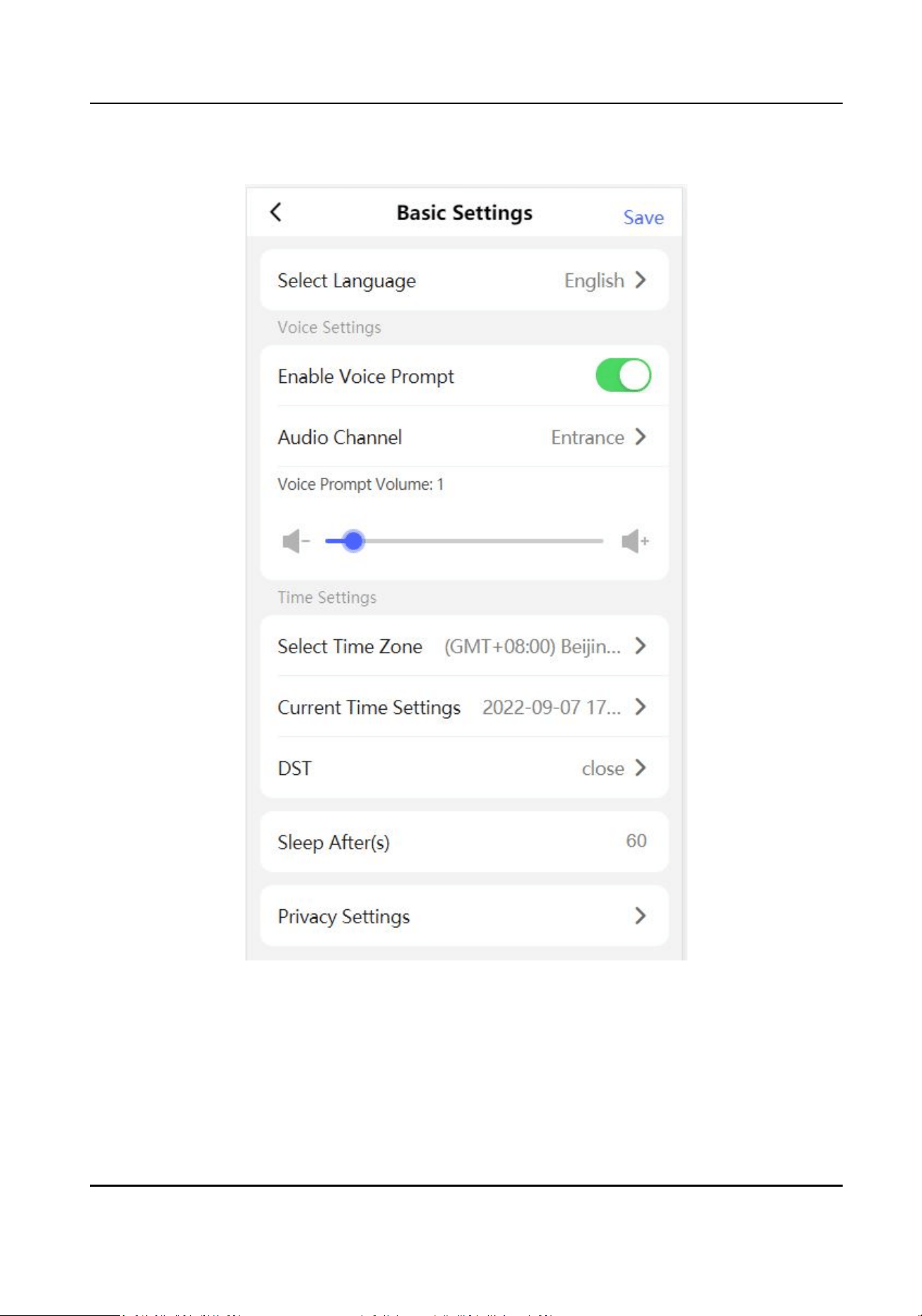
Tap Conguraon → Basic Sengs to enter the conguraon page.
Figure 11-11 Basic Conguraon
Language
The language is set English by default.
Voice Sengs
DS-K3B631TX Series Swing Barrier User Manual
101

Tap to Enable Voice Prompt, select entrance or exit to set voice prompt and drag to set the
volume.
Time Sengs
Tap to select the me zone and the device me.
Tap DST to enter the DST seng page. Set the DST start me, end me and bias me
Sleep
Set the device sleep
me.
Privacy
Authencaon Sengs
Display Authencaon Result
You can check Face Picture, Name, and Employee ID, to display the authencaon result.
Name De-idencaon
You can check Name De-idencaon, and the whole name will not be displayed.
ID De-idencaon
You can check ID De-idencaon, and the ID will not be displayed.
Picture Uploading and Storage
Save Pictures Aer Linked Capture
If you enable this funcon, you can save the picture captured by linked camera to the
device.
Upload Picture Aer Linked Capture
Upload the pictures captured by linked camera to the plaorm automacally.
11.3.7 Access Control
Sengs
Set Door Parameters
Tap Conguraon → Access Control → Door Parameters .
DS-K3B631TX Series Swing Barrier User Manual
102
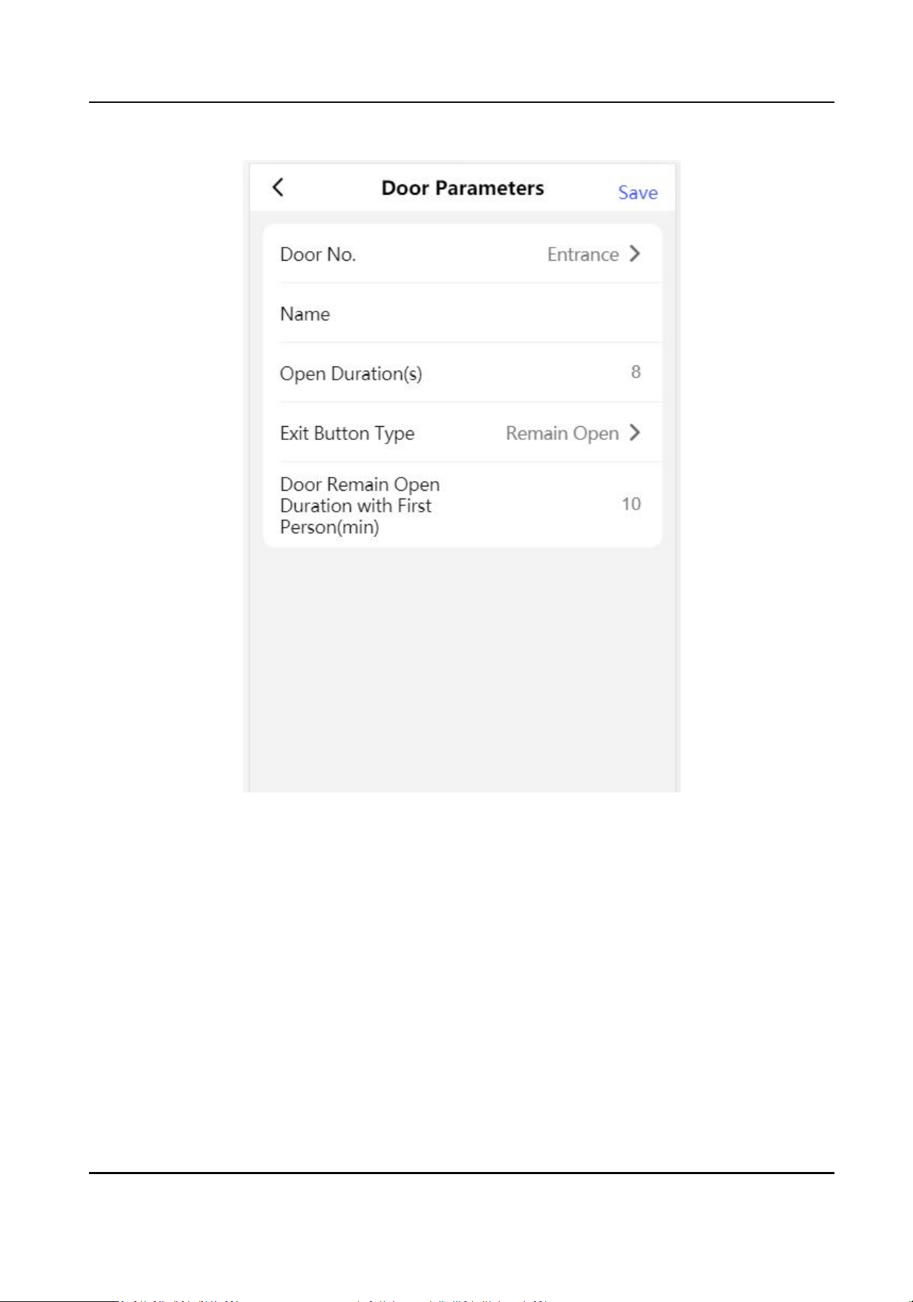
Figure 11-12 Door Parameters Sengs Page
Click Save to save the sengs aer the conguraon.
Door No.
Select the device corresponded door No.
Name
You can create a name for the door.
Open
Duraon
Set the door unlocking duraon. If the door is not opened for the set me, the door will be
locked.
Exit Buon Type
DS-K3B631TX Series Swing Barrier User Manual
103

You can set the exit buon as Remain Open or Remain Closed according to your actual needs.
By default, it is Remain Open.
Door Remain Open Duraon with First Person
Set the door open duraon when rst person is in. Aer the rst person is authorized, it allows
mulple persons access the door or other authencaon acons.
Set Authencaon Parameters
Set Authencaon Parameters.
Steps
1.
Tap
Conguraon → Access Control → Authencaon Sengs .
DS-K3B631TX Series Swing Barrier User Manual
104
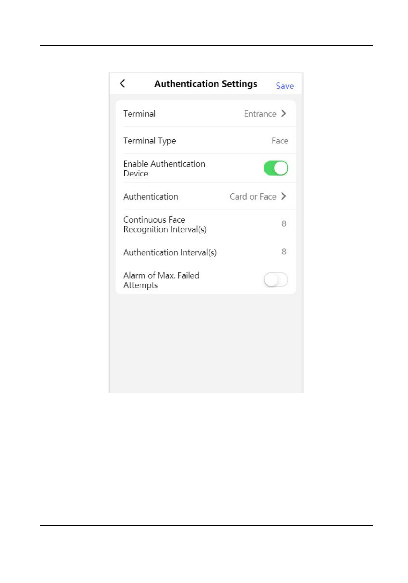
Figure 11-13 Authencaon Sengs
2.
Tap Save.
Terminal
Choose Entrance or Exit for sengs.
Enable Authencaon Device
Enable the authencaon funcon.
Authencaon
Select an authencaon mode according to your actual needs from the drop-down list.
DS-K3B631TX Series Swing Barrier User Manual
105

Connuous Recognion Interval
You can set the interval between 2 connuous recognion of a same person during the
authencaon. In the congured interval, Person A can only recognized once. If another
person (Person B) has recognized during the interval, Person A can recognized again.
Note
The recognion internal value ranges from 1 to 10.
Authencaon
Interval
You can set the authencaon interval of the same person when authencang. The same
person can only
authencate once in the congured interval. A second authencaon will be
failed.
Alarm of Max. Failed Aempts
Enable to report alarm when the card reading aempts reach the set value.
Set Card Security
Tap Conguraon → Access Control → Card Security to enter the sengs page.
DS-K3B631TX Series Swing Barrier User Manual
106
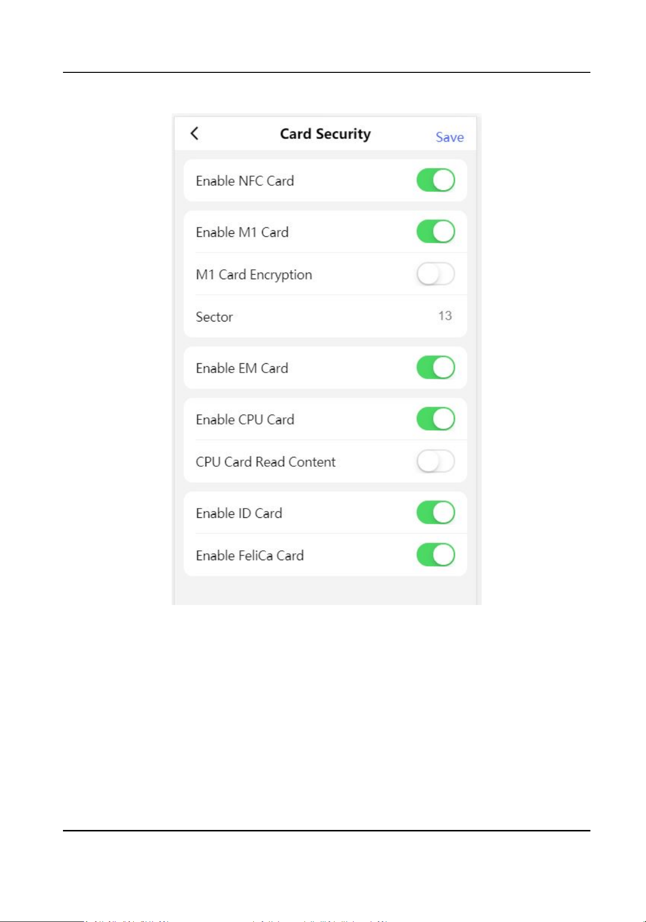
Figure 11-14 Card Security
Set the parameters and click Save.
Enable NFC Card
In order to prevent the mobile phone from geng the data of the access control, you can
disable NFC card to increase the security level of the data.
Enable M1 Card
Enable M1 card and
authencang by presenng M1 card is available.
M1 Card Encrypon
M1 card encrypon can improve the security level of authencaon.
DS-K3B631TX Series Swing Barrier User Manual
107

Sector
Enable the funcon and set the encrypon sector. By default, Sector 13 is encrypted. It is
recommended to encrypt sector 13.
Enable EM Card
Enable EM card and
authencang by presenng EM card is available.
Note
If the peripheral card reader supports presenng EM card, the funcon is also supported to
enable/disable the EM card funcon.
Enable CPU Card
The device can read the data from CPU card when enabling the CPU card funcon.
CPU Card Read Content
Aer enable the CPU card content reading funcon, the device can read the CPU card content.
Enable ID Card
Enable ID card and authencang by presenng ID card is available.
Enable FeliCa Card
The device can read the data from FeliCa card when enabling the FeliCa card funcon.
Terminal
Sengs
Set the working mode.
Tap Conguraon → Access Control → Terminal Parameters to enter the sengs page.
DS-K3B631TX Series Swing Barrier User Manual
108
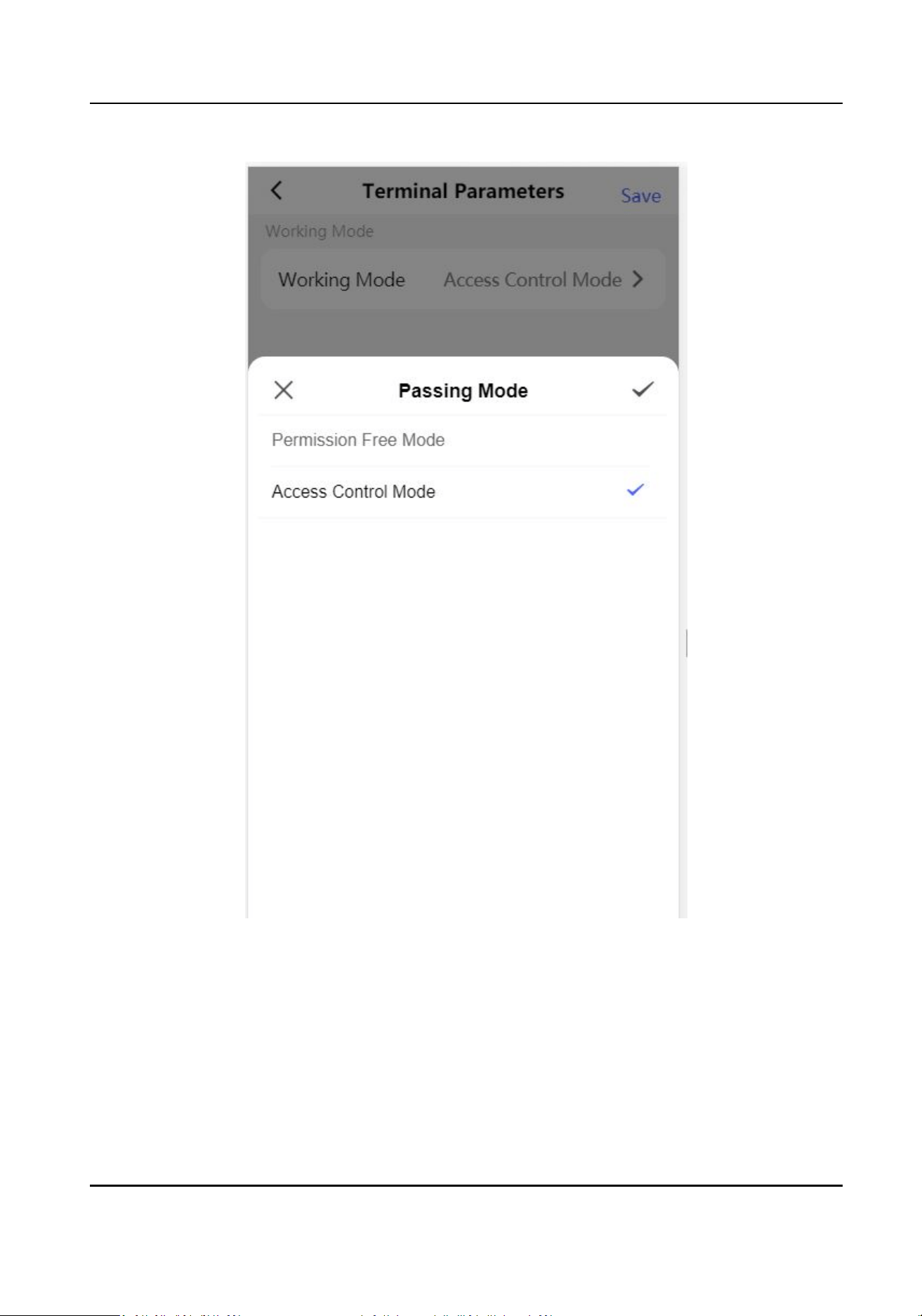
Figure 11-15 Terminal Parameters
Permission Free Mode
The device will not verify the person's permission, but only the person's validity period. If the
person is in the validity period, the barrier will open.
You can enable Verify
Credenal Locally. Aer enabling the funcon, the device will only verify
the person's permission without the schedule template, etc.
Access Control Mode
DS-K3B631TX Series Swing Barrier User Manual
109

The device works normally and will verify the person's permission to open the barrier.
11.3.8 Face Parameters Sengs
Set face parameters.
Face Parameters Sengs
Tap Conguraon → Biometrics .
DS-K3B631TX Series Swing Barrier User Manual
110
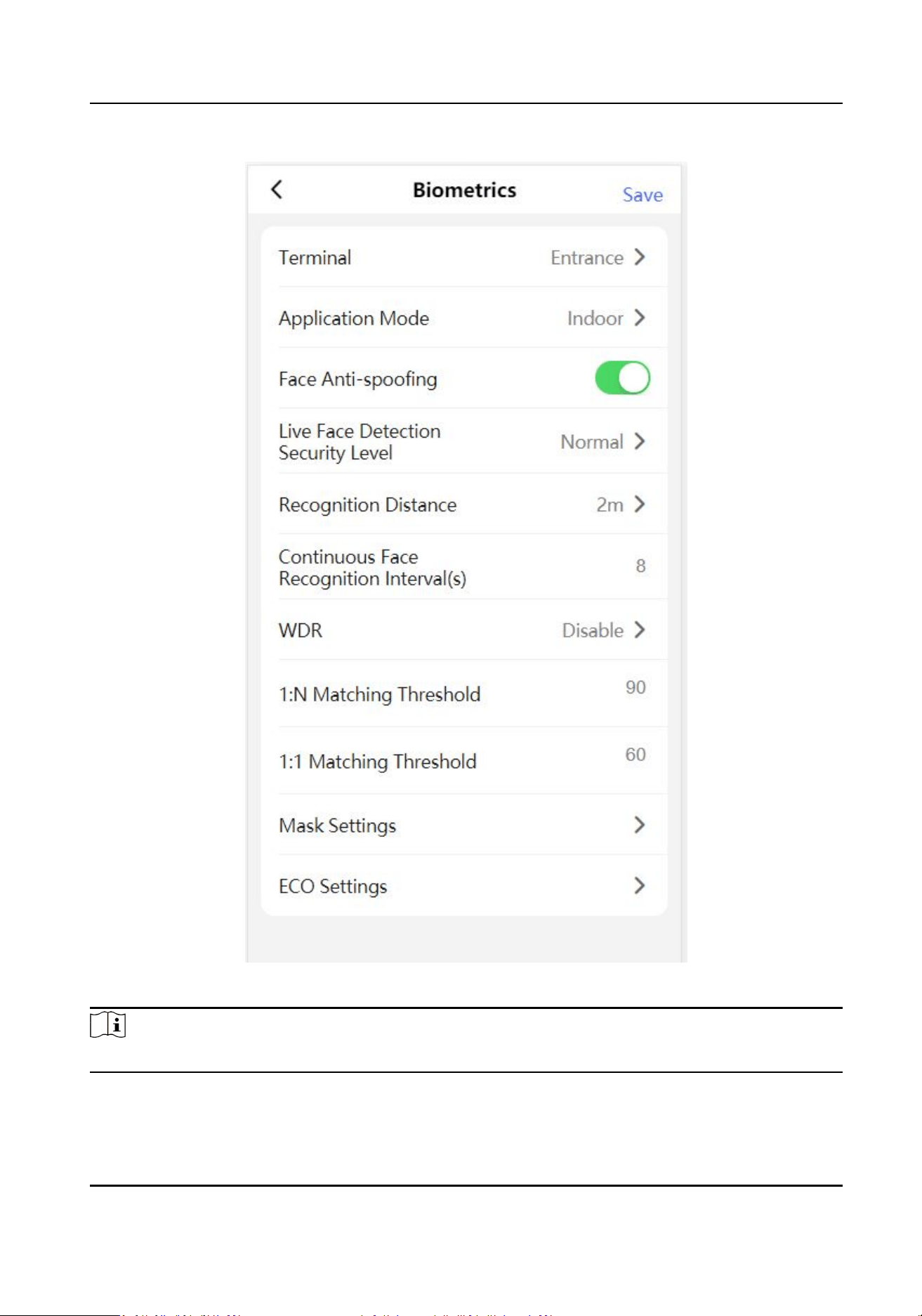
Figure 11-16 Face Parameters
Note
The funcons vary according to dierent models. Refers to the actual device for details.
Set Face Parameters.
DS-K3B631TX Series Swing Barrier User Manual
111

Terminal
Choose Entrance or Exit for sengs.
Face Recognion Mode
Normal Mode
Recognize face via the camera normally.
Deep Mode
The device can recognize a much wider people range than the normal mode. This mode is
applicable to a more complicated environment.
Enable Face
Recognion
If enabling the funcon, the device will start face recognion.
Face An-spoong
Enable or disable the live face detecon funcon. If enabling the funcon, the device can
recognize whether the person is a live one or not.
Note
Biometric recognion products are not 100% applicable to an-spoong environments. If you
require a higher security level, use mulple authencaon modes.
Live Face Detecon Security Level
Aer enabling the face an-spoong funcon, you can set the matching security level when
performing live face authencaon.
Recognion Distance
Select the distance between the authencang user and the device camera.
Applicaon Mode
Select either others or indoor according to actual environment.
Pitch Angle
The maximum pitch angle when starng face authencaon.
Yaw Angle
The maximum yaw angle when starng face authencaon.
1:1 Matching Threshold
Set the matching threshold when authencang via 1:1 matching mode. The larger the value,
the smaller the false accept rate and the larger the false rejecon rate.
1:N Matching Threshold
Set the matching threshold when authencang via 1:N matching mode. The larger the value,
the smaller the false accept rate and the larger the false
rejecon rate.
Face Recognion Timeout Value
DS-K3B631TX Series Swing Barrier User Manual
112

Set the meout value when face recognizing. If the face recognion me is longer than the
congured value, the system will pop up a prompt.
Face without Mask Detecon
Aer enabling the face without mask detecon, the system will recognize the captured face
with mask picture or not. You can set face with mask1:N matching threshold, it's ECO mode, and
the strategy.
None
The
funcon is disabled. The device will not detect whether a person is wearing a face mask
or not.
Reminder of Wearing
If the person do not wear the face mask when
authencang, the device will pop up a
prompt and the door will open.
Must Wear
If the person do not wear the face mask when authencang, the device will pop up a
prompt and the door will keep closed.
Face with Mask 1:N Matching Threshold
Set the matching threshold when
authencang with face mask via 1:N matching mode. The
larger the value, the smaller the false accept rate and the larger the false rejecon rate.
ECO Mode
Aer enabling the ECO mode, the device will use the IR camera to authencate faces in the low
light or dark environment. And you can set the ECO mode threshold, ECO mode (1:N), and ECO
mode (1:1).
ECO Mode (1:1)
Set the matching threshold when
authencang via ECO mode 1:1 matching mode. The larger
the value, the smaller the false accept rate and the larger the false
rejecon rate.
ECO Mode (1:N)
Set the matching threshold when authencang via ECO mode 1:N matching mode. The larger
the value, the smaller the false accept rate and the larger the false rejecon rate
Face with Mask & Face (1:1 ECO)
Set the matching value when authencang with face mask via ECO mode 1:1 matching mode.
The larger the value, the smaller the false accept rate and the larger the false
rejecon rate.
Face with Mask 1:N Matching Threshold (ECO Mode)
Set the matching threshold when authencang with face mask via ECO mode 1:N matching
mode. The larger the value, the smaller the false accept rate and the larger the false rejecon
rate.
DS-K3B631TX Series Swing Barrier User Manual
113

11.3.9 View Device Informaon
View the device name, language, model, serial No., QR code, version, etc.
Tap
Conguraon → System Informaon to enter the conguraon page.
You can view the device name, language, model, serial No., version, number of channels, IO input
and output number, local RS-485 number, MAC address and open source license.
11.3.10 Device Capacity
Tap Conguraon → Device Capacity to enter the page.
You can view the
quanty of user, face, card and event.
11.3.11 Log Export
Tap Conguraon → Log Export to enter the page.
Select a log type and tap Export.
11.3.12 Restore and Reboot
Reboot device and restore device parameters.
Restore
Tap Conguraon → Restore .
All parameters will be restored to the factory
sengs.
Restart Devices
Tap Conguraon → Restart Devices .
Tap Reboot to reboot the device.
DS-K3B631TX Series Swing Barrier User Manual
114
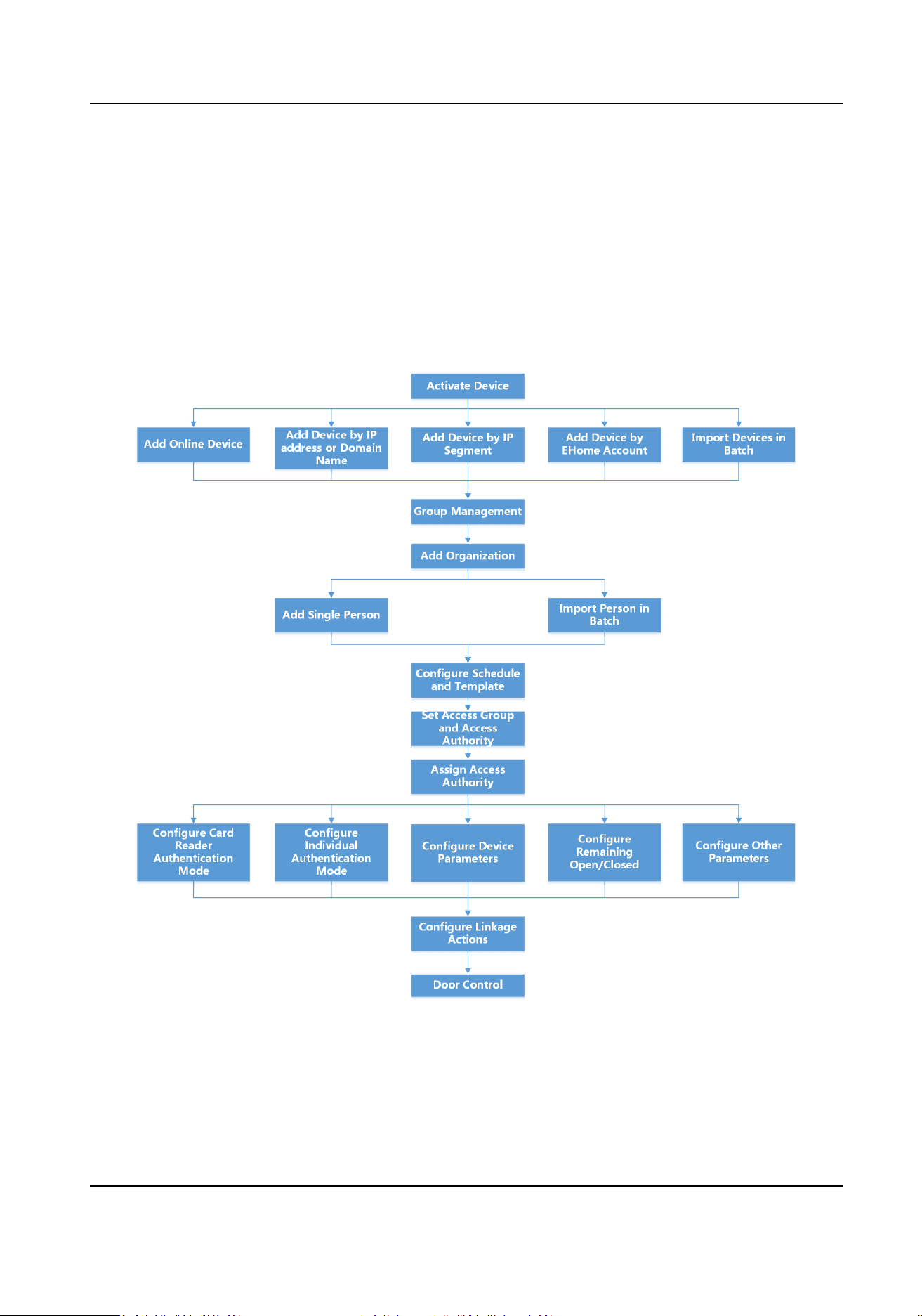
Chapter 12 Client Soware Conguraon
You can call the hotline to get the iVMS-4200 client soware installaon package.
12.1 Conguraon Flow of Client Soware
Follow the ow diagram below to congure on the client soware.
Figure 12-1 Flow Diagram of Conguraon on Client Soware
DS-K3B631TX Series Swing Barrier User Manual
115

12.2 Device Management
The client supports managing access control devices and video intercom devices.
Example
You can control entrance & exit and manage aendance aer adding access control devices to the
client; you can perform video intercom with the indoor staons and door staons.
12.2.1 Add Device
The client provides three device adding modes including by IP/domain, IP segment, and EHome
protocol. The client also supports imporng mulple devices in a batch when there are large
amount of devices to be added.
Add Device by IP Address or Domain Name
If you know the IP address or domain name of the device to add, you can add devices to the client
by specifying the IP address (or domain name), user name, password, etc.
Steps
1.
Enter Device Management module.
2.
Click Device tab on the top of the right panel.
The added devices are displayed on the right panel.
3.
Click Add to open the Add window, and then select IP/Domain as the adding mode.
4.
Enter the required
informaon.
Name
Create a descripve name for the device. For example, you can use a nickname that can show
the locaon or feature of the device.
Address
The IP address or domain name of the device.
Port
The devices to add share the same port number. The default value is 8000.
Note
For some device types, you can enter 80 as the port No. This funcon should be supported by
the device.
User Name
Enter the device user name. By default, the user name is admin.
Password
DS-K3B631TX Series Swing Barrier User Manual
116
Enter the device password.
Cauon
The password strength of the device can be automacally checked. We highly recommend
you change the password of your own choosing (using a minimum of 8 characters, including
at least three kinds of following categories: upper case leers, lower case leers, numbers,
and special characters) in order to increase the security of your product. And we recommend
you change your password regularly, especially in the high security system, changing the
password monthly or weekly can
beer protect your product.
Proper conguraon of all passwords and other security sengs is the responsibility of the
installer and/or end-user.
5.
Oponal: Check Transmission Encrypon (TLS) to enable transmission encrypon using TLS
(Transport Layer Security) protocol for security purpose.
Note
●
This funcon should be supported by the device.
●
If you have enabled Cercate Vericaon, you should click Open Cercate Directory to
open the default folder, and copy the cercate le exported from the device to this default
directory to strengthen the security. See for details about enabling
cercate vericaon.
●
You can log into the device to get the
cercate le by web browser.
6.
Check Synchronize Time to synchronize the device me with the PC running the client aer
adding the device to the client.
7.
Oponal: Check Import to Group to create a group by the device name, and import all the
channels of the device to this group.
Example
For access control device, its access points, alarm inputs/outputs, and encoding channels (if
exist) will be imported to this group.
8.
Finish adding the device.
-
Click Add to add the device and back to the device list page.
-
Click Add and New to save the sengs and connue to add other device.
Import Devices in a Batch
You can add mulple devices to the client in a batch by entering the device parameters in a pre-
dened CSV le.
Steps
1.
Enter the Device Management module.
2.
Click Device tab on the top of the right panel.
3.
Click Add to open the Add window, and then select Batch Import as the adding mode.
4.
Click Export Template and then save the
pre-dened template (CSV le) on your PC.
DS-K3B631TX Series Swing Barrier User Manual
117
5.
Open the exported template le and enter the required informaon of the devices to be added
on the corresponding column.
Note
For detailed descripon of the required elds, refer to the introducons in the template.
Adding Mode
Enter 0 or 1 or 2.
Address
Edit the address of the device.
Port
Enter the device port number. The default port number is 80.
User Name
Enter the device user name. By default, the user name is admin.
Password
Enter the device password.
Cauon
The password strength of the device can be automacally checked. We highly recommend
you change the password of your own choosing (using a minimum of 8 characters, including
at least three kinds of following categories: upper case leers, lower case leers, numbers,
and special characters) in order to increase the security of your product. And we recommend
you change your password regularly, especially in the high security system, changing the
password monthly or weekly can
beer protect your product.
Proper conguraon of all passwords and other security sengs is the responsibility of the
installer and/or end-user.
Import to Group
Enter 1 to create a group by the device name. All the channels of the device will be imported
to the corresponding group by default. Enter 0 to disable this funcon.
6.
Click and select the template le.
7.
Click Add to import the devices.
12.2.2 Reset Device Password
If you forgot the password of the detected online devices, you can reset the device password via
the client.
Steps
1.
Enter Device Management page.
2.
Click Online Device to show the online device area.
DS-K3B631TX Series Swing Barrier User Manual
118
All the online devices sharing the same subnet will be displayed in the list.
3.
Select the device from the list and click on the Operaon column.
4.
Reset the device password.
-
Click Generate to pop up the QR Code window and click Download to save the QR code to
your PC. You can also take a photo of the QR code to save it to your phone. Send the picture
to our technical support.
Note
For the following operaons for reseng the password, contact our technical support.
Cauon
The password strength of the device can be automacally checked. We highly recommend you
change the password of your own choosing (using a minimum of 8 characters, including at least
three kinds of following categories: upper case leers, lower case leers, numbers, and special
characters) in order to increase the security of your product. And we recommend you change
your password regularly, especially in the high security system, changing the password monthly
or weekly can
beer protect your product.
Proper conguraon of all passwords and other security sengs is the responsibility of the
installer and/or end-user.
12.2.3 Manage Added Devices
Aer adding devices to device list, you can manage the added devices including eding device
parameters, remote conguraon, viewing device status, etc.
Table 12-1 Manage Added Devices
Edit Device Click to edit device informaon including device name, address, user
name, password, etc.
Delete Device Check one or more devices, and click Delete to delete the selected
devices.
Remote Conguraon Click to set remote conguraon of the corresponding device. For
details, refer to the user manual of device.
View Device Status Click to view device status, including door No., door status, etc.
Note
For dierent devices, you will view dierent informaon about device
status.
DS-K3B631TX Series Swing Barrier User Manual
119
View Online User Click to view the details of online user who access the device,
including user name, user type, IP address and login me.
Refresh Device
Informaon
Click to refresh and get the latest device informaon.
12.3 Group Management
The client provides groups to manage the added resources in dierent groups. You can group the
resources into dierent groups according to the resources' locaons.
Example
For example, on the 1st
oor, there mounted 16 doors, 64 alarm inputs, and 16 alarm outputs. You
can organize these resources into one group (named 1st Floor) for convenient management. You
can control door status, and do some other
operaons of the devices aer managing the resources
by groups.
12.3.1 Add Group
You can add group to organize the added device for convenient management.
Steps
1.
Enter the Device Management module.
2.
Click Device Management → Group to enter the group management page.
3.
Create a group.
-
Click Add Group and enter a group name as you want.
-
Click Create Group by Device Name and select an added device to create a new group by the
name of the selected device.
Note
The resources (such as alarm inputs/outputs, access points, etc.) of this device will be
imported to the group by default.
12.3.2 Import Resources to Group
You can import the device resources (such as alarm inputs/outputs, access points, etc.) to the
added group in a batch.
Before You Start
Add a group for managing devices. Refer to Add Group .
Steps
1.
Enter the Device Management module.
DS-K3B631TX Series Swing Barrier User Manual
120
2.
Click Device Management → Group to enter the group management page.
3.
Select a group from the group list and select the resource type as Access Point, Alarm Input,
Alarm Output, etc.
4.
Click Import.
5.
Select the thumbnails/names of the resources in the thumbnail/list view.
Note
You can click or to switch the resource display mode to thumbnail view or to list view.
6.
Click Import to import the selected resources to the group.
12.4 Person Management
You can add person informaon to the system for further operaons such as access control, video
intercom, me and aendance, etc. You can manage the added persons such as issuing cards to
them in a batch,
imporng and exporng person informaon in a batch, etc.
12.4.1 Add
Organizaon
You can add an organizaon and import person informaon to the organizaon for eecve
management of the persons. You can also add a surbodinate organizaon for the added one.
Steps
1.
Enter Person module.
2.
Select a parent organizaon in the le column and click Add in the upper-le corner to add an
organizaon.
3.
Create a name for the added organizaon.
Note
Up to 10 levels of organizaons can be added.
4.
Oponal: Perform the following operaon(s).
Edit
Organizaon Hover the mouse on an added organizaon and click to edit its name.
Delete
Organizaon
Hover the mouse on an added organizaon and click to delete it.
Note
●
The lower-level organizaons will be deleted as well if you delete an
organizaon.
●
Make sure there is no person added under the organizaon, or the
organizaon cannot be deleted.
Show Persons in
Sub Organizaon
Check Show Persons in Sub Organizaon and select an organizaon to
show persons in its sub organizaons.
DS-K3B631TX Series Swing Barrier User Manual
121
12.4.2 Import and Export Person Idenfy Informaon
You can import the informaon and pictures of mulple persons to the client soware in a batch.
Meanwhile, you can also export the person
informaon and pictures and save them in your PC.
Import Person Informaon
You can enter the informaon of mulple persons in a predened template (CSV/Excel le) to
import the informaon to the client in a batch.
Steps
1.
Enter the Person module.
2.
Select an added
organizaon in the list, or click Add in the upper-le corner to add an
organizaon and then select it.
3.
Click Import to open the Import panel.
4.
Select Person
Informaon as the imporng mode.
5.
Click Download Template for Imporng Person to download the template.
6.
Enter the person informaon in the downloaded template.
Note
●
If the person has mulple cards, separate the card No. with semicolon.
●
Items with asterisk are required.
●
By default, the Hire Date is the current date.
7.
Click to select the CSV/Excel le with person informaon from local PC.
8.
Click Import to start imporng.
Note
●
If a person No. already exists in the client's database, delete the exisng informaon before
imporng.
●
You can import informaon of no more than 2,000 persons.
Import Person Pictures
Aer imporng face pictures for the added persons to the client, the persons in the pictures can be
idened by an added face recognion terminal. You can either import person pictures one by
one, or import
mulple pictures at a me according to your need.
Before You Start
Be sure to have imported person informaon to the client beforehand.
Steps
1.
Enter the Person module.
DS-K3B631TX Series Swing Barrier User Manual
122
2.
Select an added organizaon in the list, or click Add in the upper-le corner to add an
organizaon and then select it.
3.
Click Import to open the Import panel and check Face.
4.
Oponal: Enable Verify by Device to check whether face recognion device managed in the
client can recognize the face in the photo.
5.
Click to select a face picture le.
Note
●
The (folder of) face pictures should be in ZIP format.
●
Each picture le should be in JPG format and should be no larger than 200 KB.
●
Each picture le should be named as "Person ID_Name". The Person ID should be the same
with that of the imported person
informaon.
6.
Click Import to start imporng.
The imporng progress and result will be displayed.
Export Person
Informaon
You can export the added persons' informaon to local PC as a CSV/Excel le.
Before You Start
●
Make sure you have added persons to an
organizaon.
●
Make sure you have enabled the Export Person Informaon funcon to display the Export
buon. See for details.
Steps
1.
Enter the Person module.
2.
Oponal: Select an organizaon in the list.
Note
All persons' informaon will be exported if you do not select any organizaon.
3.
Click Export.
4.
Enter the super user name and password for
vericaon.
The Export panel is displayed.
5.
Check Person Informaon as the content to export.
6.
Check desired items to export.
7.
Click Export to save the exported
le in CSV/Excel le on your PC.
Export Person Pictures
You can export face picture
le of the added persons and save in your PC.
DS-K3B631TX Series Swing Barrier User Manual
123
Before You Start
●
Make sure you have added persons and their face pictures to an organizaon.
●
Make sure you have enabled the Export Person Informaon funcon to display the Export
buon. See for details.
Steps
1.
Enter the Person module.
2.
Oponal: Select an organizaon in the list.
Note
All persons' face pictures will be exported if you do not select any organizaon.
3.
Click Export on the top menu bar.
4.
Enter the super user name and password for vericaon.
The Export panel is displayed.
5.
Check Face as the content to export.
6.
Click Export and set an encrypon key to encrypt the exported le.
Note
●
The exported le is in ZIP format.
●
The exported face picture is named as "Person ID_Name_0" ("0" is for a full-frontal face).
12.4.3 Get Person Informaon from Access Control Device
If the access control device has been congured with person informaon (including person details,
ngerprint, and issued card informaon), you can get the person informaon from the added
device and import them to the client for further operaons.
Steps
Note
●
If the person name stored in the device is empty, the person name will be lled with the issued
card No. aer imporng to the client.
●
Persons will be Male by default.
●
If the card number or person ID (employee ID) stored on the device already exists in the client
database, the person with this card number or person ID will not be imported to the client.
1.
Enter Person module.
2.
Select an organizaon to import the persons.
3.
Click Get from Device.
4.
Select an added access control device or the enrollment
staon from the drop-down list.
DS-K3B631TX Series Swing Barrier User Manual
124
Note
If you select the enrollment staon, you should click Login, and enter IP address, port No., user
name and password of the device.
5.
Select the Geng Mode.
Note
The geng mode varies according to dierent devices. The access control device supports
geng the person informaon by employee ID. Up to 5 employee IDs can be specied each
me.
6.
Click Import to start imporng the person informaon to the client.
Note
Up to 2,000 persons and 5,000 cards can be imported.
The person informaon, including person details, person's ngerprint informaon (if
congured), and the linked cards (if congured), will be imported to the selected organizaon.
12.4.4 Issue Cards to Persons in Batch
The client provides a convenient way to issue cards to mulple persons in a batch.
Steps
1.
Enter Person module.
2.
Click Batch Issue Cards.
All the added persons with no card issued will be displayed in the right panel.
3.
Oponal: Enter key words (name or person ID) in the input box to lter the person(s) that need
issuing cards.
4.
Oponal: Click Sengs to set the card issuing parameters. For details, refer to .
5.
Click
Inialize to inialize the card enrollment staon or card reader to make it ready for issuing
cards.
6.
Click the Card No. column and enter the card number.
-
Place the card on the card enrollment staon.
-
Swipe the card on the card reader.
-
Manually enter the card number and press the Enter key.
The person(s) in the list will be issued with card(s).
12.4.5 Report Card Loss
If the person lost his/her card, you can report the card loss so that the card's related access
authorizaon will be inacve.
DS-K3B631TX Series Swing Barrier User Manual
125

Steps
1.
Enter Person module.
2.
Select the person you want to report card loss for and click Edit to open the Edit Person window.
3.
In the
Credenal → Card panel, click on the added card to set this card as lost card.
Aer reporng card loss, the access authorizaon of this card will be invalid and inacve. Other
person who gets this card cannot access the doors by swiping this lost card.
4.
Oponal: If the lost card is found, you can click to cancel the loss.
Aer cancelling card loss, the access authorizaon of the person will be valid and acve.
5.
If the lost card is added in one access group and the access group is applied to the device
already, aer reporng card loss or cancelling card loss, a window will pop up to nofy you to
apply the changes to the device.
Aer applying to device, these changes can take eect on the
device.
12.4.6 Set Card Issuing Parameters
The client provides two modes for reading a card's number: via card enrollment staon or via the
card reader of the access control device. If a card enrollment
staon is available, connect it to the
PC running the client by USB interface or COM, and place the card on the card enrollment to read
the card number. If not, you can also swipe the card on the card reader of the added access control
device to get the card number. As a result, before issuing a card to one person, you need to set the
card issuing parameters including the issuing mode and related parameters.
When adding a card to one person, click
Sengs to open the Card Issuing Sengs window.
Local Mode: Issue Card by Card Enrollment
Staon
Connect a card enrollment staon to the PC running the client. You can place the card on the card
enrollment staon to get the card number.
Card Enrollment
Staon
Select the model of the connected card enrollment staon
Note
Currently, the supported card enrollment staon models include DS-K1F100-D8, DS-K1F100-M,
DS-K1F100-D8E, and DS-K1F180-D8E.
Card Type
This eld is only available when the model is DS-K1F100-D8E or DS-K1F180-D8E.
Select the card type as EM card or IC card according to the actual card type.
Serial Port
It is only available when the model is DS-K1F100-M.
Select the COM the card enrollment
staon connects to.
Buzzing
DS-K3B631TX Series Swing Barrier User Manual
126
Enable or disable the buzzing when the card number is read successfully.
Card No. Type
Select the type of the card number according to actual needs.
M1 Card Encrypon
This eld is only available when the model is DS-K1F100-D8, DS-K1F100-D8E, or DS-K1F180-D8E.
If the card is M1 card, and if you need to enable the M1 Card Encrypon funcon, you should
enable this funcon and select the sector of the card to encrypt.
Remote Mode: Issue Card by Card Reader
Select an access control device added in the client and swipe the card on its card reader to read
the card number.
12.5
Congure Schedule and Template
You can congure the template including holiday and week schedule. Aer seng the template,
you can adopt the congured template to access groups when seng the access groups, so that
the access group will take eect in the me duraons of the template.
Note
For access group sengs, refer to Set Access Group to Assign Access Authorizaon to Persons .
12.5.1 Add Holiday
You can create holidays and set the days in the holidays, including start date, end date, and holiday
duraon in one day.
Steps
Note
You can add up to 64 holidays in the soware system.
1.
Click Access Control → Schedule → Holiday to enter the Holiday page.
2.
Click Add on the le panel.
3.
Create a name for the holiday.
4.
Oponal: Enter the descripons or some nocaons of this holiday in the Remark box.
5.
Add a holiday period to the holiday list and congure the holiday duraon.
Note
Up to 16 holiday periods can be added to one holiday.
1) Click Add in the Holiday List eld.
DS-K3B631TX Series Swing Barrier User Manual
127
2) Drag the cursor to draw the me duraon, which means in that duraon of me, the
congured access group is acvated.
Note
Up to 8 me duraons can be set to one holiday period.
3) Oponal: Perform the following operaons to edit the me duraons.
●
Move the cursor to the me duraon and drag the me duraon on the meline bar to the
desired posion when the cursor turns to .
●
Click the me duraon and directly edit the start/end me in the appeared dialog.
●
Move the cursor to the start or the end of
me duraon and drag to lengthen or shorten
the
me duraon when the cursor turns to .
4) Oponal: Select the me duraon(s) that need to be deleted, and then click in the
Operaon column to delete the selected me duraon(s).
5) Oponal: Click in the Operaon column to clear all the me duraon(s) in the me bar.
6) Oponal: Click in the Operaon column to delete this added holiday period from the
holiday list.
6.
Click Save.
12.5.2 Add Template
Template includes week schedule and holiday. You can set week schedule and assign the me
duraon of access authorizaon for dierent person or group. You can also select the added
holiday(s) for the template.
Steps
Note
You can add up to 255 templates in the soware system.
1.
Click Access Control → Schedule → Template to enter the Template page.
Note
There are two default templates: All-Day Authorized and All-Day Denied, and they cannot be
edited or deleted.
All-Day Authorized
The access authorizaon is valid in each day of the week and it has no holiday.
All-Day Denied
The access authorizaon is invalid in each day of the week and it has no holiday.
2.
Click Add on the le panel to create a new template.
3.
Create a name for the template.
4.
Enter the
descripons or some nocaon of this template in the Remark box.
5.
Edit the week schedule to apply it to the template.
DS-K3B631TX Series Swing Barrier User Manual
128
1) Click Week Schedule tab on the lower panel.
2) Select a day of the week and draw me duraon(s) on the meline bar.
Note
Up to 8 me duraon(s) can be set for each day in the week schedule.
3) Oponal: Perform the following operaons to edit the me duraons.
●
Move the cursor to the me duraon and drag the me duraon on the meline bar to the
desired posion when the cursor turns to .
●
Click the me duraon and directly edit the start/end me in the appeared dialog.
●
Move the cursor to the start or the end of
me duraon and drag to lengthen or shorten
the
me duraon when the cursor turns to .
4) Repeat the two steps above to draw more me duraons on the other days of the week.
6.
Add a holiday to apply it to the template.
Note
Up to 4 holidays can be added to one template.
1) Click Holiday tab.
2) Select a holiday in the le list and it will be added to the selected list on the right panel.
3)
Oponal: Click Add to add a new holiday.
Note
For details about adding a holiday, refer to Add Holiday .
4) Oponal: Select a selected holiday in the right list and click to remove the selected one, or
click Clear to clear all the selected holiday(s) in the right list.
7.
Click Save to save the
sengs and nish adding the template.
12.6 Set Access Group to Assign Access
Authorizaon to Persons
Aer adding the person and conguring the person's credenals, you can create the access groups
to dene which person(s) can get access to which door(s) and then apply the access group to the
access control device to take eect.
Before You Start
●
Add person to the client.
●
Add access control device to the client and group access points. For details, refer to
Group
Management .
●
Add template.
Steps
When the access group
sengs are changed, you need to apply the access groups to the devices
again to take eect. The access group changes include changes of template, access group sengs,
person's access group sengs, and related person details (including card number, ngerprint, face
DS-K3B631TX Series Swing Barrier User Manual
129
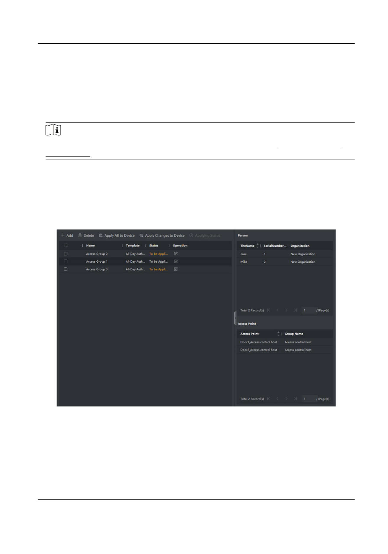
picture, linkage between card number and ngerprint, linkage between card number and
ngerprint, card password, card eecve period, etc).
1.
Click Access Control → Authorizaon → Access Group to enter the Access Group interface.
2.
Click Add to open the Add window.
3.
In the Name text eld, create a name for the access group as you want.
4.
Select a template for the access group.
Note
You should congure the template before access group sengs. Refer to Congure Schedule
and Template for details.
5.
In the le list of the Select Person eld, select person(s) to assign access authority.
6.
In the le list of the Select Access Point eld, select door(s), door staon(s) or oor(s) for the
selected persons to access.
7.
Click Save.
You can view the selected person(s) and the selected access point(s) on the right side of the
interface.
Figure 12-2 Display the Selected Person(s) and Access Point(s)
8.
Aer adding the access groups, you need to apply them to the access control device to take
eect.
1) Select the access group(s) to apply to the access control device.
2) Click Apply All to Devices start applying all the selected access group(s) to the access control
device or door staon.
DS-K3B631TX Series Swing Barrier User Manual
130
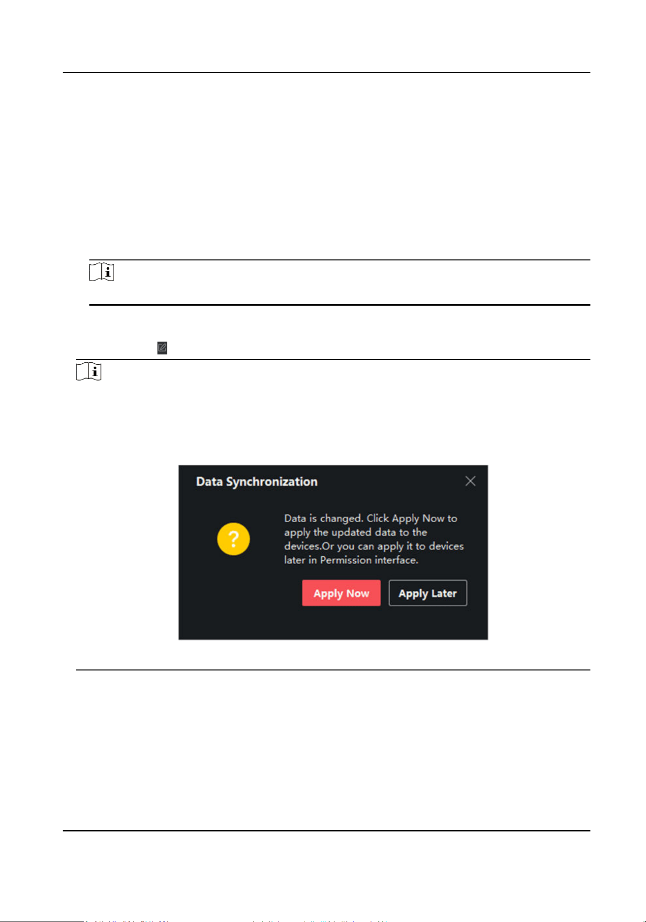
3) Click Apply All to Devices or Apply Changes to Devices.
Apply All to Devices
This operaon will clear all the existed access groups of the selected devices and then
apply the new access group to the device.
Apply Changes to Devices
This operaon will not clear the existed access groups of the selected devices and only
apply the changed part of the selected access group(s) to the device(s).
4) View the applying status in the Status column or click Applying Status to view all the applied
access group(s).
Note
You can check Display Failure Only to lter the applying results.
The selected persons in the applied access groups will have the authorizaon to enter/exit the
selected doors/door staons with their linked card(s) or ngerprints.
9.
Oponal: Click to edit the access group if necessary.
Note
If you change the persons' access informaon or other related informaon, you will view the
prompt Access Group to Be Applied on the right corner of the client.
You can click the prompt to apply the changed data to the device. You can select either Apply
Now or Apply Later.
Figure 12-3 Data Synchronizaon
12.7
Congure Advanced Funcons
You can congure the advanced funcons of access control to meet some special requirements in
dierent scene, such as mul-factor authencaon, an-passback, etc.
DS-K3B631TX Series Swing Barrier User Manual
131
Note
●
For the card related funcons(the type of access control card/mul-factor authencaon), only
the card(s) with access group applied will be listed when adding cards.
●
The advanced funcons should be supported by the device.
●
Hover the cursor on the Advanced
Funcon, and then Click to customize the advanced
funcon(s) to be displayed.
12.7.1 Congure Device Parameters
Aer adding the access control device, you can congure the parameters of access control device
(access controller), access control points (door or oor), alarm inputs, alarm outputs, card readers
and lane controller.
Congure
Parameters for Access Control Device
Aer adding the access control device, you can congure its parameters, including overlaying user
informaon on picture, uploading pictures aer capturing, saving captured pictures, etc.
Before You Start
Add access control device to the client.
Steps
1.
Click Access Control → Advanced
Funcon → Device Parameter .
Note
If you can not nd Device Parameter in the Advanced Funcon list, hover the cursor on the
Advanced Funcon, and then Click to select the Device Parameter to be displayed.
2.
Select an access device to show its parameters on the right page.
3.
Turn the switch to ON to enable the corresponding
funcons.
Note
●
The displayed parameters may vary for dierent access control devices.
●
Some of the following parameters are not listed in the Basic Informaon page, click More to
edit the parameters.
RS-485 Comm. Redundancy
You should enable this funcon if you wire the RS-485 card reader to the access control
device redundantly.
Display Detected Face
Display face picture when authencang.
Display Card Number
DS-K3B631TX Series Swing Barrier User Manual
132

Display the card informaon when authencang.
Display Person Informaon
Display the person informaon when authencang.
Overlay Person Info. on Picture
Display the person informaon on the captured picture.
Voice Prompt
If you enable this funcon, the voice prompt is enabled in the device. You can hear the voice
prompt when
operang in the device.
Upload Pic. Aer Linked Capture
Upload the pictures captured by linked camera to the system automacally.
Save Pic. Aer Linked Capture
If you enable this funcon, you can save the picture captured by linked camera to the device.
Press Key to Enter Card Number
If you enable this funcon, you can input the card No. by pressing the key.
Wi-Fi Probe
If you enable this funcon, the device can probe the surrounding communicaon devices'
MAC address and upload the MAC address to the system. If the MAC address match the
specied MAC address, the system can trigger some linkage acons.
3G/4G
If you enable this funcon, the device can communicate in 3G/4G network.
NFC An-Cloning
If you enable this funcon, you cannot use the cloned card for authencaon and further
enhance security.
4.
Click OK.
5.
Oponal: Click Copy to, and then select the access control device(s) to copy the parameters in
the page to the selected device(s).
Congure
Parameters for Door/Elevator
Aer adding the access control device, you can congure its access point (door or oor)
parameters.
Before You Start
Add access control device to the client.
Steps
1.
Click Access Control → Advanced Funcon → Device Parameter .
2.
Select an access control device on the le panel, and then click to show the doors or oors of
the selected device.
DS-K3B631TX Series Swing Barrier User Manual
133

3.
Select a door or oor to show its parameters on the right page.
4.
Edit the door or oor parameters.
Note
●
The displayed parameters may vary for dierent access control devices.
●
Some of the following parameters are not listed in the Basic Informaon page, click More to
edit the parameters.
Name
Edit the card reader name as desired.
Door Contact
You can set the door sensor as remaining closed or remaining open. Usually, it is remaining
closed.
Exit
Buon Type
You can set the exit buon as remaining closed or remaining open. Usually, it is remaining
open.
Door Locked Time
Aer swiping the normal card and relay acon, the mer for locking the door starts working.
Extended Open
Duraon
The door contact can be enabled with appropriate delay aer person with extended accesss
needs swipes her/his card.
Door Le Open Timeout Alarm
The alarm can be triggered if the door has not been closed in a congured me period. If it is
set as 0, no alarm will be triggered.
Lock Door when Door Closed
The door can be locked once it is closed even if the Door Locked Time is not reached.
Duress Code
The door can open by
inpung the duress code when there is duress. At the same me, the
client can report the duress event.
Super Password
The specic person can open the door by inpung the super password.
Dismiss Code
Create a dismiss code which can be used to stop the buzzer of the card reader (by entering
the dismiss code on the keypad).
DS-K3B631TX Series Swing Barrier User Manual
134
Note
●
The duress code, super code, and dismiss code should be dierent.
●
The duress code, super password, and the dismiss code should be dierent from the
authencaon password.
●
The length of duress code, super password, and the dismiss code is according the device,
usually it should contains 4 to 8 digits.
5.
Click OK.
6.
Oponal: Click Copy to , and then select the door/oor(s) to copy the parameters in the page to
the selected doors/oor(s).
Note
The door or oor's status duraon sengs will be copied to the selected door/oor(s) as well.
Congure Parameters for Card Reader
Aer adding the access control device, you can congure its card reader parameters.
Before You Start
Add access control device to the client.
Steps
1.
Click Access Control → Advanced Funcon → Device Parameter .
2.
In the device list on the
le, click to expand the door, select a card reader and you can edit the
card reader's parameters on the right.
3.
Edit the card reader basic parameters in the Basic Informaon page.
Note
●
The displayed parameters may vary for dierent access control devices. There are part of
parameters listed as follows. Refer to the user manual of the device for more details.
●
Some of the following parameters are not listed in the Basic Informaon page, click More to
edit the parameters.
Name
Edit the card reader name as desired.
OK LED Polarity/Error LED Polarity/Buzzer Polarity
Set OK LED Polarity/Error LED Polarity/Buzzer LED Polarity of main board according to the
card reader parameters. Generally, adopts the default sengs.
Minimum Card Swiping Interval
If the interval between card swiping of the same card is less than the set value, the card
swiping is invalid. You can set it as 0 to 255.
Max. Interval When Entering PWD
DS-K3B631TX Series Swing Barrier User Manual
135

When you inpung the password on the card reader, if the interval between pressing two
digits is larger than the set value, the digits you pressed before will be cleared automacally.
Alarm of Max. Failed Aempts
Enable to report alarm when the card reading aempts reach the set value.
Max. Times of Card Failure
Set the max. failure aempts of reading card.
Tampering Detecon
Enable the an-tamper detecon for the card reader.
Communicate with Controller Every
When the access control device cannot connect with the card reader for longer than the set
me, the card reader will turn oine automacally.
Buzzing Time
Set the card reader buzzing me. The available me ranges from 0 to 5,999s. 0 represents
connuous buzzing.
Card Reader Type/Card Reader Descripon
Get card reader type and descripon. They are read-only.
Fingerprint Recognion Level
Select the ngerprint recognion level in the drop-down list.
Default Card Reader Authencaon Mode
View the default card reader
authencaon mode.
Fingerprint Capacity
View the maximum number of available ngerprints.
Exisng Fingerprint Number
View the number of existed ngerprints in the device.
Score
The device will score the captured picture according to the yaw angle, pitch angle, and
pupillary distance. If the score is less than the congured value, face recognion will be failed.
Face Recognion Timeout Value
If the recognion me is more than the congured me, the device will remind you.
Face
Recognion Interval
The me interval between two connuous face recognions when authencang. By default,
it is 2s.
Face 1:1 Matching Threshold
Set the matching threshold when authencang via 1:1 matching mode. The larger the value,
the smaller the false accept rate and the larger the false rejecon rate when authencaon.
1:N Security Level
DS-K3B631TX Series Swing Barrier User Manual
136

Set the matching security level when authencang via 1:N matching mode. The larger the
value, the smaller the false accept rate and the larger the false rejecon rate when
authencaon.
Live Face Detecon
Enable or disable the live face detecon funcon. If enabling the funcon, the device can
recognize whether the person is a live one or not.
Live Face
Detecon Security Level
Aer enabling Live Face Detecon funcon, you can set the matching security level when
performing live face authencaon.
Max. Failed Aempts for Face Auth.
Set the maximum live face detecon failed aempts. The system will lock the user's face for 5
minutes if the live face
detecon is failed for more than the congured aempts. The same
user cannot authencate via the fake face within 5 minutes. Within the 5 minutes, the user
can authencate via the real face twice connuously to unlock.
Lock Authencaon Failed Face
Aer enabling the Live Face Detecon funcon, the system will lock the user's face for 5
minutes if the live face detecon is failed for more than the congured aempts. The same
user cannot
authencate via the fake face within 5 minutes. Within the 5 minutes, the user
can authencate via the real face twice connuously to unlock.
Applicaon Mode
You can select indoor or others applicaon modes according to actual environment.
4.
Click OK.
5.
Oponal: Click Copy to, and then select the card reader(s) to copy the parameters in the page to
the selected card reader(s).
Congure
Parameters for Alarm Output
Aer adding the access control device, if the device links to alarm outputs, you can congure the
parameters.
Before You Start
Add access control device to the client, and make sure the device supports alarm output.
Steps
1.
Click Access Control → Advanced
Funcon → Device Parameter to enter access control
parameter conguraon page.
2.
In the device list on the
le, click to expand the door, select an alarm input and you can edit
the alarm input's parameters on the right.
3.
Set the alarm output parameters.
Name
Edit the card reader name as desired.
DS-K3B631TX Series Swing Barrier User Manual
137

Alarm Output Acve Time
How long the alarm output will last aer triggered.
4.
Click OK.
5.
Oponal: Set the switch on the upper right corner to ON to trigger the alarm output.
Congure Parameters for Lane Controller
Aer adding the lane controller to the client, you can congure its parameters for passing through
the lane.
Before You Start
Add access control device to the client.
Steps
1.
Click Access Control → Advanced
Funcon → Device Parameter to enter Parameter Sengs
page.
2.
In the device list on the
le, select a lane controller and you can edit the lane controller's
parameters on the right.
3.
Edit the parameters.
Passing Mode
Select the controller which will control the barrier status of the device.
●
If you select According to Lane Controller's DIP
Sengs, the device will follow the lane
controller's DIP
sengs to control the barrier. The sengs on the soware will be invalid.
●
If you select According to Main Controller's Sengs, the device will follow the sengs of
the
soware to control the barrier. The DIP sengs of the lane controller will be invalid.
Free Passing Authencaon
If you enable this funcon, when both entrance and exit's barrier mode is Remain Open, the
pedestrians should authencate each me passing through the lane. Or an alarm will be
triggered.
Opening/Closing Barrier Speed
Set the barrier's opening and closing speed. You can select from 1 to 10. The greater the
value, the faster the speed.
Note
The recommended value is 6.
Audible Prompt Duraon
Set how long the audio will last, which is played when an alarm is triggered .
Note
0 refers to the alarm audio will be played unl the alarm is ended.
DS-K3B631TX Series Swing Barrier User Manual
138
Temperature Unit
Select the temperature unit that displayed in the device status.
4.
Click OK.
12.7.2 Congure Other Parameters
Aer adding the access control device, you can set its parameters such as network parameters,
capture parameters, RS-485 parameters, Wiegand parameters, etc.
Set Parameters for Face Recognion Terminal
For face recognion terminal, you can set its parameters including face picture database, QR code
authencaon, etc.
Steps
Note
This funcon should be supported by the device.
1.
Enter the Access Control module.
2.
On the
navigaon bar on the le, enter Advanced Funcon → More Parameters .
3.
Select an access control device in the device list and click Face Recognion Terminal.
4.
Set the parameters.
Note
These parameters displayed vary according to dierent device models.
COM
Select a COM port for conguraon. COM1 refers to the RS-485 interface and COM2 refers to
the RS-232 interface.
Face Picture Database
select Deep Learning as the face picture database.
Authencate by QR Code
If enabled, the device camera can scan the QR code to authencate. By default, the funcon
is disabled.
Blocklist Authencaon
If enabled, the device will compare the person who want to access with the persons in the
blocklist.
If matched (the person is in the blocklist), the access will be denied and the device will upload
an alarm to the client.
If mismatched (the person is not in the blocklist), the access will be granted.
DS-K3B631TX Series Swing Barrier User Manual
139

Save Authencang Face Picture
If enabled, the captured face picture when authencang will be saved on the device.
MCU Version
View the device MCU version.
5.
Click Save.
Set RS-485 Parameters
You can set the access control device's RS-485 parameters including the baud rate, data bit, the
stop bit, parity type,
ow control type, communicaon mode, work mode, and connecon mode.
Before You Start
Add access control device to the client, and make sure the device supports RS-485 interface.
Steps
1.
Enter the Access Control module.
2.
On the
navigaon bar on the le, enter Advanced Funcon → More Parameters .
3.
Select an access control device in the device list and click RS-485 to enter the RS-485 Sengs
page.
4.
Select the serial port number from the drop-down list to set the RS-485 parameters.
5.
Set the baud rate, data bit, the stop bit, parity type,
communicaon mode, working mode, and
connecon mode in the drop-down list.
Note
When the connecon mode is Connect Access Control Device, you can select Card No. or
Person ID as the output type.
6.
Click Save.
●
The congured parameters will be applied to the device automacally.
●
When you change the working mode or connecon mode, the device will reboot
automacally.
Set Wiegand Parameters
You can set the access control device's Wiegand channel and the communicaon mode. Aer
seng the Wiegand parameters, the device can connect to Wiegand card reader via Wiegand
communicaon.
Before You Start
Add access control device to the client, and make sure the device supports Wiegand.
Steps
1.
Enter the Access Control module.
2.
On the
navigaon bar on the le, enter Advanced Funcon → More Parameters .
DS-K3B631TX Series Swing Barrier User Manual
140
3.
Select an access control device in the device list and click Wiegand to enter the Wiegand
Sengs page.
4.
Set the switch to on to enable the Wiegand funcon for the device.
5.
Select the Wiegand channel No. and the
communicaon mode from the drop-down list.
Note
If you set Communicaon Direcon as Sending, you are required to set the Wiegand Mode as
Wiegand 26 or Wiegand 34.
6.
Click Save.
●
The
congured parameters will be applied to the device automacally.
●
Aer changing the communicaon direcon, the device will reboot automacally.
Enable M1 Card
Encrypon
M1 card encrypon can improve the security level of authencaon.
Steps
Note
The funcon should be supported by the access control device and the card reader.
1.
Enter the Access Control module.
2.
On the
navigaon bar on the le, enter Advanced Funcon → More Parameters .
3.
Select an access control device in the device list and click M1 Card Encrypon to enter the M1
Card Encrypon page.
4.
Set the switch to on to enable the M1 card
encrypon funcon.
5.
Set the sector ID.
The sector ID ranges from 1 to 100.
6.
Click Save to save the
sengs.
12.8 Door/Elevator Control
In Monitoring module, you can view the real-me status of the doors or elevators managed by the
added access control device. You can also control the doors and elevators such as open/close the
door, or remain the door open/closed via the client remotely. The
real-me access event are
displayed in this module. You can view the access details and person details.
Note
For the user with door/elevator control permission, the user can enter the Monitoring module and
control the door/elevator. Or the icons used for control will not show. For seng the user
permission, refer to .
DS-K3B631TX Series Swing Barrier User Manual
141
12.8.1 Control Door Status
You can control the status for the door(s), including unlock door, locking door, remaining the door
unlock, remaining the door locked, remain all unlocked, etc.
Before You Start
●
Add person and assign access authorizaon to designed person, and person will have the access
authorizaon to the access points (doors). For details, refer to Person Management and Set
Access Group to Assign Access Authorizaon to Persons .
●
Make sure the
operaon user has the permission of the access points (doors). For details, refer
to .
Steps
1.
Click Monitoring to enter the status monitoring page.
2.
Select an access point group on the upper-right corner.
Note
For managing the access point group, refer to Group Management .
The doors in the selected access control group will display.
3.
Click a door icon to select a door, or press Ctrl and select mulple doors.
Note
For Remain All Unlocked and Remain All Locked, ignore this step.
4.
Click the following buons to control the door.
Unlock
When the door is locked, unlock it and it will be open for once. Aer the open duraon, the
door will be closed and locked again
automacally.
Lock
When the door is unlocked, lock it and it will be closed. The person who has the access
authorizaon can access the door with credenals.
Remain Unlocked
The door will be unlocked (no maer closed or open). All the persons can access the door
with no
credenals required.
Remain Locked
The door will be closed and locked. No person can access the door even if he/she has the
authorized credenals, except the super users.
Remain All Unlocked
All doors in the group will be unlocked (no maer closed or open). All the persons can access
the doors with no credenals required.
Remain All Locked
DS-K3B631TX Series Swing Barrier User Manual
142
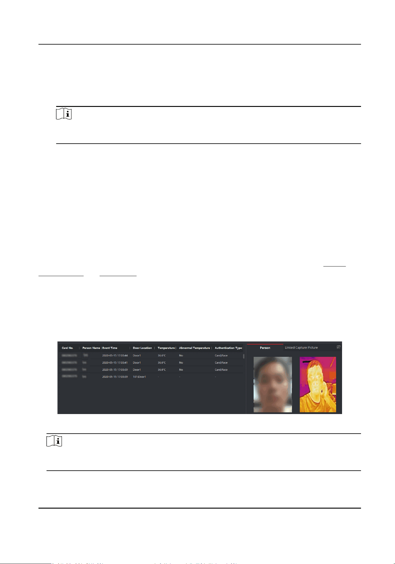
All doors in the group will be closed and locked. No person can access the doors even if
he/she has the authorized credenals, except the super users.
Capture
Capture a picture manually.
Note
The Capture buon is available when the device supports capture funcon. The picture is
saved in the PC running the client. For seng the saving path, refer to .
Result
The icon of the doors will change in real-me according to the operaon if the operaon is
succeeded.
12.8.2 Check Real-Time Access Records
The real-me access records can be displayed in the client, including card swiping records, face
recognion records, skin-surface temperature informaon, etc. Also, you can view the person
informaon and view the picture captured during access.
Before You Start
You have added person(s) and access control device(s) to the client. For details, refer to Person
Management and Add Device .
Steps
1.
Click Monitoring to enter monitoring module.
Real-me access records are displayed on the boom of the page. You can view record details,
including card No., person name, event me, door locaon, temperature, authencaon type
etc.
Figure 12-4
Real-me Access Records
Note
You can right click the column name of access event table to show or hide the column according
to actual needs.
DS-K3B631TX Series Swing Barrier User Manual
143
2.
Oponal: Select an access point group from the drop-down list in the upper-right corner to
show the real me access records of the selected group.
3.
Oponal: Check the event type and event status.
The detected events of checked type and status will be displayed in the list below.
4.
Oponal: Check Show Latest Event to view the latest access record.
The record list will be listed reverse chronologically.
5.
Oponal: Check Enable Abnormal Temperature Prompt to enable abnormal skin-surface
temperature prompt.
Note
When enabled, if there is abnormal temperature informaon, an Abnormal Temperature
window pops up when you enter Monitoring module, displaying person's picture, skin-surface
temperature, card No., person name, etc.
6.
Oponal: Click an event to view person pictures (including captured picture and prole).
Note
In Linked Capture Picture eld, you can double click the captured picture to view an enlarged
picture.
7.
Oponal: Click to view monitoring details (including person's detailed informaon and the
captured picture).
Note
In the pop-up window, you can click to view monitoring details in full screen.
DS-K3B631TX Series Swing Barrier User Manual
144
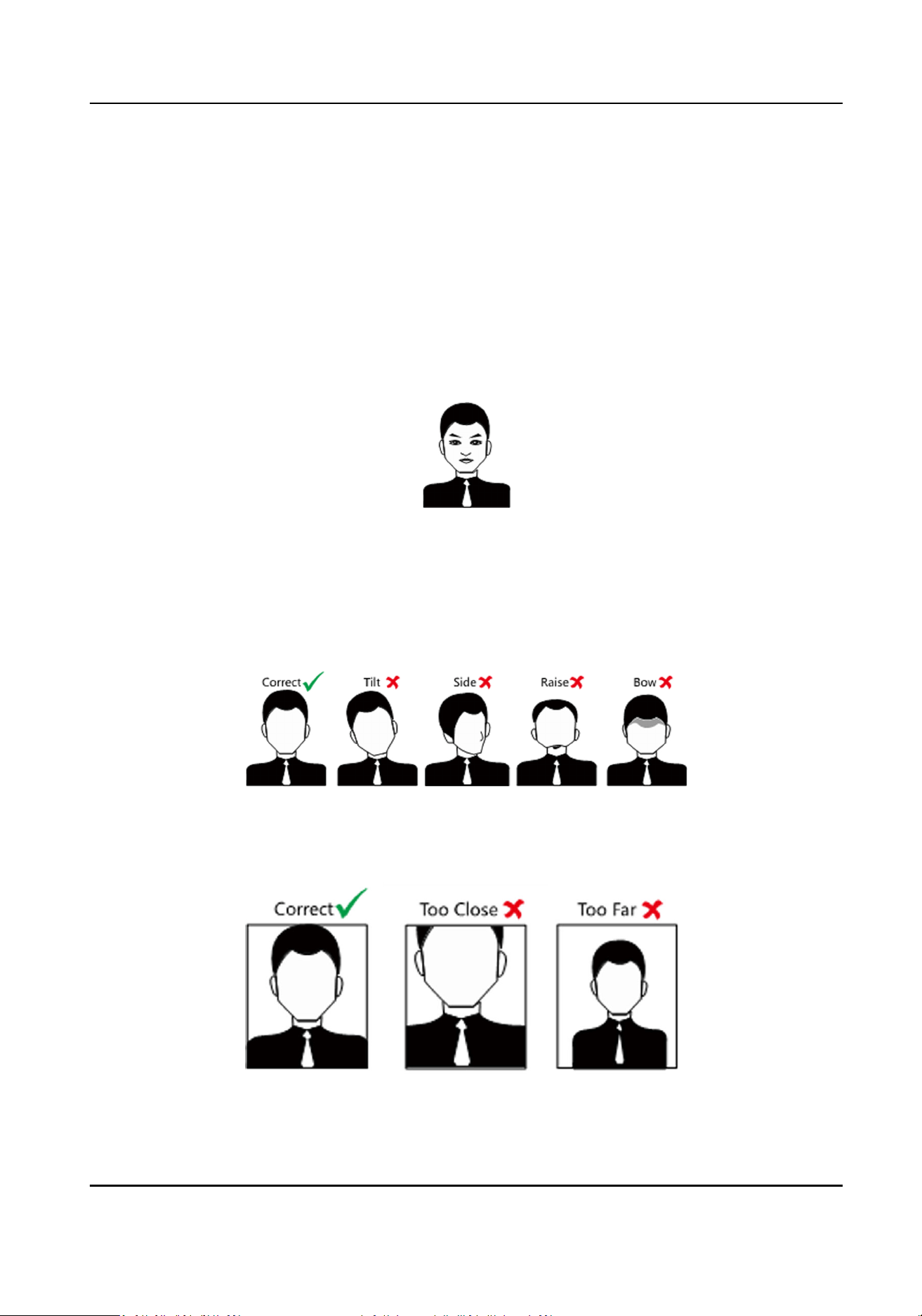
Appendix A. Tips When Collecng/Comparing Face
Picture
The
posion when collecng or comparing face picture is as below:
Expression
●
Keep your expression naturally when collecng or comparing face pictures, just like the
expression in the picture below.
●
Do not wear hat, sunglasses, or other accessories that can aect the facial recognion funcon.
●
Do not make your hair cover your eyes, ears, etc. and heavy makeup is not allowed.
Posture
In order to get a good quality and accurate face picture, posion your face looking at the camera
when collecng or comparing face pictures.
Size
Make sure your face is in the middle of the collecng window.
DS-K3B631TX Series Swing Barrier User Manual
145

Appendix B. DIP Switch
B.1 DIP Switch Descripon
The DIP switch is on the main user extended interface board. No.1 to No 4 is from the low bit to
the high bit.
Figure B-1 DIP Switch
When the switch is towards ON, it means the switch is enabled, otherwise, the switch is o.
B.2 DIP Switch Corresponded
Funcons
Note
Aer seng the DIP switch, you should reboot the device, or the funcon cannot take eect.
The 4-bit DIP switch corresponded funcons on the access control board are as follows:
DS-K3B631TX Series Swing Barrier User Manual
146
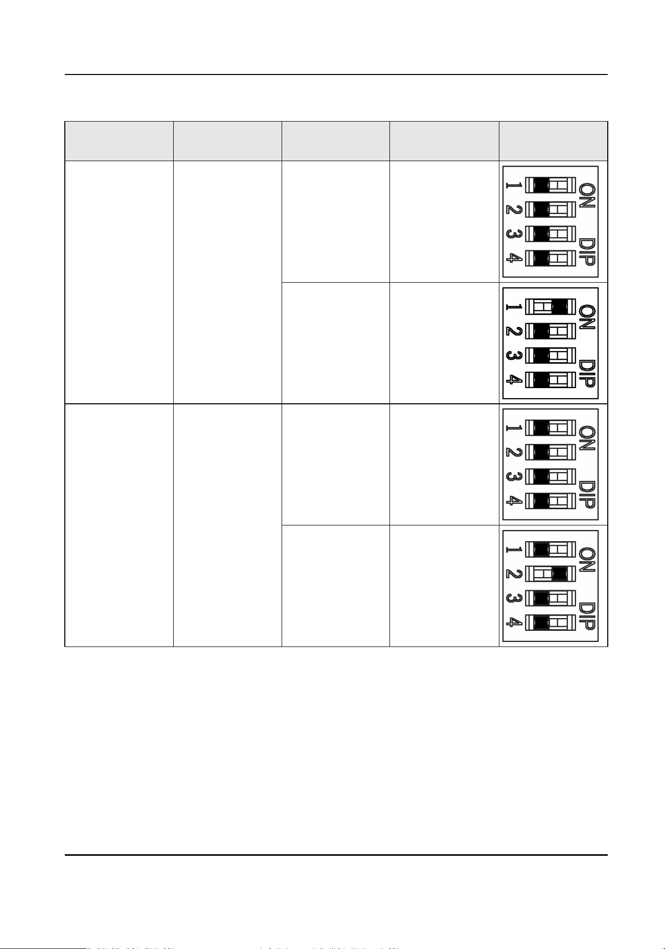
Bit Device Mode Funcon Decimal Value DIP Switch
Address Diagram
1 Work Mode Normal Mode 0
Study Mode 1
2 Keyfob Paring
Mode
Disable Keyfob
Paring Mode
0
Enable Keyfob
Paring Mode
1
B.3 Side Light Board DIP Switch Descripon
Congure the DIP switch address of side light.
DS-K3B631TX Series Swing Barrier User Manual
147
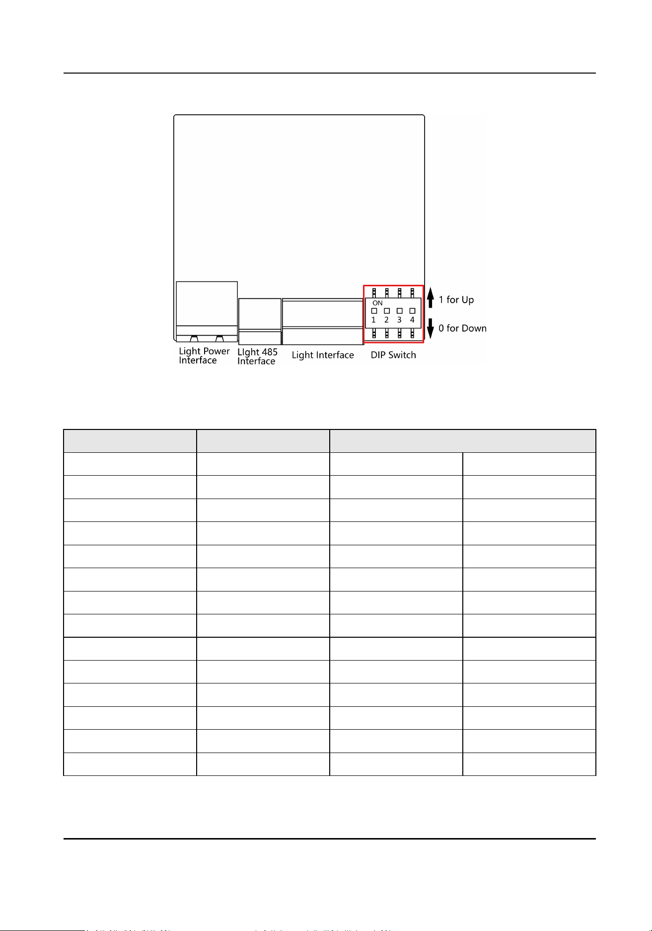
Figure B-2 Side Light Board DIP Switch
Table B-1 Light Board DIP Switch Descripon
Posion Address Value (Start from Le)
0 65 0 0000
1 81 1 1000
2 97 10 0100
3 113 11 1100
4 129 100 0010
5 130 101 1010
6 131 110 0110
7 132 111 1110
8 133 1000 0001
9 134 1001 1001
10 135 1010 0101
11 136 1011 1101
12 137 1100 0011
13 138 1101 1011
DS-K3B631TX Series Swing Barrier User Manual
148
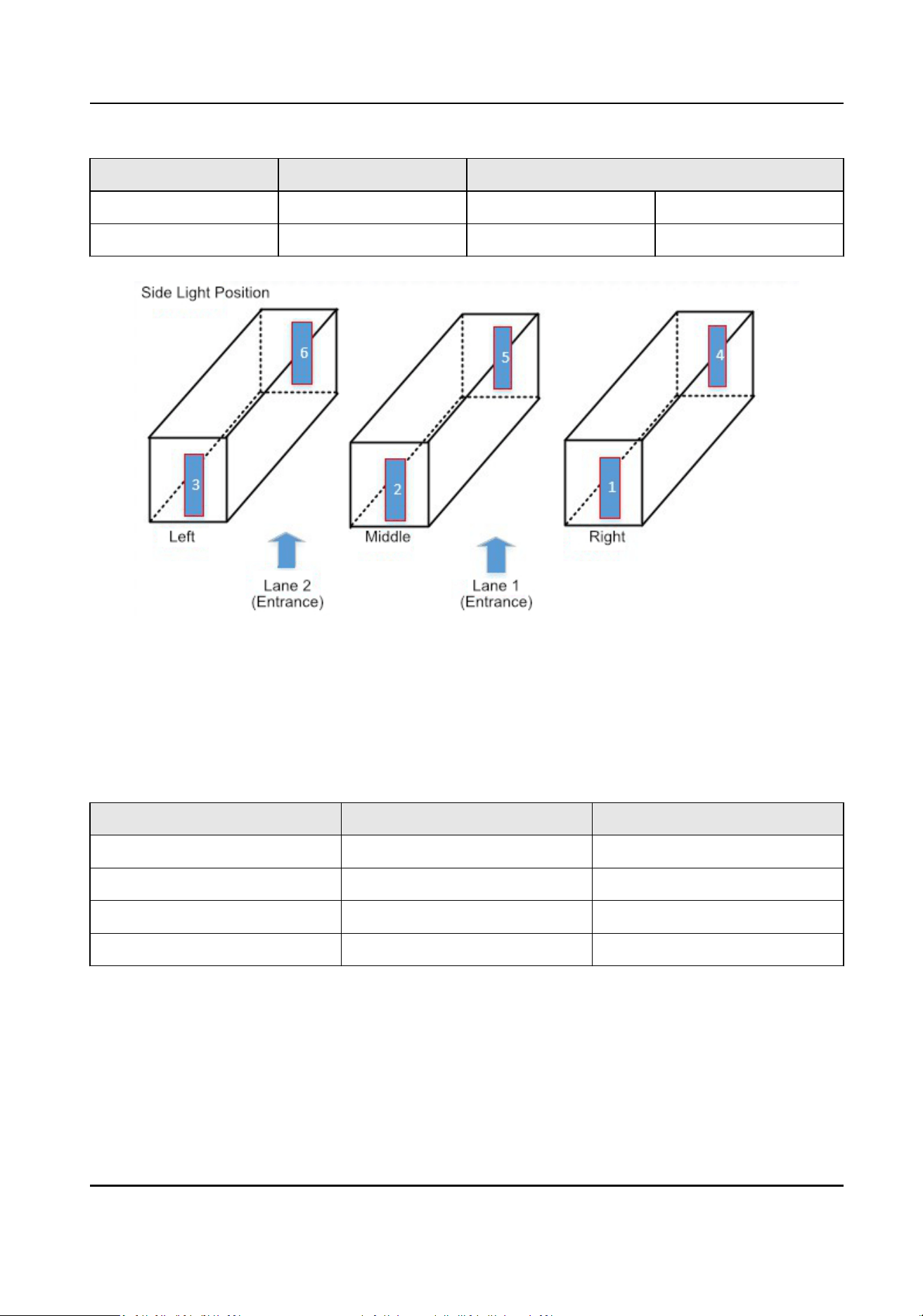
Posion Address Value (Start from Le)
14 139 1110 0111
15 140 1111 1111
Figure B-3 Side Light Posion
Single-Lane Scenario
In single-lane scenario, the side lights are located at the posion of NO. 1, 3, 4, 6. Side light No. 1 is
near the main user extended interface board.
Table B-2 Single-Lane DIP Switch
Descripon
Posion Address Value
No. 1 65 0000
No. 3 113 1100
No. 4 81 1000
No. 6 97 0100
DS-K3B631TX Series Swing Barrier User Manual
149

Dual-Lane Scenario
Table B-3 Dual-Lane DIP Switch Descripon
Posion Address Value
No. 1 65 0000
No. 2 65 0000
No. 3 113 1100
No. 4 81 1000
No. 5 97 0100
No. 6 97 0100
DS-K3B631TX Series Swing Barrier User Manual
150

Appendix C. Event and Alarm Type
Event Alarm Type
Tailgang Visual and Audible
Reverse Passing Visual and Audible
Force Accessing None
Climb over Barrier Visual and Audible
Overstay Visual and Audible
Passing Timeout None
Intrusion Visual and Audible
Barrier Obstructed None
DS-K3B631TX Series Swing Barrier User Manual
151

Appendix D. Error Code Descripon
The swing barrier will display the error code on the seven-segment display if error occurred. Refer
to the table below to
nd the descripon of each number.
Error Reason Code Error Reason Code
Normal Working 00 Lower Fih IR Beam Triggered 21
First IR Beam Triggered 01 Lower Sixth IR Beam Triggered 22
Second IR Beam Triggered 02 Lower Seventh IR Beam
Triggered
23
Third IR Beam Triggered 03 Lower Eighth IR Beam
Triggered
24
Fourth IR Beam Triggered 04 Lower Ninth IR Beam Triggered 25
Fih IR Beam Triggered 05 Lower Tenth IR Beam Triggered 26
Sixth IR Beam Triggered 06 Lower Eleventh IR Beam
Triggered
27
Seventh IR Beam Triggered 07 Lower Twelh IR Beam
Triggered
28
Eighth IR Beam Triggered 08 Lower Thirteenth IR Beam
Triggered
29
Ninth IR Beam Triggered 09 Lower Fourteenth IR Beam
Triggered
30
IR Beam Triggered 10 Lower Fieenth IR Beam
Triggered
31
Eleventh IR Beam Triggered 11 Lower Sixteenth IR Beam
Triggered
32
Twelh IR Beam Triggered 12 Light Board Oine (Entrance) 49
Thirteenth IR Beam Triggered 13 Light Board Oine (Exit) 50
Fourteenth IR Beam Triggered 14 IR Adapter Oine (Up) 51
Fieenth IR Beam Triggered 15 IR Adapter Oine (Low) 52
Sixteenth IR Beam Triggered 16 CAN Bus Excepon 53
Lower First IR Beam Triggered 17 Not Studying 54
DS-K3B631TX Series Swing Barrier User Manual
152

Error Reason Code Error Reason Code
Lower Second IR Beam
Triggered
18 Obstrucon 55
Lower Third IR Beam Triggered 19 Exceeding Studying Range 56
Lower Fourth IR Beam
Triggered
20 Motor Excepon 57
DS-K3B631TX Series Swing Barrier User Manual
153
Appendix E. Communicaon Matrix and Device
Command
Communicaon Matrix
Scan the following QR code to get the device communicaon matrix.
Note that the matrix contains all
communicaon ports of Hikvision access control and video
intercom devices.
Figure E-1 QR Code of Communicaon Matrix
Device Command
Scan the following QR code to get the device common serial port commands.
Note that the command list contains all commonly used serial ports commands for all Hikvision
access control and video intercom devices.
Figure E-2 Device Command
DS-K3B631TX Series Swing Barrier User Manual
154

UD30186B-B