Loading ...
Loading ...
Loading ...
15” TRUE ICE
®
MACHINE INSTALL GUIDE
TEC_TM_155 | REV. D | EN 09/23/2022
Page 25 of 66
PRIOR TO INSTALLATION
DRAIN LINE INSTALLATION
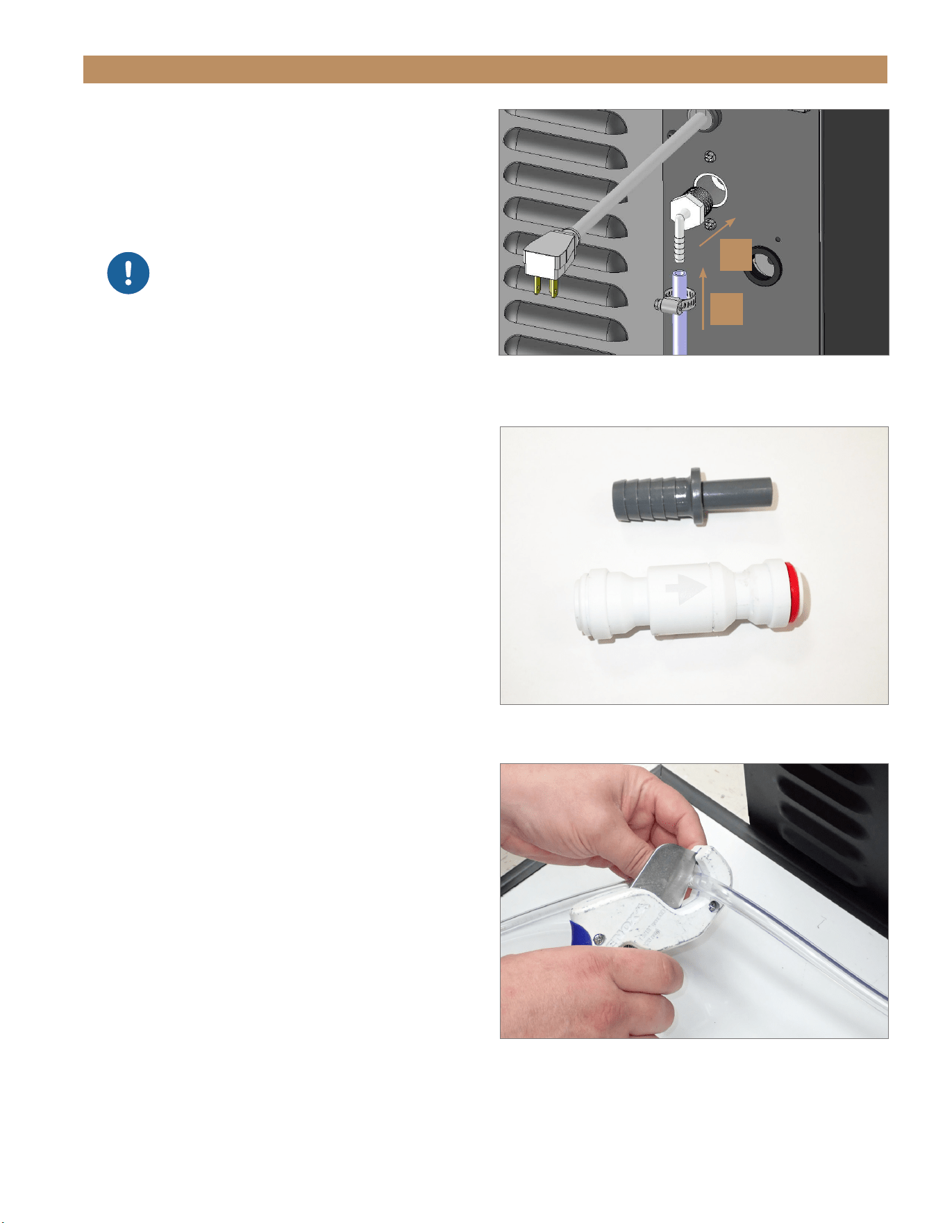
1. Thread the 1/2” NPT connector into the drain
fitting. See fig. 1.
NOTE: THREAD SEALANT REQUIRED AND TO
BE SUPPLIED BY INSTALLER.
2. With the clamp on the hose, connect the clear
drain hose to the barbed fitting. See fig. 1.
3. Tighten the hose clamp.
NOTE: VERIFY THE ICE MACHINE DRAINS
THROUGH TWO CYCLES WITHOUT ANY DRAIN
ALARM DURING INSTALLATION.
For more information, see “Drain Time Alarm"
(page 40).
CHECK VALVE INSTALLATION (REQUIRED)
1. Locate the provided check valve components. See
fig. 2.
2. With tubing cutters, cut the drain line near the
connection point. See fig. 3.
3. With the water flow arrow (see fig. 4) pointing away
from the ice machine, connect the cut drain line
to the check valve. See fig. 5. Use the provided
adapter if needed.
4. Check the drain system for leaks.
FIG. 1.
Be sure to tightly clamp the drain line onto the barbed fitting.
Thread sealant required.
FIG. 2.
Check valve and adapter shipped inside the ice machine.
FIG. 3.
Cut the drain line with tubing cutters.
1
2
NOTICE: DO NOT OVERTIGHTEN THE
NPT CONNECTOR!
DO NOT TORQUE THE CONNECTOR MORE
THAT 50 IN-LB (5.65 NM). THIS MAY
CAUSE THE FITTING TO CRACK. CHECK
THE DRAIN FITTING FOR LEAKS BEFORE
COMPLETING THE INSTALLATION.
Loading ...
Loading ...
Loading ...