Loading ...
Loading ...
Loading ...
14
NOTE:
These conversions should only be carried out
by qualified persons. All connections must be
checked for leaks before re-commissioning the
appliance.
Adjustment of components that have
adjustments / settings sealed (e.g. paint
sealed) can only be adjusted in accordance
with the following instructions and shall be
re-sealed before re-commissioning this
appliance.
For all relevant gas specifications refer to the
Gas Specifications table at the end of this
section.
1. Remove the following:-
Gas control knobs.
Control Panel.
Chargrill castings / griddle plates and inner
radiants.
Main burners.
2. Remove main burner injectors and replace with
correct size injectors as shown in ‘Gas
Specifications Tables’ at rear of this section.
3. Check / adjust main burner aeration shutter as
shown in ‘Gas Specifications Tables’ at rear of
this section.
4. Refit the following:-
Main burners.
Inner radiants, chargrill castings / griddle
plates.
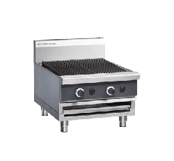
1. Disconnect the following:-
Gas supply tube to pilot burner.
2. Remove pilot injectors and replace with correct
size pilot injectors as shown in ‘Gas
Specifications Tables’ at rear of this section.
3. Re-connect the following:-
Gas supply tube to pilot burner.
Inner radiants, chargrill castings / griddle
plates.
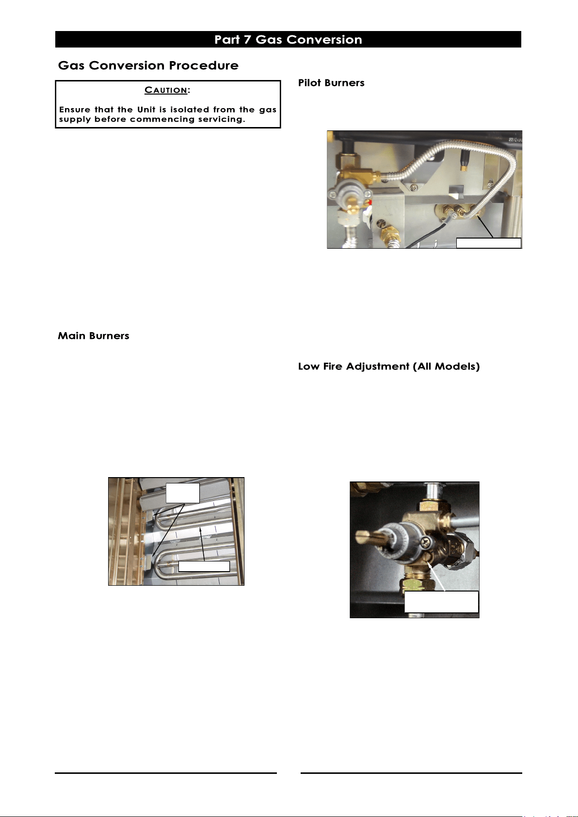
1. Light main burners and check flame size on
‘Low’ setting.
Adjust low fire adjustment screw on burner
gas control valves by screwing adjustment
screw fully ‘In’ and then unscrewing by the
measurement shown in ‘Gas Specifications’
table at the rear of this Section, to obtain the
desired flame size.
NOTE:
‘Low Fire Adjustment Screw’ should be sealed with
coloured paint on completion of low fire
adjustment.
2. Refit control panel.
3. Refit gas control knobs.
Main Burner
Shell
Brackets
Low Fire
Adjustment Screw
Gas Supply Tube
Loading ...
Loading ...
Loading ...