⑧
ADCEL
AD410 Pro
USER'S MANUAL
ANEEL
AD418Pre
OBOI
IM
BAT
omi
Lookup
Rewew
Satup
OBDII+BATTERY TESTER
ENTER
1/M]
EXII

UK
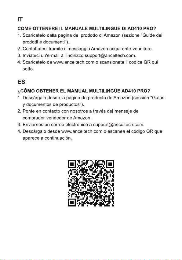
HOW TO GET THE AD410 PRO MULTILINGUAL MAMUAL?
1.Download it from Amazon product page("Product guides and
documents" section).
2. Contact us via Amazon buyer-seller message.
3.Send us an email at support@anceltech.com.
4.Download it from www.anceltech.com or scan the QR code below.
DE
WIE ERHALTE ICH DAS MEHRSPRACHIGE HANDBUCH DES
AD410 PRO?
1.Laden Sie es von der Amazon-Produktseite herunter (Abschnitt
"Produktleitfaden und Dokumente").
2.Kontaktieren Sie uns über eine Amazon-Kaufer-Verkaufer-Nachricht.
3.Senden Sie uns eine E-Mail an support@anceltech.com.
4.Laden Sie es von www.anceltech.com herunter oder scannen Sie
den QR-Code unten.
FR
COMMENT OBTENIR LE MANUEL MULTILINGUE DE L'AD410 PRO ?
1.Teléchargez-le à partir de la page du produit Amazon (section
"Guides produits et documents").
2. Contactez-nous via le message acheteur-vendeur d'Amazon.
3.Envoyez-nous un courrier électronique à l'adresse
support@anceltech.com.
4.Télechargez-le sur www.anceltech.com ou scannez le code QR
ci-dessous.
IT
COME OTTENERE IL MANUALE MULTILINGUE DI AD410 PRO?
1.Scaricatelo dalla pagina del prodotto di Amazon(sezione "Guide dei
prodotti e documenti").
2. Contattateci tramite il messaggio Amazon acquirente-venditore.
3.Inviateci un'e-mail all'indirizzo support@anceltech.com.
4.Scaricatelo da www.anceltech.com o scansionate il codice QR qui
sotto.
ES
LCOMO OBTENER EL MAMUAL MULTILINGUE AD410 PRO?
1.Descargalo desde la pagina de producto de Amazon(seccion "Guias
y documentos de productos").
2. Ponte en contacto con nosotros a traves del mensaje de
comprador-vendedor de Amazon.
3.Enviarnos un correo electrónico a support@anceltech.com.
4. Descargalo desde www.anceltech.com o escanea el codigo QR que
aparece a continuacion.
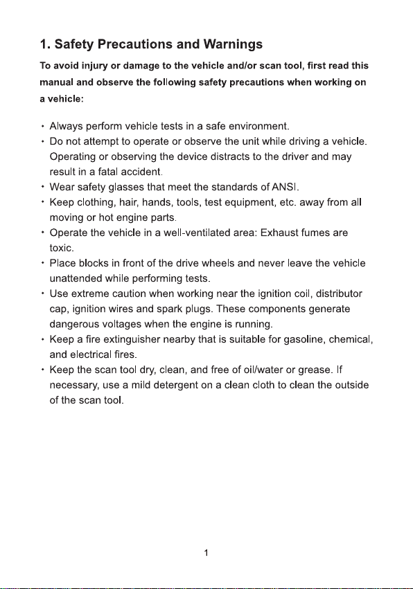
1.Safety Precautions and Warnings
To avoid injury or damage to the vehicle and/or scan tool, first read this
manual and observe the following safety precautions when working on
a vehicle:
·Always perform vehicle tests in a safe environment.
· Do not attempt to operate or observe the unit while driving a vehicle.
Operating or observing the device distracts to the driver and may
result in a fatal accident.
· Wear safety glasses that meet the standards of ANSl.
·Keep clothing, hair, hands, tools, test equipment, etc. away from all
moving or hot engine parts.
· Operate the vehicle in a well-ventilated area:Exhaust fumes are
toxic.
· Place blocks in front of the drive wheels and never leave the vehicle
unattended while performing tests.
·Use extreme caution when working near the ignition coil, distributor
cap, ignition wires and spark plugs. These components generate
dangerous voltages when the engine is running.
· Keep a fire extinguisher nearby that is suitable for gasoline, chemical,
and electrical fires.
·Keep the scan tool dry, clean, and free of oil/water or grease.If
necessary, use a mild detergent on a clean cloth to clean the outside
of the scan tool.
1
2.General Information
2.1 On-Board Diagnostics(OBD)Ⅱ
The first generation of on-board diagnostics (called OBD I) was
developed by the California Air Resources Board (CARB) and
introduced in 1988 to monitor some components of vehicle emission
control. With the advancement of technology and the desire to improve
the on-board diagnostic system, a new generation of on-board
diagnostic system was developed. This second generation on-board
diagnostic system is called "OBD II".
The OBD II system is designed to monitor emission control systems
and major engine components by performing either continuous or
periodic tests of specific components and vehicle conditions. When a
problem is detected, the OBD lI system turns on a warning light (MIL)
on the vehicle's instrument panel to alert the driver, typically with the
words "Check Engine" or "Service Engine Soon." The system also
stores important information about the detected malfunction so a
technician can accurately find and fix the problem. Below are three
such valuable pieces of information:
1)Whether the malfunction indicator lamp (MIL)is set to 'On' or 'Off;
2)Whether diagnostic trouble codes(DTCs) are stored and if so,
which ones;
3)Status of the standby monitor.
2.2 Diagnostic Trouble Codes (DTCs)
OBD lI Diagnostic Trouble Codes are codes stored by the on-board
computer diagnostic system in response to a problem detected in the
vehicle. These codes identify a specific problem area and are intended
to give you an indication of where in the vehicle a fault may be
occurring. OBD II Diagnostic Trouble Codes consist of a five-character
alphanumeric code.The first character, a letter, indicates which control
2
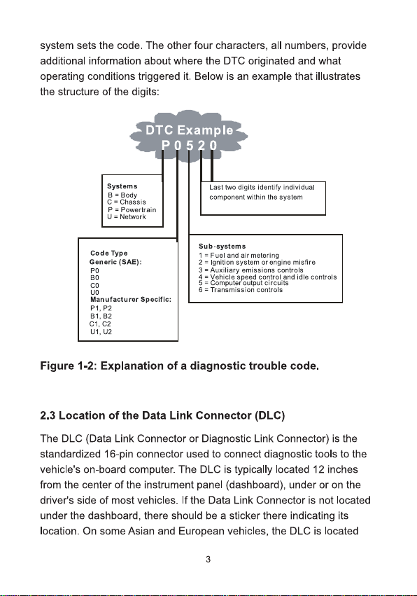
system sets the code. The other four characters, all numbers, provide
additional information about where the DTC originated and what
operating conditions triggered it. Below is an example that illustrates
the structure of the digits:
DTC Example
0520
Systems
B = Body
C=Chassis
P=Powertrain
U=Network
Last two digits ldentify individual
component within the system
Sub-systems
Code Type
1=Fuel and air metering
2=Ignition system orengine misfire
3=Auxiliary emissions controls
4 = Vehicle speed control and idle controls
5= Computer output circuits
6 = Transmission controls
Generic (SAE):
P0
B0
C0
UO
Manufacturer Specific:
P1,P2
B1.B2
C1,C2
U1,U2
Figure 1-2: Explanation of a diagnostic trouble code.
2.3 Location of the Data Link Connector (DLC)
The DLC(Data Link Connector or Diagnostic Link Connector) is the
standardized 16-pin connector used to connect diagnostic tools to the
vehicle's on-board computer. The DLC is typically located 12 inches
from the center of the instrument panel(dashboard), under or on the
driver's side of most vehicles. If the Data Link Connector is not located
under the dashboard, there should be a sticker there indicating its
location. On some Asian and European vehicles, the DLC is located
3
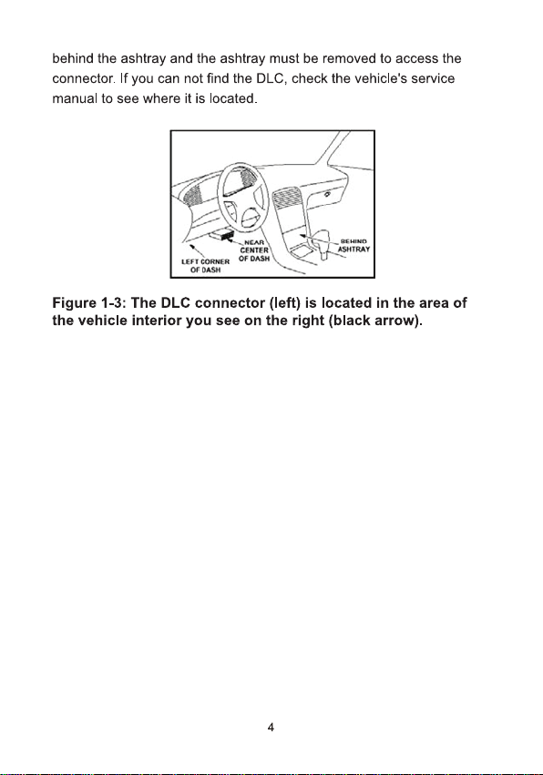
behind the ashtray and the ashtray must be removed to access the
connector.If you can not find the DLC, check the vehicle's service
manual to see where it is located.
LFTEEB
005458
A)
1
0+0*8#
0
ASMAT
Figure 1-3:The DLC connector (left) is located in the area of
the vehicle interior you see on the right (black arrow).
4
3.Using the Scan Tool
3.1 Tool Description -ANCEL AD410 Pro
7
1
O/0
A?416Pe
OBDll
M
BAT
)
Lockup
Review
Seup
OBDII+BATTERY TESTER
4-
2-
3
[/M
ENTER
EXIT
5
6-
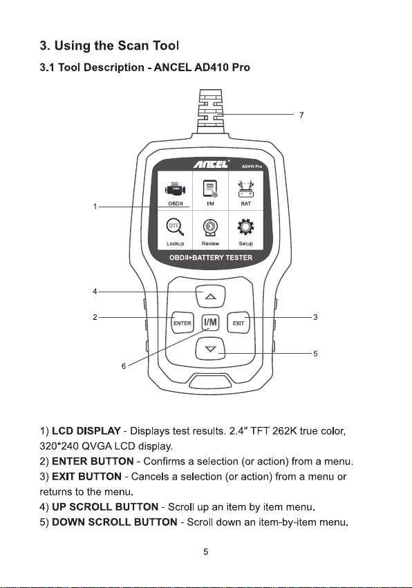
1) LCD DISPLAY -Displays test results.2.4"TFT 262K true color,
320*240 QVGA LCD display.
2) ENTER BUTTON -Confirms a selection (or action) from a menu.
3) EXIT BUTTON -Cancels a selection (or action) from a menu or
returns to the menu.
4) UP SCROLL BUTTON -Scroll up an item by item menu.
5) DOWN SCROLL BUTTON-Scroll down an item-by-item menu.
5
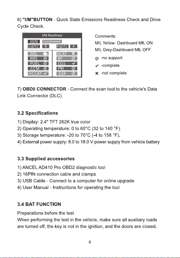
6)"I/M"BUTTON-Quick State Emissions Readiness Check and Drive
Cycle Check.
IGN
CTDTO
1/M Readiness
compression
6
PdD
4
MI
MIS
FUEL
CCM
HCCAT √
NCAT
BP
EGS
PM
EGR
×
Comments:
MIL Yellow- Dashboard MIL ON
MIL Grey-Dashboard MIL OFF
-no support
√-complete
×-not complete
7)OBDII CONNECTOR -Connect the scan tool to the vehicle's Data
Link Connector (DLC)
3.2 Specifications
1)Display:2.4"TFT 262K true color
2)Operating temperature:0 to 60℃(32 to 140°F).
3)Storage temperature:-20 to 70℃(-4 to 158°F).
4) External power supply: 8.0 to 18.0 V power supply from vehide battery
3.3 Supplied accessories
1)ANCELAD410 Pro OBD2 diagnostic tool
2) 16PIN connection cable and clamps
3)USB Cable- Connect to a computer for online upgrade
4) User Manual- Instructions for operating the tool
3.4 BAT FUNCTION
Preparations before the test
When performing the test in the vehicle, make sure all auxiliary loads
are turned off, the key is not in the ignition, and the doors are closed.
6
Connecting the tester
1)Connect the red clamp to the positive (+)terminal and the black
clamp to the negative(-) terminal.
2)To make a proper connection, move the clamps back and forth. The
tester requires that both sides of each clamp be firmly connected
before testing. If the connection is poor, a CHECK CONNECTION OR
WIGGLE CLAMPS message will appear, clean the clamps and
reconnect the clamps.
3)The preferred test position is at the battery terminals. If the battery is
not accessible, you can also perform the test at the jumper terminal;
however, the measured available power may be lower than the actual
value.
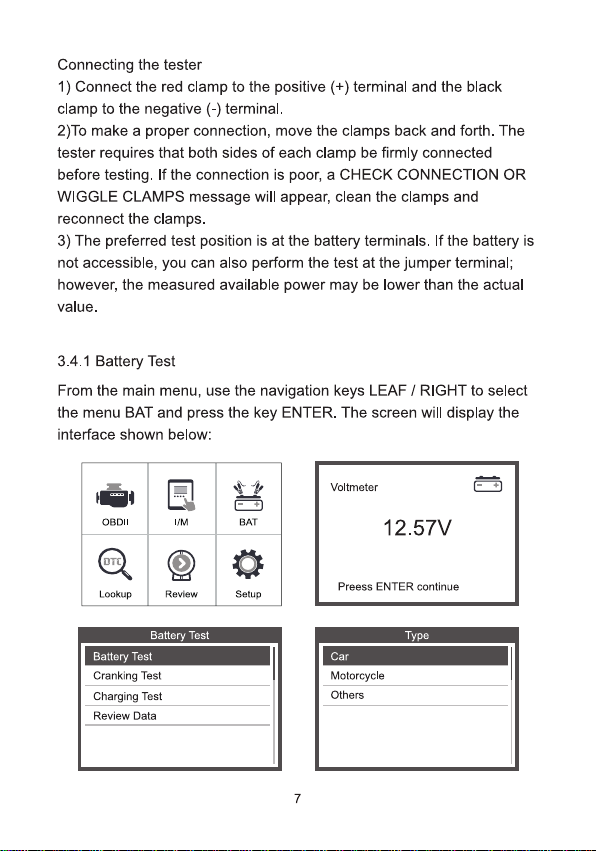
3.4.1 Battery Test
From the main menu, use the navigation keys LEAF /RIGHT to select
the menu BAT and press the key ENTER. The screen will display the
interface shown below:
OBDlI
I/M
BAT
OT0)
Lookup
Review
Setup
Voltmeter
12.57V
Preess ENTER continue
Battery Test
Battery Test
Cranking Test
Charging Test
Review Data
Type
Car
Motorcycle
Others
7
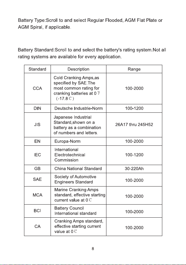
Battery Type:Scroll to and select Regular Flooded, AGM Flat Plate or
AGM Spiral, if applicable.
Battery Standard:Scroll to and select the battery's rating system.Not all
rating systems are available for every application.
Standard
Description
Range
CCA
Cold Cranking Amps,as
specified by SAE.The
most common rating for
cranking batteries at OF
(-17.8C)
100-2000
DIN
Deutsche Industrie-Norm
100-1200
JIS
Japanese Industrial
Standard,shown on a
battery as a combination
of numbers and letters.
26A17 thru 245H52
EN
Europa-Norm
100-2000
IEC
International
Electrotechnical
Commission
100-1200
GB
China National Standard
30-220Ah
SAE
Society of Automotive
Engineers Standard
100-2000
MCA
Marine Cranking Amps
standard,effective starting
current value at 0C
100-2000
BCl
Battery Council
International standard
100-2000
CA
Cranking Amps standard,
effective starting current
value at 0C
100-2000
8
Battery Test
Regular Flooded
AGM Flat Plate
AGM Spiral
GEL
EFB
CCA
EN
Select Input
SAE
CA
DIN
JIS
Setting Rate
500A CCA
[▲Nw]:Adjust battery rating
Long press [▲J[▼] to adjust continuously
Press[Enter ]to starthe test
BAT Temperature
Below 0℃
Above 0C
Battery Test
TESTING….
Battery Test
Healh:
442A
78%
Charge:
12.61V
95%
Interal R=
6.62
m2
Rated:
500A
GOOD BATTERY
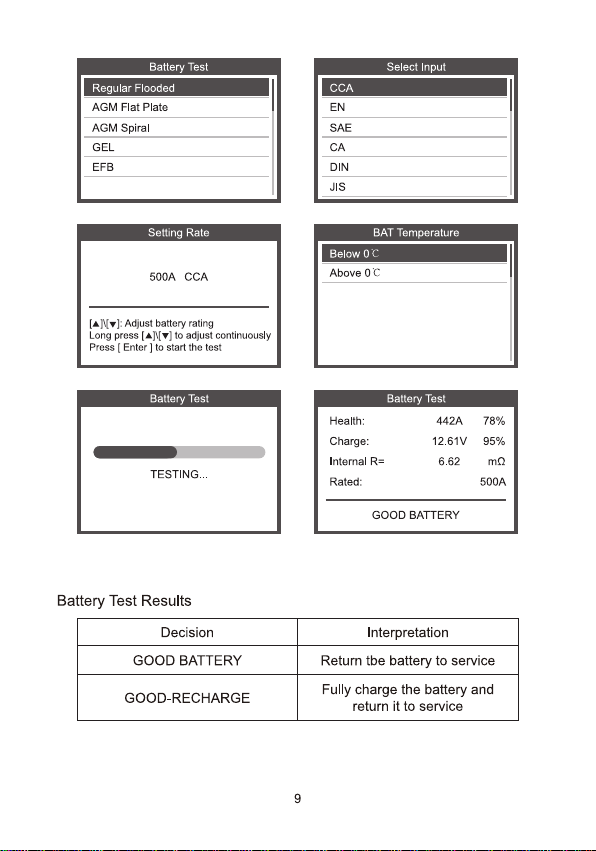
Battery Test Results
Decision
Interpretation
GOOD BATTERY
Return tbe battery to service
GOOD-RECHARGE
Fully charge the battery and
return it to service
9
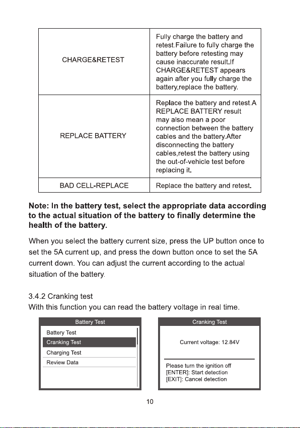
CHARGE&RETEST
Fully charge the battery and
retest.Failure to fully charge the
battery before retesting may
cause inaccurate result.If
CHARGE&RETEST appears
again after you fully charge the
battery,replace the battery.
REPLACE BATTERY
Replace the battery and retest.A
REPLACE BATTERY result
may also mean a poor
connection between the battery
cables and the battery.After
disconnecting the battery
cables,retest the battery using
the out-of-vehicle test before
replacing it.
BAD CELL-REPLACE
Replace the battery and retest.
Note: In the battery test, select the appropriate data according
to the actual situation of the battery to finally determine the
health of the battery.
When you select the battery current size, press the UP button once to
set the 5A current up, and press the down button once to set the 5A
current down. You can adjust the current according to the actual
situation of the battery.
3.4.2 Cranking test
With this function you can read the battery voltage in real time.
Battery Test
Battery Test
Cranking Test
Charging Test
Review Data
Cranking Test
Current voltage:12.84V
Please turn the ignition off
[ENTER]: Start detection
[EXIT]: Cancel detection
10
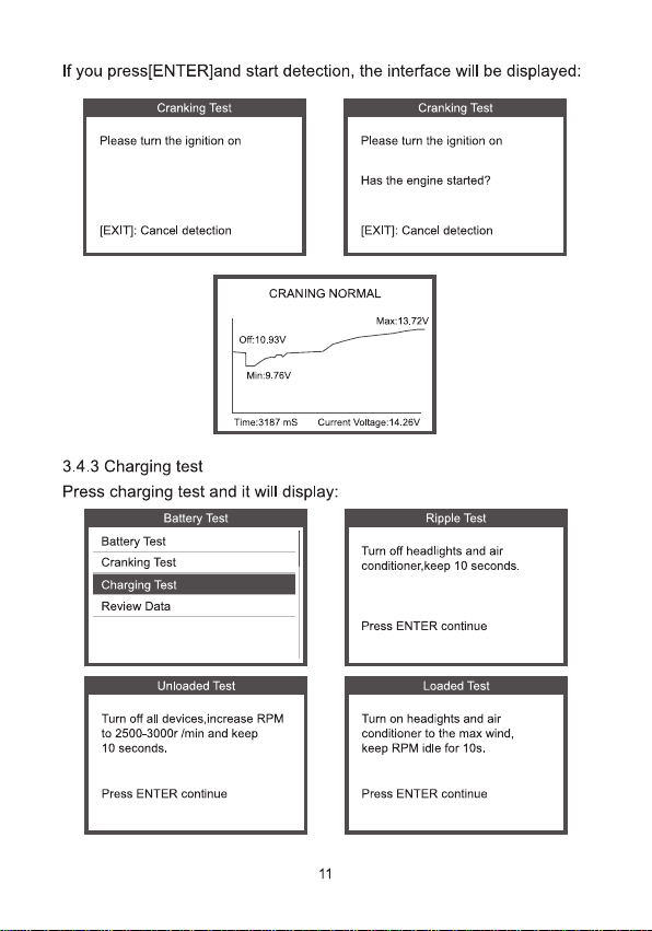
If you press[ENTER]and start detection, the interface will be displayed:
Cranking Test
Please turn the ignition on
[EXIT]: Cancel detection
Cranking Test
Please turn the ignition on
Has the engine started?
[EXIT]: Cancel detection
CRANING NORMAL
Of:10.93V
Max:13.72V
Min:9.76V
Time:3187 ms
Curent Voltage:14.26V
3.4.3 Charging test
Press charging test and it will display:
Battery Test
Battery Test
Cranking Test
Charging Test
Review Data
Ripple Test
Tur off headlights and air
conditioner.keep 10 seconds.
Press ENTER continue
Unloaded Test
Turn off all devices,increase RPM
to 2500-3000r /min and keep
10 seconds.
Press ENTER continue
Loaded Test
Tur on headights and air
conditioner to the max wind,
keep RPM idle for 10s.
Press ENTER continue
11
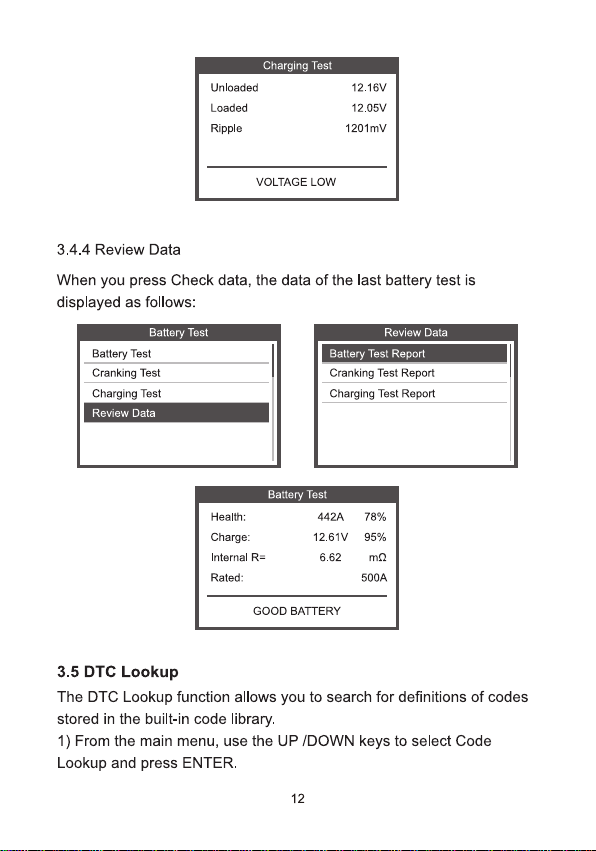
Charging Test
Unloaded
Loaded
Ripple
12.16V
12.05V
1201mv
VOLTAGE LOW
3.4.4 Review Data
When you press Check data, the data of the last battery test is
displayed as follows:
Battery Test
Review Data
Battery Test
Battery Test Report
Cranking Test
Cranking Test Report
Charging Test
Charging Test Report
Review Data
Battery Test
Health:
Charge
Internal R=
Rated:
442A
78%
12.61V
95%
6.62
m2
500A
GOOD BATTERY
3.5 DTC Lookup
The DTC Lookup function allows you to search for definitions of codes
stored in the built-in code library.
1) From the main menu, use the UP /DOWN keys to select Code
Lookup and press ENTER.
12
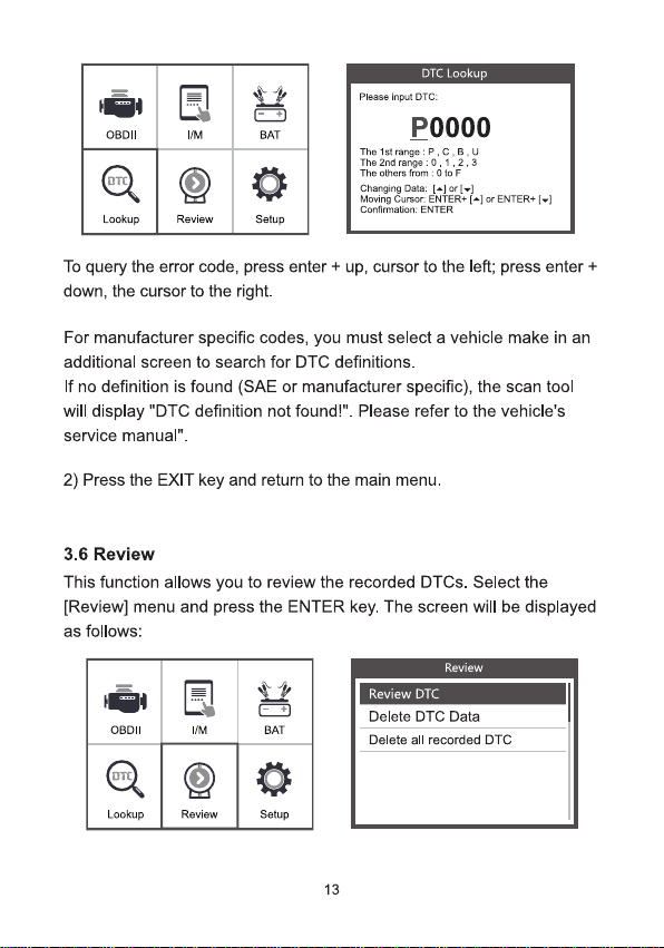
OBDII
I/M
+
BAT
(oT)
Lookup
Review
Setup
DTC Lookup
Pkase input DTC:
P0000
The 1st range:P,C;B,u
The 2nd range:0.1.2.3
The others from:OtoF
Changing Data:[÷lor(-)
Moving Cursor ENIER+[-]ar ENTER+[-1
Confirmation: ENTER
To query the error code,press enter + up, cursor to the left; press enter +
down, the cursor to the right.
For manufacturer specific codes, you must select a vehicle make in an
additional screen to search for DTC definitions.
If no definition is found (SAE or manufacturer specific), the scan tool
will display "DTC definition not found!". Please refer to the vehicle's
service manual".
2) Press the EXIT key and return to the main menu.
3.6 Review
This function allows you to review the recorded DTCs.Select the
[Review] menu and press the ENTER key. The screen will be displayed
as follows:
Review
OBDII
IM
+
BAT
(oπi)
Lookup
Review
Setup
Review DTC
Delete DTC Data
Delete al recorded DTC
13
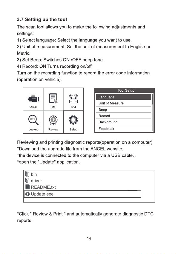
3.7 Setting up the tool
The scan tool allows you to make the following adjustments and
settings:
1) Select language: Select the language you want to use.
2) Unit of measurement: Set the unit of measurement to English or
Metric.
3)Set Beep: Switches ON /OFF beep tone.
4) Record: ON Turns recording on/off.
Turn on the recording function to record the error code information
(operation on vehicle).
Tool Setup
Language
OBDII
I/M
BAT
aTo)
Lookup
Review
Setup
Unit of Measure
Beep
Record
Background
Feedback
Reviewing and printing diagnostic reports(operation on a computer)
*Download the upgrade file from the ANCEL website.
*the device is connected to the computer via a USB cable..
*open the "Update" application.
题bin
driver
目README.txt
Update.exe
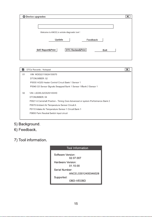
Click"Review & Print"and automatically generate diagnostic DTC
reports.
14
Device upgrades
×
Welsama to ANCELs vehidle dlagnoste tool!
Update
Feedback
BAT Report8Print
DTC Beyiew&Print
Exit
目DTCs Recards -Nctepad
×
01 1
VIN:WDD2211582A155070
DTCNUMBER:02
P0030 HO2S Heater Contrdl Circuit Bank 1 Sensor 1
P004002 Sensar Signals Swapped Bank 1 Sensor 1/Bank 2 Senscr 1
02 VIN:LSGWL520×2S140440
DTCNUMBER:04
P0021 A Camshaft Fesiicn -Timing Over-Advanced or sysem Performance Bank.2
P0070 Artient Air Temperature Sensor Circuit A
P0110 Intake Air Temperature Sensor 1 Circuit Bank 1
POBSO Park Neutral swich Input cicult
5) Background.
6)Feedback.
7) Tool information.
Tool Information
Software Version:
02.07.007
Hardware Version:
01.10.00
Serial Number:
ANCEL53012400346028
Supported:
OBD-IUEOBD
15
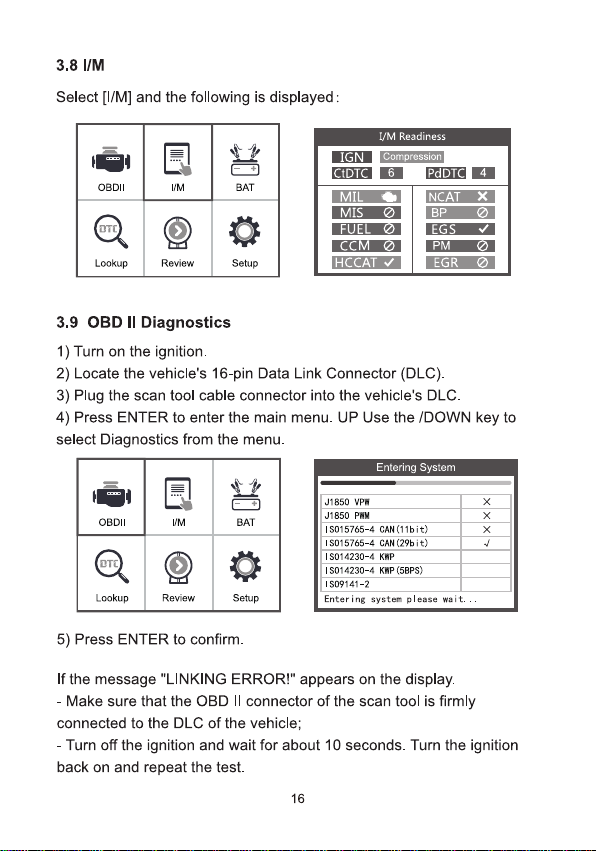
3.8 I/M
Select [[/M] and the following is displayed:
OBDII
三|
IM
BAT
oTd)
Lookup
Review
Setup
IGN
tDTC
I/M Readiness
compression
6
4
MIL
MIS
FUEL
CCM
HCCATI
NCATX
BP
EGS
PM
EGR
3.9 OBD l Diagnostics
1) Turn on the ignition.
2) Locate the vehicle's 16-pin Data Link Connector (DLC).
3)Plug the scan tool cable connector into the vehidle's DLC.
4) Press ENTER to enter the main menu.UP Use the /DOWN key to
select Diagnostics from the menu.
Entering System
OBDII
IM
BAT
(org)
Lookup
Review
Setup
J1850 VPW
×
J1850 PWM
×
IS015765-4 CAN(11bit)
×
I5015765-4 CAH(29bit)
√
I5014230-4 KMP
I5014230-4 KWP(5BPS)
1S09141-2
Entering system please wait..
5) Press ENTER to confirm.
If the message "LINKING ERROR!" appears on the display.
-Make sure that the OBD lI connector of the scan tool is firmly
connected to the DLC of the vehicle;
-Turn off the ignition and wait for about 10 seconds. Turn the ignition
back on and repeat the test.
16
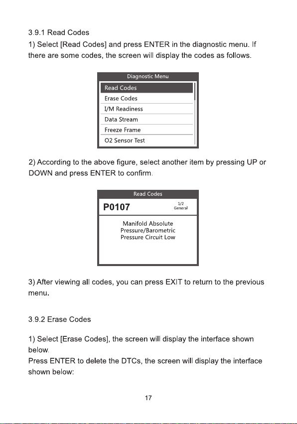
3.9.1 Read Codes
1) Select [Read Codes] and press ENTER in the diagnostic menu.If
there are some codes, the screen will display the codes as follows.
Diagnostic Menu
Read Codes
Erase Codes
I/M Readiness
Data Stream
Freeze Frame
O2 Sensor Test
2) According to the above figure, select another item by pressing UP or
DOWN and press ENTER to confirm.
Read Codes
P0107
1/2,
General
Manifold Absolute
Pressure/Barometric
Pressure Circuit Low
3)After viewing all codes, you can press EXIT to return to the previous
menu.
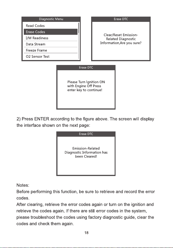
3.9.2 Erase Codes
1)Select [Erase Codes], the screen will display the interface shown
below.
Press ENTER to delete the DTCs, the screen will display the interface
shown below:
17
Diagnostic Menu
Read Codes
Erase Codes
I/M Readiness
Data Stream
Freeze Frame
O2 Sensor Test
Erase DTC
Clear/Reset Emission-
Related Diagnostic
Information,Are you sure?
Erase DTC
Please Turn lgnition ON
with Engine Off Press
enter key to continue!
2) Press ENTER according to the figure above. The screen will display
the interface shown on the next page:
Erase DTC
Emission-Related
Diagnostic Information has
been Cleared!
Notes:
Before performing this function, be sure to retrieve and record the error
codes.
After clearing, retrieve the error codes again or turn on the ignition and
retrieve the codes again. If there are still error codes in the system,
please troubleshoot the codes using factory diagnostic guide, clear the
codes and check them again.
18
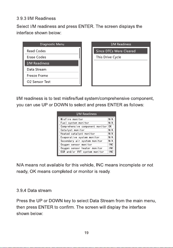
3.9.3 l/M Readiness
Select /M readiness and press ENTER. The screen displays the
interface shown below:
Diagnostic Menu
Read Codes
Erase Codes
1/M Readiness
Data Stream
Freeze Frame
O2 Sensor Test
1/M Readiness
Since DTCs Were Cleared
This Drive Cycle
//M readiness is to test misfire/fuel system/comprehensive component,
you can use UP or DOWN to select and press ENTER as follows:
I/M Readiness
Wisfire monitar
N/A
Fuel system monitor
W/A
Comprehensive component monitor
OK
Catalyst monitor
N/A
Heated cata lyst monitor
N/A
Evaporat ive system menitor
N/A
Secondary air system monitor
N/A
Oxygen sensor menitor
ING
Oxygen sensor heater manitor
INC
EGR and/ar WVT syetem monitar
ING
N/A means not available for this vehicle, INC means incomplete or not
ready, OK means completed or monitor is ready.
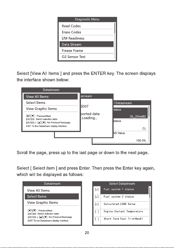
3.9.4 Data stream
Press the UP or DOWN key to select Data Stream from the main menu,
then press ENTER to confirm. The screen will display the interface
shown below:
19
Diagnostic Menu
Read Codes
Erase Codes
I/M Readiness
Data Stream
Freeze Frame
O2 Sensor Test
Select [View All ltems ]and press the ENTER key. The screen displays
the interface shown below:
Datastream
View All Items
Select Items
View Graphic Items
[A]\W]:PreaicuslNest
ENTER:Swich seloction stats
ENTER+[A]\E
]:te PreviustNestpege
EXIT: To the Daastoan dsplay roafaos
astream
D07
borted data
.Loading…
Ⅱl Datastream
status
OL_DriveB2
status
CL
AD Value
100.0%
Scroll the page, press up to the last page or down to the next page.
Select [ Select item ]and press Enter. Then press the Enter key again,
which will be displayed as follows:
Datastream
View All Items
Select Items
View Graphic Items
[A]\Y]:PrevousilNest
ENTER:Swich selkcton stste
ENTER+[u
:the Previous; Nestpage
EXIT To the Dstestrgam dsplky intertsce
[.1
[J]
Select Datastream
Fuel system 1 status
Fuel system 2 status
[J]
Calculated LOAD Value
[1
Engine Coolant Temperature
[]
Short Term Fuel Trim-tank1
20
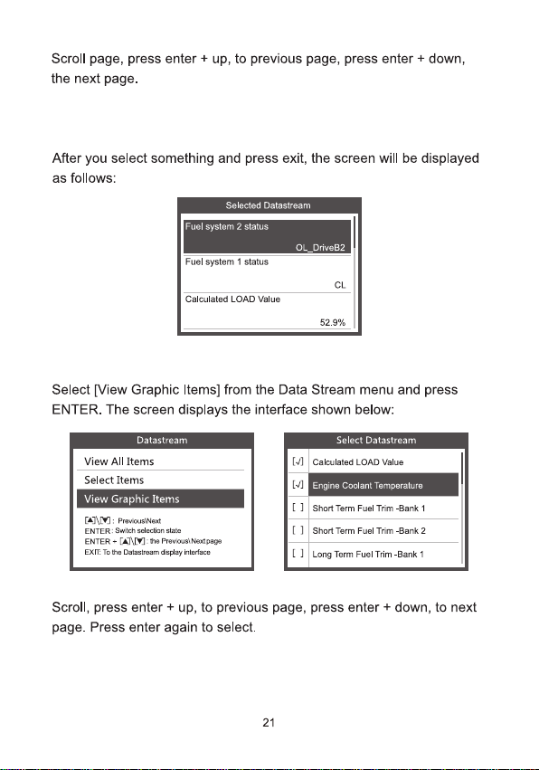
Scroll page, press enter + up, to previous page, press enter + down,
the next page.
After you select something and press exit, the screen will be displayed
as follows:
Selecled Datastream
Fuel system 2 status
OL_DriveB2
Fuel system 1 status
CL
Calculated LOAD value
52.9%
Select [View Graphic Items] from the Data Stream menu and press
ENTER. The screen displays the interface shown below:
Datastream
View All Items
Select Items
View Graphic Items
[A]\V]:PreviousiNest
ENTER:Switch seleclion stale
ENTER+[
]:ths PrwvoustNestpage
EAT. Te the Dstlastream dspday interlace
Select Datastream
[J]
Calculated LOAD Value
[J]
Engine Coolant Temperature
[ 1
Short Term Fuel Trim -Bank 1
[]
Short Term Fuel Trim -pank 2
[]
Long Term Fuel Trm -Bank 1
Scroll, press enter + up, to previous page, press enter + down, to next
page. Press enter again to select.
21
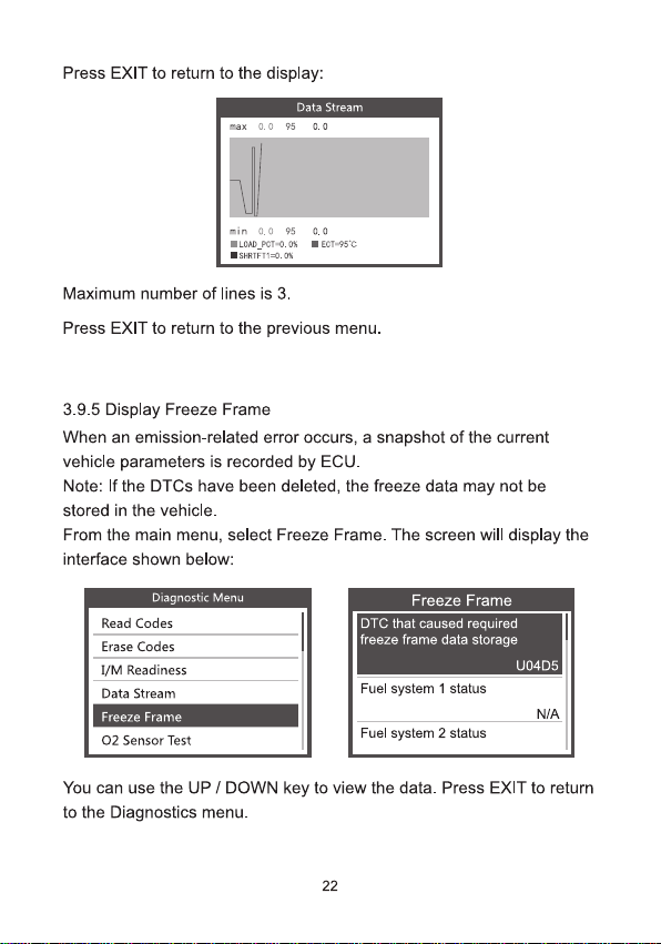
Press EXIT to return to the display:
Data Stream
max 0.0 95 0.0
min 0.0 95 0.0
■LOAD_PCT=0.0 ■ECT=95℃
■SHHTFT1=0.0%
Maximum number of lines is 3.
Press EXIT to return to the previous menu.
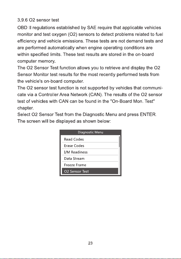
3.9.5 Display Freeze Frame
When an emission-related error occurs,a snapshot of the current
vehicle parameters is recorded by ECU.
Note: If the DTCs have been deleted, the freeze data may not be
stored in the vehicle.
From the main menu, select Freeze Frame. The screen will display the
interface shown below:
Diagnostic Menu
Read Codes
Erase Codes
I/M Readiness
Data Stream
Freeze Frame
O2 Sensor Test
Freeze Frame
DTC that caused required
freeze frame data storage
U04D5
Fuel system 1 status
N/A
Fuel system 2 status
You can use the UP/DOWN key to view the data.Press EXIT to return
to the Diagnostics menu.
22
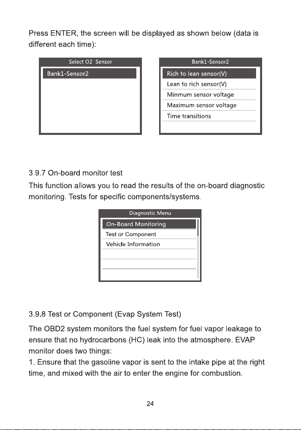
3.9.6 〇2 sensor test
OBD lI regulations established by SAE require that applicable vehicles
monitor and test oxygen (O2) sensors to detect problems related to fuel
efficiency and vehicle emissions. These tests are not demand tests and
are performed automatically when engine operating conditions are
within specified limits. These test results are stored in the on-board
computer memory
The O2 Sensor Test function allows you to retrieve and display the O2
Sensor Monitor test results for the most recently performed tests from
the vehicle's on-board computer.
The O2 sensor test function is not supported by vehicles that communi-
cate via a Controller Area Network (CAN). The results of the O2 sensor
test of vehicles with CAN can be found in the "On-Board Mon. Test"
chapter.
Select O2 Sensor Test from the Diagnostic Menu and press ENTER.
The screen will be displayed as shown below:
Diagnostic Menu
Read Codes
Erase Codes
I/M Readiness
Data Stream
Freeze Frame
O2 Sensor Test
23
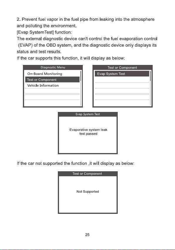
Press ENTER, the screen will be displayed as shown below(data is
different each time):
Select O2 Sensor
Bank1-Sensor2
Bank1-Sensor2
Rich to lean sensor(V)
Lean to rich sensor(V)
Minmum sensor voltage
Maximum sensor voltage
Time transitions
3.9.7 On-board monitor test
This function allows you to read the results of the on-board diagnostic
monitoring. Tests for specific components/systems.
Dipanostic Menu
On-Board Monitoring
Test or Component
Vehicle Information
3.9.8 Test or Component (Evap System Test)
The OBD2 system monitors the fuel system for fuel vapor leakage to
ensure that no hydrocarbons (HC) leak into the atmosphere. EVAP
monitor does two things:
1. Ensure that the gasoline vapor is sent to the intake pipe at the right
time, and mixed with the air to enter the engine for combustion.
24
2. Prevent fuel vapor in the fuel pipe from leaking into the atmosphere
and polluting the environment.
[Evap SystemTest] function:
The external diagnostic device can't control the fuel evaporation control
(EVAP) of the OBD system, and the diagnostic device only displays its
status and test results.
If the car supports this function, it will display as below:
Diagnostic Menu
On-Board Monitoring
Test or Component
Vehicle Information
Test or Component
Evap System Test
Evap System Test
Evaporative system leak
test passed
If the car not supported the function ,it will display as below:
Test or Component
Not Supported
25
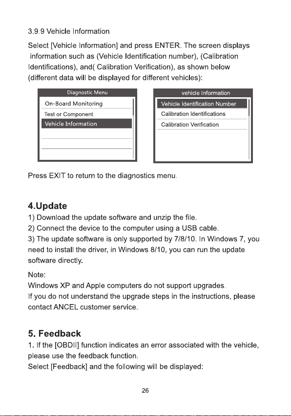
3.9.9 Vehicle Information
Select [Vehicle Information] and press ENTER. The screen displays
information such as (Vehicle Identification number),(Calibration
ldentifications),and( Calibration Verification), as shown below
(different data will be displayed for different vehicles):
Diagnostic Menu
On-Board Monitoring
Test or Component
Vehicle Information
vehicle Information
Vehicle ldentification Number
Calibration ldentfications
Calibration Verification
Press EXIT to return to the diagnostics menu.
4.Update
1) Download the update software and unzip the file.
2) Connect the device to the computer using a USB cable.
3) The update software is only supported by 7/8/10.In Windows 7, you
need to install the driver, in Windows 8/10,you can run the update
software directly.
Note:
Windows XP and Apple computers do not support upgrades.
If you do not understand the upgrade steps in the instructions, please
contact ANCEL customer service.
5. Feedback
1. If the [OBDI] function indicates an error associated with the vehicle,
please use the feedback function.
Select [Feedback] and the following will be displayed:
26
Togl Setup
Language
OBDII
IM
BAT
(oT)
Lookup
Review
Setup
Unit of Measure
Beep
Record
Background
Feedback
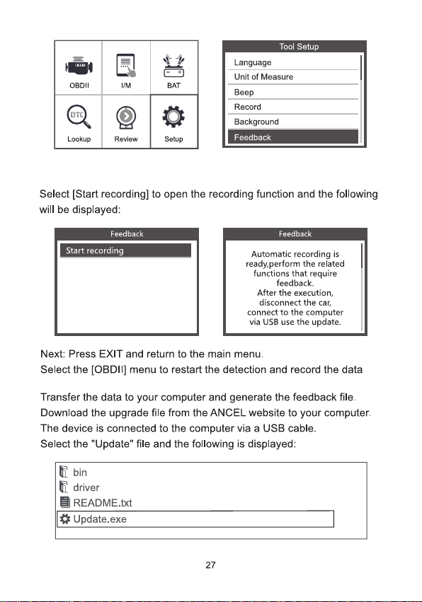
Select [Start recording] to open the recording function and the following
will be displayed:
Feedback
Start recording
Feedback
Automatic recording is
ready.perform the related
functions that require
feedback.
After the execution,
disconnect the car,
connect to the computer
via USB use the update.
Next: Press EXIT and return to the main menu.
Select the [OBDlI] menu to restart the detection and record the data
Transfer the data to your computer and generate the feedback file.
Download the upgrade file from the ANCEL website to your computer.
The device is connected to the computer via a USB cable.
Select the "Update" file and the following is displayed:
题bin
driver
目README.txt
Update.exe
27
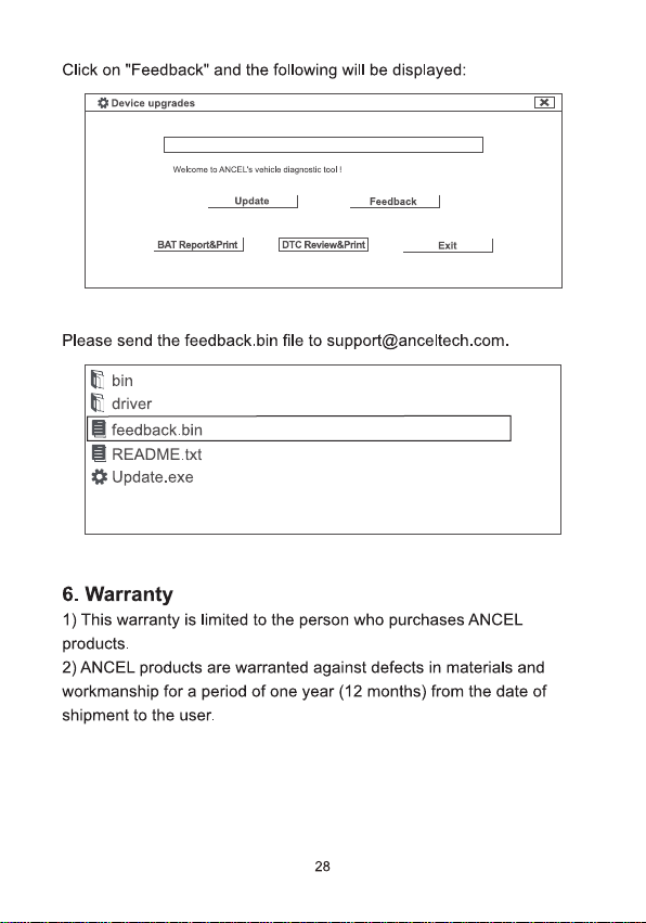
Click on "Feedback" and the following will be displayed:
卷Device upgrades
×
Welcome to ANCEL's vehick diagnastie ted!
Update
Feedback
BAT Report&Print |
DTC Review&Print
Exit
Please send the feedback.bin file to support@anceltech.com.
晶bin
driver
目feedback.bin
目README.txt
Update.exe
6.Warranty
1) This warranty is limited to the person who purchases ANCEL
products.
2)ANCEL products are warranted against defects in materials and
workmanship for a period of one year (12 months) from the date of
shipment to the user.
28

OBDSPACE TECHNOLOGY CO.,LTD
Address: D03, Block A, No.973 Minzhi Ave, Longhua
District, Shenzhen, Guangdong, China
support@anceltech.com www.anceltech.com
CEFC皆 区尿
LETRI
9FACILE
8hparoe hos Mawr apant dn trho
MADE IN CHINA
