Loading ...
Loading ...
Loading ...

ENGLISH
10
Specifications
Capacity of cut
50° miter left and 60° miter right
49º bevel left and right
0° miter
Max. Height 4.4" (112 mm) Resulting Width 10.9" (278 mm)
Max. Width 12.2" (310 mm) Resulting Height 3.5" (90mm)
45° miter
Max. Height 4.4" (112 mm) Resulting Width 7.7" (197 mm)
Max. Width 8.6" (219 mm) Resulting Height 3.5" (90 mm)
45° bevel ‑ Left
Max. Height 2.4" (60 mm) Resulting Width 10.9" (278 mm)
Max. Width 12.2" (310 mm) Resulting Height 2.1" (54 mm)
45º bevel ‑ Right
Max. Height 2.0" (50 mm) Resulting Width 11.65" (296 mm)
Max. Width 12.2" (310 mm) Resulting Height 1.6" (40 mm)
Your saw is capable of cutting baseboard moldings 0.75" (19mm) thick by 6.5" (165mm) tall
on a 45° right or leftmiter.
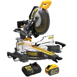
Unpacking Your Saw
Check the contents of your miter saw carton to make sure that you have received all parts. In
addition to this instruction manual, the carton should contain:
1 DCS781 miter saw
1 Stabilizer bar
1 Vacuum adapter
1
DEWALT 12" (305 mm) diameter saw blade
2 Base extensions
1 Material clamp
1 Charger (Kit only)
1 Battery (Kit only)
In bag:
1 Dust bag
1 Blade wrench
1 Instruction manual
NOTE: Your miter saw is fully and accurately adjusted at the factory at the time of
manufacture. If readjustment due to shipping and handling or any other reason is required,
follow the steps below to adjust yoursaw.
Once made, these adjustments should remain accurate. Take a little time now to follow these
directions carefully to maintain the accuracy of which your saw iscapable.
Wall Mounting
Some DEWALT chargers are designed to be wall mountable or to sit upright on a table or
work surface. If wall mounting, locate the charger within reach of an electrical outlet, and
away from a corner or other obstructions which may impede air flow. Use the back of the
charger as a template for the location of the mounting screws on the wall. Mount the charger
securely using drywall screws (purchased separately) at least 1” (25.4mm) long, with a screw
head diameter of 0.28–0.35” (7–9mm), screwed into wood to an optimal depth leaving
approximately 7/32” (5.5 mm) of the screw exposed. Align the slots on the back of the charger
with the exposed screws and fully engage them in theslots.
ASSEMBLY AND ADJUSTMENTS
WARNING: To reduce the risk of serious personal injury, turn tool off, and remove
the battery pack before transporting, making any adjustments, cleaning,
repairing, or removing/installing attachments or accessories. An accidental
start‑up can causeinjury.
2. The charger and battery pack may become warm to the touch while charging. This is a
normal condition, and does not indicate a problem. To facilitate the cooling of the battery
pack after use, avoid placing the charger or battery pack in a warm environment such as in
a metal shed or an uninsulatedtrailer.
3. If the battery pack does not charge properly:
a. Check operation of receptacle by plugging in a lamp or other appliance;
b. Check to see if receptacle is connected to a light switch which turns power off when
you turn out the lights;
c. If charging problems persist, take the tool, battery pack and charger to your local
servicecenter.
4. You may charge a partially used pack whenever you desire with no adverse effect on the
batterypack.
Charger Cleaning Instructions
WARNING:Shock hazard. Disconnectthe charger from the AC outlet before cleaning.
Dirt and grease may be removed from the exterior of the charger using a cloth or soft
non‑metallic brush. Do not use water or any cleaningsolutions.
• Do not use an extension cord unless it is absolutely necessary. Use of improper
extension cord could result in risk of fire, electric shock orelectrocution.
• When operating a charger outdoors, always provide a dry location and use an
extension cord suitable for outdoor use. Use of a cord suitable for outdoor use reduces the
risk of electricshock.
• An extension cord must have adequate wire size (AWG or American Wire Gauge) for
safety. The smaller the gauge number of the wire, the heavier the cord and thus the greater
its capacity. An undersized cord will cause a drop in line voltage resulting in loss of power and
overheating. The following table shows the correct size to use depending on total length of
all extension cords plugged together, and nameplate ampere rating. If in doubt, use the next
heaviergauge.
Minimum Gauge for Cord Sets
Volts
Total Length of Cord in Feet
(meters)
120V 25 (7.6) 50 (15.2) 100 (30.5) 150 (45.7)
Ampere Rating
American Wire Gauge
More Than Not More
Than
0 6 18 16 16 14
6 10 18 16 14 12
10 12 16 16 14 12
12 16 14 12 Not Recommended
• Do not place any object on top of the charger or place the charger on a soft surface
that might block the ventilation slots and result in excessive internal heat. Place the
charger in a position away from any heat source. The charger is ventilated through slots in the
top and the bottom of thehousing.
• Do not operate the charger with a damaged cord orplug. Have them
replacedimmediately.
• Do not operate the charger if it has received a sharp blow, been dropped or
otherwise damaged in any way. Take it to an authorized servicecenter.
• Do not disassemble the charger; take it to an authorized service center when service
or repair is required. Incorrect reassembly may result in a risk of electric shock, electrocution
orfire.
• The charger is designed to operate on standard 120V household electrical power. Do
not attempt to use it on any other voltage. This does not apply to the vehicularcharger.
• Foreign materials of a conductive nature, such as, but not limited to, grinding dust,
metal chips, steel wool, aluminum foil or any buildup of metallic particles should be
kept away from the charger cavities and ventilation slots.
• Always unplug the charger from the power supply when there is no battery pack in
thecavity.
Charging a Battery (Fig. C).
1. Plug the charger into an appropriate outlet.
2. Insert and fully seat battery pack. The red charging light(s) will continuously blink
whilecharging.
3. Charging is complete when the red charging light(s) remain(s) continuously ON. Battery
pack can be left in charger or removed. Some chargers require the battery pack release
button to be pressed forremoval.
WARNING: Only charge batteries in air temperature over 40°F (4.5° C) and below 104°F
(+40°C).
4. Charger will not charge a faulty battery pack, which may be indicated by the charging
light(s) staying OFF. Take charger and battery pack to an authorized service center if
light(s) stay(s)OFF.
NOTE: Refer to label near charging light(s) on charger for blinkpatterns. Older chargers
may have additional information and/or may not have a yellow indicatorlight.
NOTE: To remove the battery pack, some chargers require the battery pack release button
to bepressed.
Hot/Cold Pack Delay
When the charger detects a battery pack that is too hot or too cold, it automatically starts a
Hot/Cold Pack Delay, suspending charging until the battery pack has reached an appropriate
temperature. The charger then automatically switches to the pack charging mode. This feature
ensures maximum battery packlife.
A cold battery pack may charge at a slower rate than a warm batterypack.
The hot/cold pack delay will be indicated by the red light(s) continuing to blink but with the
yellow light continuously ON. Once the battery pack has reached an appropriate temperature,
the yellow light will turn OFF and the charger will resume the chargingprocedure.
DCB118 and DCB1112 Chargers
The DCB118 and DCB1112 chargers are equipped with an internal fan designed to cool the
battery pack. The fan will turn on automatically when the battery pack needs to becooled.
Never operate the charger if the fan does not operate properly or if ventilation slots are
blocked. Do not permit foreign objects to enter the interior of thecharger.
Electronic Protection System
Li‑Ion tools are designed with an Electronic Protection System that will protect the battery
pack against overloading, overheating or deep discharge. The tool will automatically turn off
and the battery pack will need to berecharged.
Important Charging Notes
1. Longest life and best performance can be obtained if the battery pack is charged when the
air temperature is between 65°F – 75°F (18° C– 24°C). DO NOT charge when the battery
pack is below +40°F (+4.5°C), or above +104°F (+40°C). This is important and will
prevent serious damage to the batterypack.
Loading ...
Loading ...
Loading ...