Loading ...
Loading ...
Loading ...
20 31-5000553 Rev. 1
ENGLISH
Dip Switch Setting
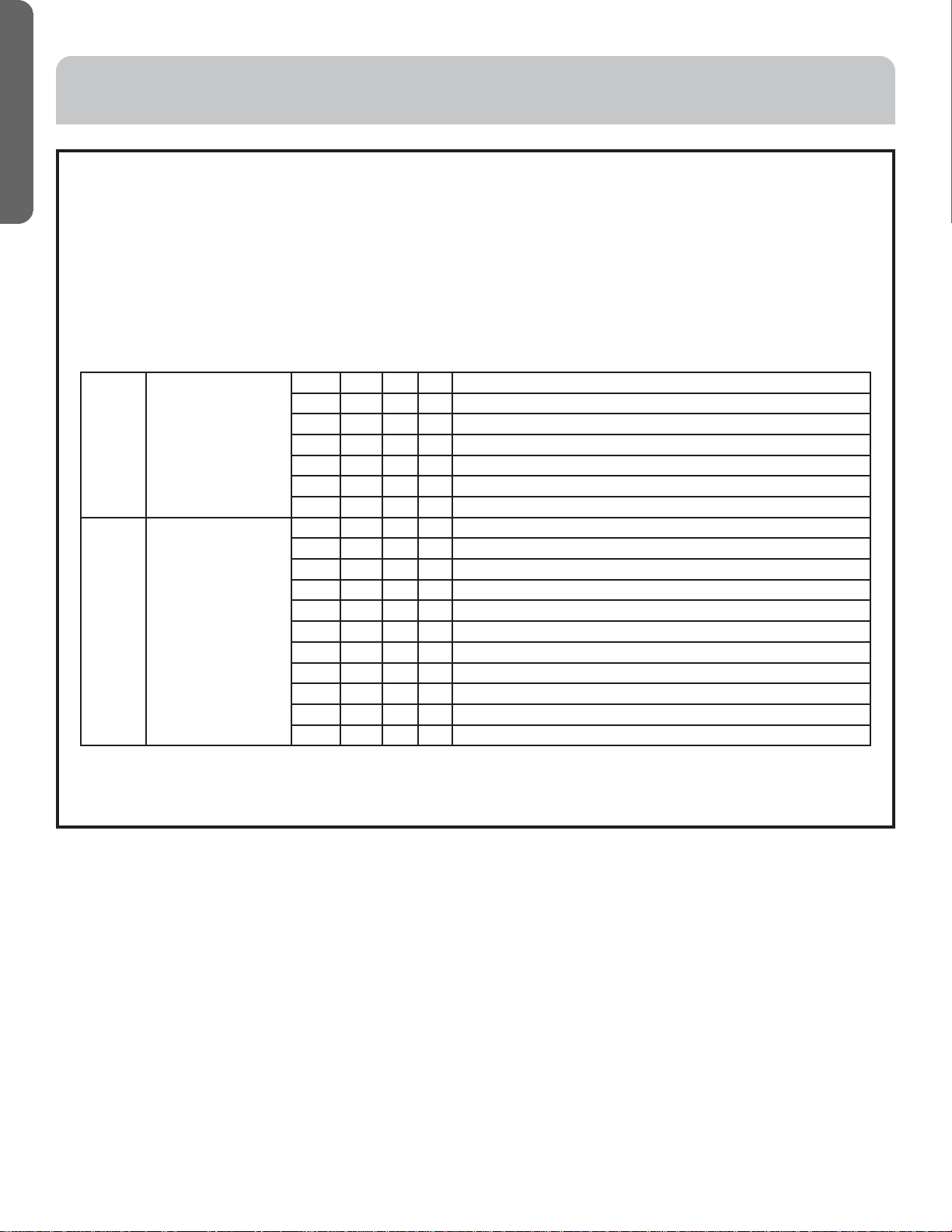
• The dip switch is set to the "On" position if “1” is indicated in the table. The dip switch is set to the "Off" position if "0" is
indicated in the table.
• Dip switches set in the factory to on are marked with red.
Definition principles of code switches:
(A) Definition of SW01:
• SW01_1-4 is used to set indoor address when grouping multiple indoor units connected to single wired controller
YRE16B or YR-E17.
• SW01_5-8 set capacity of the indoor unit (factory set). Must only set when replacing board.
Note : A wired controller can be connected to sixteen ultra thin air-duct indoor units maximum.
ELECTRICAL WIRING
SW01_1
SW01_2
SW01_3
SW01_4
Address of wire
controlled indoor unit
(group address)
[1] [2] [3] [4] Address of wire controlled indoor unit (group address)
0 0 0 0 0# (wire controlled main unit) (default)
0 0 0 1 1# (wire controlled sub unit)
0 0 1 1 2# (wire controlled sub unit)
0 0 1 1 3# (wire controlled sub unit)
••• ••• ••• ••• •••• •••
1 1 1 1 15# (wire controlled sub unit)
SW01_5
SW01_6
SW01_7
SW01_8
Capability of indoor unit [5] [6] [7] [8] Capability of indoor unit
0 0 0 1 7000BTU
0 0 1 0 9000BTU
0 0 1 1 12000BTU
0 1 1 0 18000BTU
0 1 1 1 24000BTU
1 0 1 0 36000BTU
1 0 1 1 48000BTU
1 1 0 0 54000BTU
1 1 0 1 72000BTU
1 1 1 0 96000BTU
Loading ...
Loading ...
Loading ...