
Loading ...
Loading ...
Loading ...
27
I. Operation Notes
The appliance utilizes a pump-down solenoid valve in the icemaker and a control
low-pressure switch in the remote condensing unit to control operation of the magnetic
contactor in the remote condensing unit. This eliminates the need for an electrical
connection between the icemaker and remote condensing unit.
Control Low-Pressure Switch Settings:
Cut-Out: 9 PSIG. Differential: 20 PSIG. Cut-In: 29 PSIG.
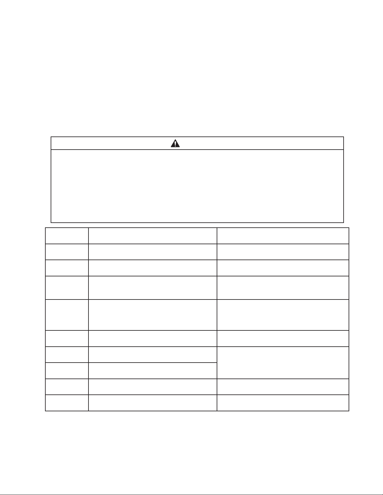
J. Alarm Safeties
Should an alarm occur, follow the instructions in the table below to address the alarm.
If an alarm continues to occur, contact an authorized service agent.
WARNING
• Only qualied service technicians should service the appliance.
• To reduce the risk of electric shock, do not touch the icemaker power switch or
control switch with damp hands.
• Before Servicing: Move the icemaker's power switch to the "OFF" position. Turn
off the power supply. Place the disconnect (if applicable) in the off position.
Lockout/Tagout to prevent the power supply from being turned back on
inadvertently.
No. of Beeps
(every 5 sec.)
Type of Alarm Reset Options
1 Low Water Safety
UFS open>90 sec. after WV energized.
Automatic reset once water supply is restored
and UFS closes.
2 Control Switch
In "DRAIN" position longer than 15 min.
Automatic reset once the control switch is
moved to the "ICE" position.
3 High-Pressure Switch
First and second activation in 1 hr.
Automatic reset once pressure drops below
the high pressure threshold and the high
pressure switch closes.
4 High-Pressure Switch
Third activation in 1 hr.
Call for service. To avoid possible catastrophic
failure, it is recommended to leave the
icemaker off until this alarm is resolved.
Manual reset. Turn power off and on again.
5 Freeze Timer
WV off > 30 min. since last WV activation.
Manual reset. Turn power off and on again.
6 Low Voltage
92VAC±5% or less
"POWER OK" LED turns off if voltage
protection operates.
The control voltage safeties automatically
reset when voltage is corrected.
7 High Voltage
147VAC±5% or more
8 Gear Motor
CCR contacts fail to close.
Manual reset. Turn power off and on again.
9 Infrared Sensor (CB S1 dip switch 7 on)
MBC engaged.
Manual reset. Turn power off and on again.
Legend: CB–control board; CCR–compressor control relay; FMR–fan motor-remote;
MBC–mechanical bin control; UFS–upper oat switch; WV–inlet water valve
Loading ...
Loading ...
Loading ...