Loading ...
Loading ...
Loading ...
THERMOSTAT
[]
FAN COIL
'CONTROL'
_R
W3
E
AIR COND.
A94058
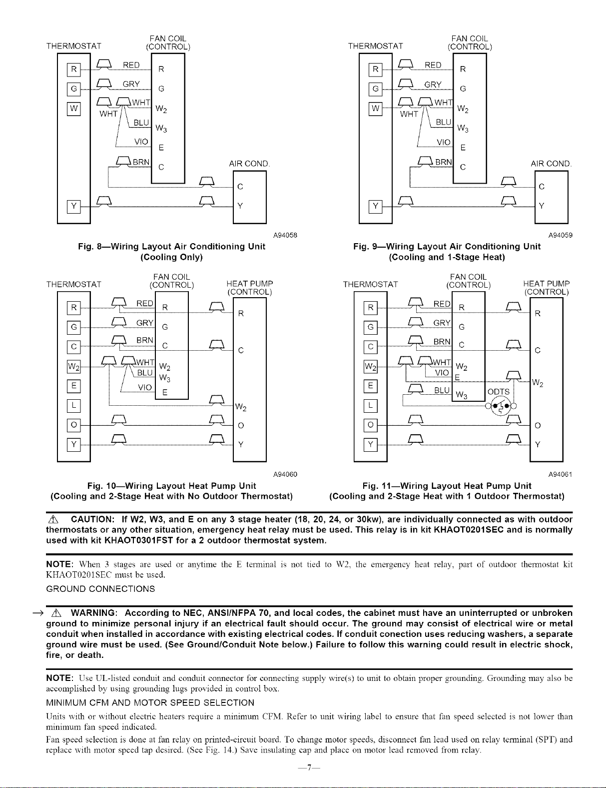
Fig, 8--Wiring Layout Air Conditioning Unit
(Cooling Only)
THERMOSTAT
[]-
[]
[]
FAN COIL
(CONTROL)
_G
W3
E___
HEAT PUMP
(CONTROL
R
C
W2
C3_o
z;_=¥
A94060
Fig, 10--Wiring Layout Heat Pump Unit
(Cooling and 2-Stage Heat with No Outdoor Thermostat)
THERMOSTAT FAN COIL
'CONTROL'
_zZL__ G
W3
E
AIR COND.
A94059
Fig. g--wiring Layout Air Conditioning Unit
(Cooling and l-Stage Neat)
THERMOSTAT
[]
[]
[Z]---
FAN COIL
(CONTROL)
R
_G
W30DTS
4q_
HEAT PUMP
CONTROL
R
C
W2
O
Y
A94061
Fig. 11--Wiring Layout Heat Pump Unit
(Cooling and 2-Stage Heat with 1 Outdoor Thermostat)
z_ CAUTION: If W2, W3, and E on any 3 stage heater (18, 20, 24, or 30kw), are individually connected as with outdoor
thermostats or any other situation, emergency heat relay must be used. This relay is in kit KHAOT0201SEC and is normally
used with kit KHAOT0301FST for a 2 outdoor thermostat system.
NOTE: When 3 stages are used or anytime the E terminal is not tied to W2, the emergency heat relay, part of outdoor themlostat kit
KHAOT0201SEC must be used.
GROUND CONNECTIONS
--> z_ WARNING: According to NEC, ANSI/NFPA 70, and local codes, the cabinet must have an uninterrupted or unbroken
ground to minimize personal injury if an electrical fault should occur. The ground may consist of electrical wire or metal
conduit when installed in accordance with existing electrical codes. If conduit conection uses reducing washers, a separate
ground wire must be used. (See Ground/Conduit Note below.) Failure to follow this warning could result in electric shock,
fire, or death.
NOTE: Use UL-listed conduit and conduit connector for connecting supply wire(s) to unit to obtain proper grounding. Grounding may also be
accomplished by using grounding lugs provided in control box.
MINIMUM CFM AND MOTOR SPEED SELECTION
Units with 02"without electric heaters require a mininmm CFM. Refer to unit wiring label to ensure that fan speed selected is not lower than
mininmm fan speed indicated.
Fan speed selection is done at fan relay on printed-circuit board. To change motor speeds, disconnect _an lead used on relay terminal (SPT) and
replace with motor speed tap desired. (See Fig. 14.) Save insulating cap and place on motor lead removed from relay.
7
Loading ...
Loading ...
Loading ...