Loading ...
POWERENTRY--_
OPTIONS_
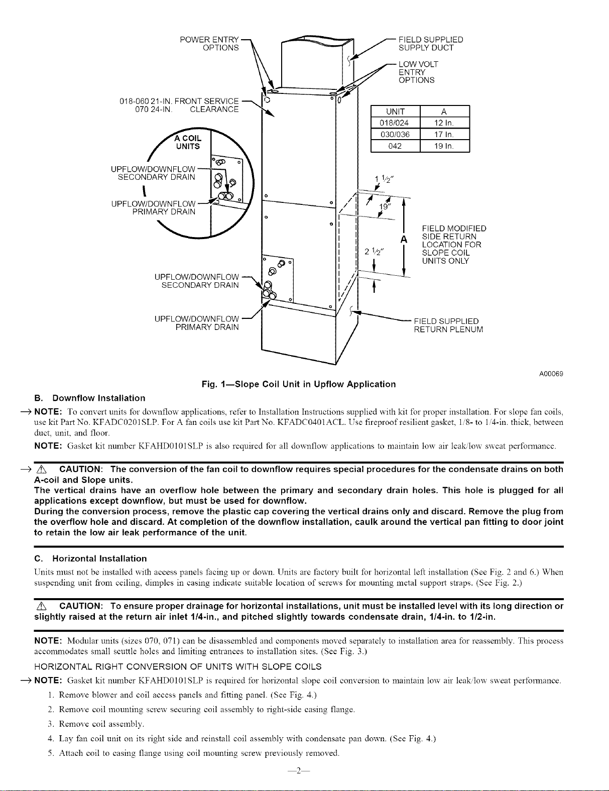
018-06021-1N.FRONTSERVICE
07024-1N. CLEARANCE
UPFLOW/_
2°w
PRIMA_
UPFLOW/DOWNFLOW
SECONDARY DRAIN II
UPFLOW/DOWN FLOW _/
PRIMARY DRAIN
_ IELDSUPPLIED
SUPPLYDUCT
OWVOL-
OPTIONS
UNIT A
0!8/024 12 In.
030/036 17 In.
042 !9 In.
FIELD MODIFIED
A SIDE RETURN
LOCATION FOR
SLOPE COIL
UNITS ONLY
FIELD SUPPLIED
RETURN PLENUM
A00069
Fig. l--Slope Coil Unit in Upflow Application
B. Downflow Installation
---->NOTE: To convert units for downflow applications, refer to Installation Instructions supplied with kit for proper installation. For slope fan coils,
use kit Part No. KFADC0201SLP. For A fan coils use kit Part No. KFADC0401ACL. Use fireproof resilient gasket, 1/8- to 1/4-in. thick, between
duct, unit, and floor.
NOTE: Gasket kit number KFAHD0101SLP is also required Ibr all downflow applications to maintain low air lea_low sweat performance.
--_ _CAUTION: The conversion of the fan coil to downflow requires special procedures for the condensate drains on both
A-coil and Slope units.
The vertical drains have an overflow hole between the primary and secondary drain holes. This hole is plugged for all
applications except downflow, but must be used for downflow.
During the conversion process, remove the plastic cap covering the vertical drains only and discard. Remove the plug from
the overflow hole and discard. At completion of the downflow installation, caulk around the vertical pan fitting to door joint
to retain the low air leak performance of the unit.
C. Horizontal Installation
Units must not be installed with access panels facing up or down. Units are factory built for horizontal left installation (See Fig. 2 and 6.) When
suspending unit from ceiling, dimples in casing indicate suitable location of screws for mounting metal support straps. (See Fig. 2.)
CAUTION: To ensure proper drainage for horizontal installations, unit must be installed level with its long direction or
slightly raised at the return air inlet 1/4-in., and pitched slightly towards condensate drain, 1/4-in. to 1/2-in.
NOTE: Modular units (sizes 070, 071) can be disassembled and components moved separately to installation area for reassembly. This process
accommodates small scuttle holes and limiting entrances to installation sites. (See Fig. 3.)
HORIZONTAL RIGHT CONVERSION OF UNITS WITH SLOPE COILS
NOTE: Gasket kit number KFAHD010ISLP is required 1"o1"horizontal slope coil conversion to maintain low air leak/low sweat pertbrmance.
i. Remove blower and coil access panels and fitting panel. (See Fig. 4.)
2. Remove coil mounting screw securing coil assembly to right-side casing flange.
3. Remove coil assembly.
4. Lay fan coil unit on its right side and reinstall coil assembly with condensate pan down. (See Fig. 4.)
5. Attach coil to casing flange using coil mounting screw previously removed.
2
Loading ...
Loading ...
Loading ...