Loading ...
Loading ...
Loading ...
UNIT t
2" MIN
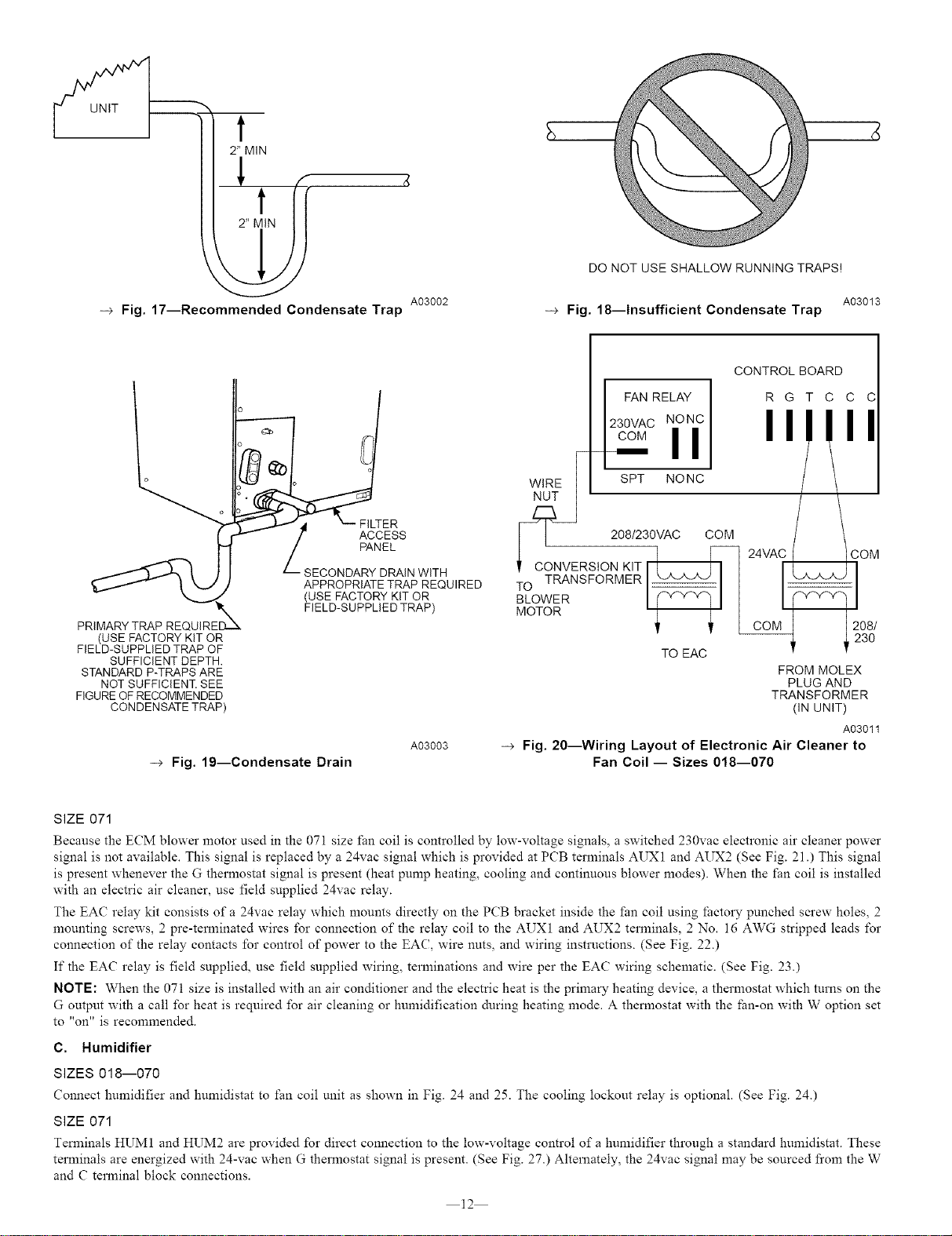
--_ Fig. 17--Recommended Condensate Trap A03002
DO NOT USE SHALLOW RUNNING TRAPS!
A03013
-_ Fig. 18--Insufficient Condensate Trap
PRIMARY TRAP REQUIRE_X_
(USE FACTORY KIT OR
FIELD-SUPPLIED TRAP OF
SUFFICIENT DEPTH.
STANDARD P-TRAPS ARE
NOT SUFFICIENT. SEE
FIGURE OF RECOMMENDED
CONDENSATE TRAP)
ACCESS
PANEL
SECONDARY DRAIN WiTH
APPROPRIATE TRAP REQUIRED
(USE FACTORY KIT OR
FIELD-SUPPLIED TRAP)
-_ Fig. 19--Condensate Drain
A03003
CONTROL BOARD
FAN RELAY R G T C C C
OVAC"If'
SPT NONC
ii 2o8,23OVACCOM
, CONVERSIONK,T,I OM
TO TRANSFORMER I
BLOWER I
MOTOR ; ;' [ 2?gg
TO EAC FROM MOLEX
PLUG AND
TRANSFORMER
(IN UNIT)
A03011
--_ Fig. 20--Wiring Layout of Electronic Air Cleaner to
Fan Coil -- Sizes 018--070
SIZE 071
Because the ECM blower motor used in the 071 size fan coil is controlled by low-voltage signals, a switched 230vac electronic air cleaner power
signal is not available. This signal is replaced by a 24vac signal which is provided at PCB terminals AUX 1 and AUX2 (See Fig. 21 .) This signal
is present whenever the G thermostat signal is present (heat pump heating, cooling and continuous blower modes). When the fan coil is installed
with an electric air cleaner, use field supplied 24vac relay.
The EAC relay kit consists of a 24vac relay which mounts directly on the PCB bracket inside the fan coil using facto W punched screw holes, 2
mounting screws, 2pre-temlinated wires for connection of the relay coil to the AUX1 and AUX2 terminals, 2 No. 16 AWG stripped leads for
connection of the relay contacts for control of power to the EAC, wire nuts, and wiring instructions. (See Fig. 22.)
If the EAC relay is field supplied, use field supplied wiring, terminations and wire per the EAC wiring schematic. (See Fig. 23.)
NOTE: When the 071 size is installed with an air conditioner and the electric heat is the primary heating device, a thermostat which turns on the
G output with a call for heat is required for air cleaning or humidification during heating mode. A themmstat with the _an-on with W option set
to "on" is recommended.
C. Humidifier
SIZES 018--070
Connect humidifier and humidistat to fan coil unit as shown in Fig. 24 and 25. The cooling lockout relay is optional. (See Fig. 24.)
SIZE 071
Terminals HUM1 and HUM2 are provided for direct connection to the low-voltage control of a humidifier through a standard humidistat. These
terminals are energized with 24-vac when G thermostat signal is present. (See Fig. 27.) Alternately, the 24vac signal may be sourced from the W
and C terminal block connections.
12
Loading ...
Loading ...
Loading ...